International Journal of Research (IJR)
e-ISSN: 2348-6848, p- ISSN: 2348-795X Volume 2, Issue 4, April 2015Available at http://internationaljournalofresearch.org
Abstract—
Due to the change in the nature and
environmental condition, the power which is being
generated from a renewable supply of energy
continually fluctuates. Similarly, by injection of
wind power into the electrical grid, some power
quality problems may rise because of the unsteady
nature of wind and relatively new types of
induction generators. For usingthe Doubly Fed
Induction Generators (DFIGs) as the primary
power supply in an isolated system, they are
supposed to be ready for regulating the voltage
and frequency of the system with Fault
Ride-Through (FRT) capability.
Voltage stability becoming an important criteria
to maintain the DFIG-based wind turbine
functioning during disturbances. This paper
proposes a new control strategy for riding through
the symmetrical faults for a DFIG operating in an
isolated power system which is done by a Static
Synchronous Compensator (STATCOM).When it is
integrated in a power system with conventional
synchronous generators, the Fault Ride-Through
capability of a DFIG is much improved by the
proposed control strategy while providing voltage
support and frequency balance to the system
throughout the fault duration. Thus, the stability in
the transient condition of the power system is
significantly improved. The developed system is
simulated and analyzed in MATLAB/Simulink
software.
KEYWORDS:
Wind Turbine; DFIG; Modeling; Voltage Sag;
STATCOM; Voltage Mitigation.
I. INTRODUCTION
As a result of global warming, the impact of
fossil fuel and non-renewable power generation on
the environment became a priority for scientist.
Due to these all issues, we are focussing on
non-conventional and clean energy such as wind, solar
and other such energies [1]. During the last
decades wind energy has received a huge boost
and determined as the most promising alternative
source of energy because of its availability and
cheapness in comparison with other resources.
One of the most vital renewable energy sources
are Wind Turbine Generators (WTGs), which are
very much used in the power islanded networks
and/or individual loads. DFIGs are fairly used in
various WTG types due to their back-to-back
partially rated power converter system and
variable speed operation with their relatively
simple control.
With the increase in wind turbines technology,
the demand for this non-conventional wind energy
has also increased drastically. Due to uneven
nature of the wind, power extracted from the
nature by wind turbines are also fluctuating. So,
the wind generator output induced to the power
grid may cause some power quality issues [2].The
most important challenge for the DFIGs is their
operation during voltage sags.
In this paper, wind turbine, drive train, DFIG
and the converter model is connected to a grid.
During a three-phase fault, the system is analysed
and the voltage sag thus occurred is mitigated by
using STATCOM. The method used here for wind
energy system transient analysis is implemented in
MATLAB/SIMULINK.
STATCOM based mitigation of Voltage Sag in DFIG based
Wind connected System
RohitGupta
1andJ. Preetha Roselyn
21. M Tech Student, Dept. of Electrical and Electronics Engineering, SRM University, Kattankulathur, Tamil Nadu, Email: [email protected] 2. Asst. Professor (Sr.G), Dept. of Electrical and
International Journal of Research (IJR)
e-ISSN: 2348-6848, p- ISSN: 2348-795X Volume 2, Issue 4, April 2015Available at http://internationaljournalofresearch.org
II.
MATHEMATICAL
MODELS
The mathematical model of Wind Turbine will be
provided
in
this
section.
The
DFIG
configurationhere whichis based on wind energy
conversion system (WECS) is shown in Fig. 1.
Fig. 1 DFIG based on wind energy conversion
system
A.
Wind Turbine and Drive Train System
In steady state, the mechanical power P
mwhich
is extracted from the wind turbine can be
expressed by [3]
Ρm= 1
2 * ρ* A* Cp(λ,β)* 𝜐
3 …(1)
Cp(λ,β)= C1( C2
λi – C3β- C4) ℮
-C5/ λi+ C6λ …(2)
1 λi =
1 λ+0.08β -
0.035
β3+1 …(3)
Cpmax= Cpnom …(4)
λinom = 1 1
λnom−0.035 …(5)
Fig. 2Cp Model
K
nom=-(C2* C5/𝜆inom- C4* C5-C2). e -C5/𝜆inom
(𝜆nom)2
…(6)
C
1=
Cpnom(C2
𝜆inom−C4)∗e
-(C5/𝜆inom)+ (K nom*𝜆nom)
…(7)
C6= Knom* C1 …(8)
𝜆=𝜔𝑅
𝜐 …(9)
Where C
p(λ,β), A, β,
𝜐
are power coefficient,
sweep area, pitch angle and wind speed
respectively. C
1-C
6are the turbine constants, C
pnomand C
pmaxare the rated and maximum value of Cp
respectively whileλ is the requiredtip speed ratio
of the rotor blade tip speed to wind speed, λ
iis the
initial value of λ and λ
nomis the rated value of λ.
K
nomrefers to the nominal value of pitch.
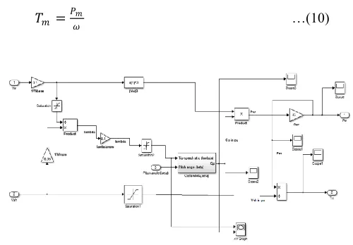
Mechanical torque T
mreferred to as the ratio of
mechanical power to turbine speed as given by [4]
𝑇𝑚= 𝑃𝑚
𝜔 …(10)
Fig. 3 Wind Turbine Model
International Journal of Research (IJR)
e-ISSN: 2348-6848, p- ISSN: 2348-795X Volume 2, Issue 4, April 2015Available at http://internationaljournalofresearch.org
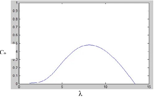
λ
Fig. 4Curve of CP for β = 0ﹾ
Shaft and gearbox together makes the drive train system. Here, two-mass model of the drive train system is used which is given by [5]
Tt - Tsh = 2*Ht*
dωt
dt
…(11)
dθsta dt
=
ωt−ωr
Webase …(12)
Tsh = [θsta *Kss + Kd *(Wt-Wr)] …(13) Tbase = W ebasePnom …(14)
Tm = Tbase* Tsh …(15)
Where Tt and Tshare output torque of the turbine and shaft torque respectively. Ht is turbine inertia constant.θstais shaft twist angle and Kss, ⍵t are shaft stiffness coefficient and angular speed of the wind turbine respectively.Pnom refers to the rated mechanical power of wind energy system, Webaserefers the electrical base speed and Tbase as the base torque of wind turbine.
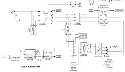
Simulink model of the Drive Train is shown in the figure below.
Fig. 5 Drive Train Model
B. Pitch Angle Controller
The pitch angle controller model as shown in Fig5, is useful when wind speed is high and the generator speed can no longer be controlled by increasing the generated power because of capacity constraints of generator and converters/inverters. Therefore the blade pitch angle is adjusted to limit the aerodynamic efficiency of the rotor. This prevents the rotor speed becoming too high. The pitch angle should be varied to balance the electrical and mechanical power [6].
Fig. 6 Pitch Angle Controller Model
Doubly-Fed Induction Generator (DFIG) is connected to the grid via its two converters which is the Rotor Side Converter (RSC) and Grid Side Converter (GSC).DFIG stator is connected to the grid directly while the rotor is connected via the converters to the grid.Pulse Width Modulation (PWM) generator is used for generating and supplying the pulse into the convertors. Choke is used here in order to limit the high starting current from the generator.
The Simulink model thus drawn for the purpose is shown in Fig. 7.
International Journal of Research (IJR)
e-ISSN: 2348-6848, p- ISSN: 2348-795X Volume 2, Issue 4, April 2015Available at http://internationaljournalofresearch.org
Fig. 7 DFIG with its converters
III. MODEL OF THE POWER GRID
The single line diagram of test system used in this study is illustrated in Figure 3. The grid model consist of a 33 kV, 60 Hz, grid supply point, feeding a 25 kV distribution system through a 1000 MVA, 33/25 kV step down transformer, which is fed into a 460V system through 1000 MVA, 25kV/460V step down transformer. There is astatic load of 500 MW at B460 bus. The line of 25 kV, 30kilometres is shown as a nominal-Π line. The DFIG based wind turbine is of 1.5 MW.The speed of the wind is variable with gradual increase in slope [7].
Fig. 8 Single line diagram for the system
The DC link voltage of the DFIG is taken as 1000 mF. The system is studied for 0.4secs. For providing voltage sag compensation, a DVR is connected as a series device for voltage compensation at the sending end bus (460 V). Here in this model, a nominal Pi-Line of 30 km is used.
The DFIG is thus connected to the power grid via the Point of Common Coupling (PCC) and a three phase or symmetrical fault is created in the load side.The Simulink model is shown in Fig. 9.
Fig. 9 DFIG connected to the grid
IV. STATICSYNCHRONOUSCOMPENSATOR
Static Synchronous Compensator (STATCOM) is a FACTS device consisting of a coupling transformer, Voltage Source Converter (VSC) and a dc energy storage device connected in shunt via the coupling transformer to the distribution network. DC energy source which is present is converted into three phase AC output voltage by VSC across the storage device. It is used for generating and absorbing the reactive power by continuously varying the amplitude ofthe converter voltage. With respect to the line bus voltage, a controlled current flows in between the tie reactance which is between the STATCOM and the distribution network enabling the STATCOM to mitigate the fluctuations in voltage such as swells, sags, transient disturbances etc and for providing smooth voltage regulation.
Here in this paper, a 3-level cascaded multilevel converter based STATCOM is used for mitigating the voltage sag [8].
Fig. 10 STATCOM Model
International Journal of Research (IJR)
e-ISSN: 2348-6848, p- ISSN: 2348-795X Volume 2, Issue 4, April 2015Available at http://internationaljournalofresearch.org
Fig. 11 Multilevel Inverter
The STATCOM model [9] thus generated is integrated to the existing model in the load side for voltage mitigation purpose. The model thus produced is as shown in Fig. 12.
Fig. 12 Grid connected DFIG with STATCOM
V. SIMULATIONRESULTSANDDISCUSSION
The DFIG based system is connected to the grid and the real and reactive power of the system isas shownbelow. The system is analysedunder 3-phase fault and in not going to affect the DFIG active power output, the initial fluctuations of the DFIG as shown in figure 13 is due to the wind speed variations and at 1.5 MW,its becoming almost constant.
Fig. 13 Active power output of DFIG
Reactive power as shown in Fig. 14 is almost equal to zero, thus making it a free flowing system and the power factor closely equals to 1.
Fig. 14 Reactive power output of DFIG
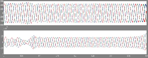
Fig. 15 and Fig. 16 shows the Stator voltage and current, Rotor voltage and current respectively.
Fig. 15 Stator voltage and current waveform
Fig. 16 Rotor voltage and current waveform
International Journal of Research (IJR)
e-ISSN: 2348-6848, p- ISSN: 2348-795X Volume 2, Issue 4, April 2015Available at http://internationaljournalofresearch.org
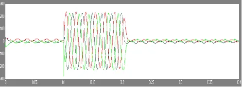
A STATCOM is connected at the load end and it compensates for the voltage needed for the sag compensation and the obtained result is given below.
Fig. 18 System after voltage mitigation
STATCOM is thus injecting the voltage needed for restoring the system to the normal operating condition.
Fig. 19 STATCOM voltage injected into the system
VI. CONCLUSION
This paper presents the Low Voltage sag Ride-Through (LVRT) capability of wind turbine. One of the most simplest and successful method for voltage sag compensation is to integrate the DFIG-based wind turbine to the power grid for the duration of grid disturbances. The application of STATCOM indetailed investigated and studied in this paper to achieve uninterrupted operation of DFIG-based wind turbine during three phase or symmetrical fault conditions.
Without using STATCOM, the voltage at Point of Common Coupling (PCC) is dropping about 50% of the system voltage.So for improving the voltage profile, STATCOM is implemented in the paper.
However, varying wind speed is considered here. Different constant wind speed can be considered and the results obtained can thus be compared for future references.Maximum Power Point Tracking (MPPT) Technique can be implemented for best efficiency from the system.
APPENDIX
DFIG
Nominal power: 1.5 MVA Nominal voltage (LL): 460 V Nominal Frequency: 60 Hz Pair of poles: 2
Stator resistance and inductance: 0.01965, 0.0397pu Rotor resistance and inductance: 0.01909 0.0397pu Dc link capacitance: 1000 mF
TRANSFORMER
Nominal power: 1000 MVA Nominal Frequency: 60 Hz Ratio: 25000/460 V, Δ/Y
GRID
Nominal power: 1000 MVA Nominal voltage (LL): 25 kV Nominal Frequency: 60 Hz Source Impedance: 0.0001 Ω
TURBINE CONSTANTS
International Journal of Research (IJR)
e-ISSN: 2348-6848, p- ISSN: 2348-795X Volume 2, Issue 4, April 2015Available at http://internationaljournalofresearch.org
REFERENCES
[1] R. Saidur et al., "Environmentalimpact of wind energy," Renewable Sustainable Energy Reviews, vol. 15, pp. 2423-2430, 2011.
[2] S. Shams et al., "Applying the CHP method on small-scale on-site power generation," in Clean Energy and Technology (CEAT), 2013
[3] Min MinKyaw, V.K. Ramachandaramurthy, ―Fault ride through and voltage regulation for grid connected wind turbine,‖.Renewable Energy, vol. 36, pp. 206-215, 2011.
[4] S. Romphochai, P. Kumkratug, ―Modeling and Simulation DFIG Based on Wind Energy Conversion System in MATLAB/SIMULINK,‖ Proc. of the Second Intl. Conf. on Advances in Electronics and Electrical Engineering — AEEE 2013, pp. 42-45.
[5] H. Li et al., ―Analysis and Estimation of Transient Stability for a Grid-Connected Wind Turbine,‖ Renewable Energy An International Journal., vol. 36, pp. 1469-1476, Aug. 2010.
[6] T.Salma, R.Yokeeswaran, ―Pitch Control of DFIG based Wind Energy Conversion System for Maximum Power Point Tracking,‖ International Journal of Advanced Research in Electrical, Electronics and Instrumentation Engineering, Vol. 2, Issue 12, pp. 6373-6381, December 2013.
[7] M. J. Ghorbanian, F. Goodarzvand et al., ‖Mitigating Voltage Sag by Implementing STATCOM on DFIG-based Wind Farms Connected to a Power System,‖ 2014 4th International Conference on Engineering Technology and Technopreneuship (ICE2T), pp. 131-136.
[8] M. J. Ghorbanian, ―Mitigating Voltage Sag by Implementing STATCOM on DFIG-based Wind Farms Connected to a Power System,‖ 4th International Conference on Engineering Technology and Technopreneuship (ICE2T), 2014, pp. 131-136.
[9] Spyros I. Gkavanoudis, Charis S. Demoulias,
grids employing DVR and supercapacitor energy storage,‖ Electrical Power and Energy Systems 68 (2015) 356–363.