Performance Investigation of Active Harmonic
Power Filter Using PWM Methods
S.V.Purnima
1, C.Gomathi
2, S.Sathya
3, T.Snekapriya
4PG scholar Department of EEE, Bannari Amman Institute of Technology, Sathyamangalam,Tamilnadu,India.
PG scholar Department of EEE, Bannari Amman Institute of Technology, Sathyamangalam,Tamilnadu,India.
PG scholar Department of EEE,Bannari Amman Institute of Technology, Sathyamangalam,Tamilnadu,India.
PG scholar Department of EEE, Bannari Amman Institute of Technology, Sathyamangalam,Tamilnadu,India.
Abstract - Interference due to harmonics, and generated by power electronic devices, has become a serious problem, because converters are nowadays more and more frequently used in transmission and distribution systems and in power plants. The most natural, suitable way to solve these problems is the introduction of filtering actions. Passive LC filters have long been used to absorb harmonic current of non-linear loads. Due to some disadvantages of passive filters the concept of active filters were proposed. There are so many different controlling algorithms and topologies available for active filter. Here Pulse Width Modulation based topology is used. This paper analyzes the comparative merits of Sinusoidal Pulse Width Modulation (SPWM) and Variable Index Pulse Width Modulation (VIPWM) techniques and the suitability of these techniques in a Shunt Active Filter. The objective is to select the scheme which provides improved output current harmonics. Simulation Results are presented in MATLAB/SIMULINK. Results show that the proposed method is effective cancel out the undesirable harmonics.
Key words: Shunt Active Power Filter, Pulse Width Modulation, voltage source inverter, power quality.
I. INTRODUCTION
II. ACTIVE POWER FILTER
Active power filter compensate current Harmonics by injecting equal-but-opposite harmonic compensating current. In this case the active power filter operates as a current source injecting the harmonic components generated by the load but phase shifted by 180o. This principle is applicable to any type of load considered a harmonic source.
A. Basic principle of active power filter
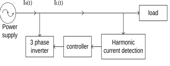
The basic principle of active power filter consists of three steps it is shown in Figure 1. Firstly the current of the load or voltage of the source is detected, and its harmonic component is then calculated by the harmonic current detecting circuit. The inverter is controlled to output the compensation current whose polarities are inversed with the harmonic currents. The active power filter (APF) is a popular approach for cancelling the harmonics in power system. The main component in the APF is the control unit. The control unit is mainly divided into two parts as follows
Harmonic Extraction Technique: Harmonic extraction is the process in which, reference current is generated by using the distorted waveform. Many theories have been developed such as p-q theory (instantaneous reactive power theory), d-q theory, frieze controller, PLL with fuzzy logic controller [3], neural network etc.. Out of these theories, more than 60% research works consider using p-q theory and d-q theory due to their accuracy, robustness and easy calculation. Current Modulator: Current modulator is mainly used to provide the gate pulse to the active power filter (Inverter). There are many techniques used for giving the gating signals to PWM VSI such as sinusoidal PWM, triangular PWM, hysteresis current controller, adaptive hysteresis current controller, space vector modulation and space vector with hysteresis current controller etc.
3 phase
inverter
Harmonic
current detection
controller
Power
supply
load
Is(t)
I
L(t)
Fig. 1 Active power filter
III. HARMONIC MITIGATION METHODS IN SAPF USING PWM TECHNIQUE
Theharmonic detection method is the part of the APF’s control that has the capability of determining specific attributes of the harmonics (frequency, amplitude, phase, time of occurrence, duration, energy) from an input signal which can be voltage or current. The most common and popular technique of digital pure-sine wave generation is pulse-width-modulation (PWM). The PWM technique involves generation of a digital waveform, for which the duty-cycle is modulated such that the average voltage of the waveform corresponds to a pure sine wave. The simplest way of producing the PWM signal is through comparison of a low-power reference sine wave with a triangle wave using these two signals as input to a comparator, the output will be a 2-level PWM signal. This PWM signal can then be used to control switches connected to a high-voltage bus, which will replicate this signal at the appropriate voltage The PWM techniques are classified as
Single pulse width modulation Multi pulse width modulation Sine pulse width modulation
A. Single pulse width modulation
In single pulse-width modulation control, there is only one pulse per half cycle and the width of the pulse is varying to control the output voltage. The gating signals are generated by Convert the reference signal to the square wave signal. This process is obtained by inter the reference signal to the zero-crossing circuit witch consider the positive part of the input signal is positive part of the output signal(square wave) and the negative part of the input signal is negative part of the output signal
.
B. Multi pulse width modulation
The harmonic content can be reduced by using several pulses in each half-cycle of output voltage. The gating signals are produced by comparing reference signal with triangular carrier wave. The frequency of the reference signal sets the output frequency (fo) and carrier frequency (fc ) determine the number of pulses per half cycle.
C. Sine pulse width modulation
Instead of maintaining the width of all pulses the same as in the case of uniform pulse width modulation, the width of each pulse is vary in proportion to the amplitude of a sine wave evaluated at the center of the same pulse. The distortion factor and lower-order harmonics are reduced scientifically. The gating signals are generated by comparing a sinusoidal reference signal with a triangular carrier signal of frequency fc. SPWM is commonly used in industrial applications. The frequency of reference signal (fr), determine the converter output frequency (fo) and its peak amplitude (Ar) controls the modulation index, M. The number of pulses per half cycle depends on the carrier frequency. This SPWM technique can be classified into two types
Uni-Polar SPWM Technique Bi-Polar SPWM Technique
D. Variable index pulse width modulation
In the variable index pulse width modulation triangular signal contains the information related to the output signal and also its amplitude will vary in proportion to the amplitude of the reference signal. In fact, the modulation index changes in proportion to the amplitude of the reference signal, hence it is termed VIPWM.
Fig.2 Variable index pulse width modulation technique
IV. PROPOSED SYSTEM AND DESCRIPTION
dependent to the motioned methods. The method is proposed in this project is modified modulation which is based on the variable index and the integral of the output signal provided from the phase detection stage. The obtained triangular signal contains the information related to the output signal and also its amplitude will vary in proportion to the amplitude of the reference signal.
A. Identification stage
The reference signal is generated in the identification section. This signal defines the current that should be produced by the three phase inverter of SAF. There are two methods for generating the reference signal are time domain and frequency domain. The time domain methods such as d–q transformation or synchronous rotating reference frame, p–q transformation or instantaneous reactive power, and symmetrical components transformation, are based on measurements and transformation of the three-phase quantities. The main advantage of the time domain methods over the frequency domain methods, which are based on the FFT, is their fast responses. The frequency domain methods provide accurate individual and multiple harmonic load currents detection. Time domain methods Such as instantaneous reactive power methods suffer from dependency on source voltage harmonics. When the source is non-sinusoidal the instantaneous reactive power theory is not suitable. In this project a frequency domain approach based on Band Reject Filter (BRF) is employed. In this approach, the line current signal is passed through a BRF having a centre frequency equal to power system fundamental frequency. The output signal contains all harmonics except the fundamental, so it can be a suitable reference signal for compensation. Moreover, the BRF method does not require any voltage sensor, in contrast to the instantaneous reactive power method in which voltage sensors are needed, so it can be more economical.
B. Modulation stage
In previously developed SAFs in which the PWM techniques are used, the reference signal is compared with a triangular signal. Such triangular signals have no information related to the output signal. In the proposed method the triangular signal is derived from the integral of reference signal so it will be an intelligent signal. The obtained triangular signal contains the information related to the output signal and also its amplitude will vary in proportion to the amplitude of the reference signal. The modulation index changes in proportion to the amplitude of the reference signal. In the positive half cycle, at first the integral of the reference current is performed, then the triangular wave of the integrator output is compared with the reference current. So long as the reference current is greater than the integrator output, transistor q1 is on and transistor q4 is off. When these two signals are equal, the integrator becomes reset, and as long as the integrator output is zero, q1 is off and q4 is on. When output increases q1 starts to conduct and q4 ceases. This process continues until the positive half cycle ends. During the negative half cycle, as long as the integrator output is greater than the reference signal, q4 conducts and q1 does not. When two signals are equal, the integrator output is zero in that time q1 is on and q4 is off.
C. Inverter
In this paper Shunt active power filter is designed to compensate the current, so that the Current source inverter is the appropriate choice, but it has some disadvantages, like requirement of high cost current sensors. Therefore, using VSI is preferred compare with CSI. The current reference signals produced in the identification part of the system should be converted to voltage reference signals by a suitable method. Then, the VSI must create these signals for system. The inverter is connected to the grid through an inductance; the Shunt active power filter should have capacitive effect to prevent the reduction of filter capability.
V. SIMULATION AND RESULTS
Fig.3 Pulse generated using SPWM Technique
Fig.4 Pulse generated using Variable Index Pulse Width Modulation Technique
Fig.6 Line current THD value with SPWM Technique
Fig.7 Line current THD value with VIPWM Technique
VI. CONCLUSION
In this paper, the ability and the performance of shunt active Filters (SAFs) were analysed with the Sinusoidal Pulse Width Modulation (SPWM) and Variable Index Pulse Width Modulation (VIPWM) techniques. From simulation result and comparative merits of Sinusoidal Pulse Width Modulation (SPWM) and Variable Index Pulse Width Modulation (VIPWM) techniques we can conclude that VIPWM techniques is very effectively reduces THD level compared with SPWM technique.
REFERENCES
[1] Bojoi R.I , Limongi L.R, Roiu .D, and Tenconi.A, “Enhanced power quality control strategy for single-phase inverters in distributed generation systems,” IEEE Trans.Power Electron.,vol. 26, no.3, pp. 798–806, Mar. 2011.
[2] Bharanikumar.R ,Nirmalkumar.A , Yazhini.A.C “Modeling and Simulation of Wind Turbine Driven Permanent Magnet Generator with New MPPT Algorithm” Asian Power Electronics Journal, Vol. 4 No.2 August 2010:52-58
[3] Dos Reis FS, Ale JAV, Adegas FD, Tonkoski R, Slan S, Tan K. Active shunt filter for harmonic mitigation in wind turbines generators. Power Electr Special Conf 2006:1–6.
[4] Gaillard A, Poure P, Saadate S, Machmoum M. “Variable speed DFIG wind energy system for power generation and harmonic current mitigation” Renew Energy Int J 2009:1545–53.
[5] Krause PC. Analysis of electric machinery. New York, NY: McGraw-Hill BookCompany; 1986
[6] Kholy E.E, Sabbe.A, Hefnawy.A, Hamdy.M “Three-phase active power filter based on current controlled voltage source inverter” Int J Electr Power Energy Syst 2006; 28 (1): 537–547.
[8] Kusuma Lath.Y, Saibabu.C.H, Obulesh.Y.P “Control Strategy for Three Phase Shunt Active Power Filter with Minimum Current Measurements” Int J Electr and Comp Engg 2011;1(1): 31 – 42.
[9] Mcgrath B. P,Holmes D. G, and Galloway J. J. H, “Power converter line synchronization using a discrete Fourier transform (DFT) based on a variable sample rate,” IEEE Trans. Power Electron., vol. 20, no. 4, pp. 877-884, Apr. 2005.
[10] Naimish Zaveri , Ajitsinh Chudasama “Control strategies for harmonic mitigation and power factor correction using shunt active filter under various source voltage conditions” Int J Electr Power Energy Syst 2006; 42 (1): 661–671.
[11] Weihao Hu, Zhe Chen, Yue Wang, and Zhaoan Wang“Flicker Mitigation by Active Power Control of Variable-Speed Wind Turbines With Full-Scale Back-to-Back Power Converters” IEEE transactions on energy conversion, vol. 24, no. 3, september 2009.
[12] Zhou Zhongfu, Liu Yanzhen. Pre-sampled data based prediction control for active power filters. Int J Electr Power Energy Syst 2012;37(1):13– 22.
BIOGRAPHY
S.V.Purnima received her BE Degree in Electrical & Electronics Engineering from Avinasilingam University, Coimbatore in May 2012. Currently she is pursuing her ME Degree in Power Electronics & Drives from Anna University, Chennai. Her research interest area is power quality and Wind Energy Conversion System .She has published papers in National Conference and international conference.
C.Gomathi received her BE Degree in Electrical & Electronics Engineering from Karpagam University, Coimbatore in May 2012. Currently she is pursuing her ME Degree in Power Electronics & Drives from Anna University, Chennai. She has published papers in National Conference and international conference. Her research interest includes power electronics and multi level inverter
S.Sathya received her BE Degree in Electrical & Electronics Engineering from Anna University, Coimbatore in May 2012. Currently she is pursuing her ME Degree in Power Electronics & Drives from Anna University, Chennai. Her research interest includes power electronics and electrical machines. She has published papers in National Conference and international conference.