R E S E A R C H
Open Access
Structured root-LDPC codes and PEG-based
techniques for block-fading channels
Andre G.D. Uchoa
†, Cornelius T. Healy
*†and Rodrigo C. de Lamare
Abstract
In this work, we propose structured root-low-density parity-check (LDPC) codes and design techniques for
block-fading channels. In particular, quasi-cyclic root-LDPC codes, irregular repeat-accumulate root-LDPC codes and controlled doping root-LDPC codes based on progressive edge growth (PEG) techniques for block-fading channels are proposed. The proposed root-LDPC codes are both suitable for channels underF=2, 3 and 4 independent fading per codeword. The performance of the proposed codes is investigated in terms of frame error rate (FER). The
proposed root-LDPC codes are capable of achieving the channel diversity and outperform standard LDPC codes. For block-fading channel withF=2 our proposed PEG-based root-LDPC codes outperform PEG-based LDPC codes by 7.5 dB at a FER close to 10−3.
Keywords: LDPC; Root-LDPC; PEG; Repeat-accumulate; Block-fading; Controlled doping
1 Introduction
The most recent IEEE wireless local area network (WLAN) 802.11ad standard [1] argues that to achieve high throughput the devices must operate with LDPC codes [2, 3]. As wireless systems are subject to multi-path propagation and mobility, these systems are charac-terized by time-varying channels with fluctuating signal strength. In applications subject to delay constraints and slowly-varying channels, only limited independent fad-ing realizations are experienced. In such conditions also known as non-ergodic scenarios, the channel capacity is zero since there is an irreducible probability, termed out-age probability [4], that the transmitted data rate is not supported by the channel. A simple and useful model that captures the essential characteristics of non-ergodic channels is the block-fading channel [5, 6]. It is especially important in wireless communications with slow time-frequency hopping (e.g. cellular networks and wireless local area networks) or multi-carrier modulation using orthogonal frequency division multiplexing (OFDM) [7]. Codes designed for block-fading channels are expected to achieve the channel diversity and to offer excellent coding gains.
*Correspondence: [email protected] †Equal contributors
CETUC - Pontifical Catholic University of Rio de Janeiro - PUC-RJ, R. Marques de Sao Vicente, 225 - Ala Kennedy, 22451-900 LRio de Janeiro, Brazil
1.1 Prior and related works
A family of LDPC codes called root-LDPC for block-fading channels with F = 2 fading per codeword was proposed in [7]. Root-LDPC codes are able to achieve the maximum diversity of a block-fading channel and have a performance near the limit of outage when decoded using the Sum Product Algorithm (SPA). Root-LDPC codes are always designed with code rateR = 1/F, since the Sin-gleton bound determines that this is the highest code rate possible to obtain the maximum diversity order [7]. Y. Li and M. Salehi in [8] have presented the construction of structured root-LDPC codes by means of tiling circu-lant matrices, i.e. by designing quasi-cyclic low-density parity-check (QC-LDPC) codes [9]. It is also shown that the QC-LDPC codes can perform as well as randomly generated root-LDPC codes over block-fading channels. Uchoa et al. in [10] proposed a PEG-based algorithm to design LDPC codes with root-check properties, thus pro-viding root-LDPC codes with larger girths. A strategy that imposes constraints on a PEG-based algorithm which are required by root-LDPC codes was devised. This approach has provided better performance in terms of FER and BER than the works in [7, 8]. Duyck et al. in [11] proposed the design of a random LDPC codes which are able to achieve full diversity in block-fading channels with F = 2 fad-ings. Healy and de Lamare in [12] extended the work in [11] for the case of block-fading channels with F = 3
and F = 4 fading per block transmitted. Uchoa et al. in [13] proposed iterative detection and decoding (IDD) algorithms for multiple-input multiple-output (MIMO) systems operating in block fading and fast Rayleigh fading channels.
1.2 Contributions
We propose in this work three structures to design root-LDPC codes which are quasi-cyclic, repeat and accumulate and controlled doping. Preliminary results toward PEG-based algorithm to design QC-LDPC codes with root-check properties for block-fading channel with F = 3, 4 fading per codeword were reported in [14]. Here, in this work we present a more detailed analysis of quasi-cyclic root-check-based LDPC codes. Furthermore, initial results for a PEG-based algorithm to design irregular repeat-accumulate (IRA) LDPC codes with root-check properties for block-fading channels were discussed in [15]. Here, we present a more detailed analysis of irregular repeat-accumulate and accumulate IRAA root-check structure for F = 2, 3 independent fading.
In general, the parity check bits of root-LDPC codes are not in full diversity. Boutros in [16] proposed a controlled doping via high order root-LDPC codes, which are able to guarantee full diversity for the parity check bits. Such a design becomes really important when iterative detection and decoding (IDD) is used in spread spectrum [17, 18] and MIMO systems [19–21]. In IDD systems, the detector and the decoder exchange their extrinsic information in an iterative way. Therefore, if the parity bits are not in full diversity, the overall IDD system performance will lead to a degradation in terms of bit error rate (BER) instead of improvements as stated in [17].
In this paper, we also propose a novel full diversity controlled doping root-check RA-based LDPC codes for block-fading channels ofF=2, 3, 4 fading which includes the code ratesR= 12,R= 13andR= 14.
The main contributions of this work can be summarized as follows:
• Root-LDPC codes for block-fading channels
including structured, unstructured, controlled doping and RA designs are developed.
• New PEG-based algorithms for several root-LDPC code structures are presented.
• A comprehensive simulation study of root-LDPC codes and design algorithms is detailed.
The rest of this paper is organized as follows. In Section 2, we describe the system model. In Section 3, we discuss the prior and related works on the design of root-LDPC codes and their structure. In Section 4, the proposed PEG-based quasi-cyclic root-LDPC codes,
irregular repeat-accumulate root-LDPC codes and con-trolled doping root-LDPC codes and their structure are presented. In Section 5, a discussion of which a root-LDPC code is more appropriate for a specific scenario is provided. In Section 6, the simulation results are shown, while Section 7 concludes the paper.
2 System model
Consider a block-fading channel, whereFis the number of independent fading blocks per codeword of lengthN. Following [8], thetth received symbol is given by:
rt=hfst+ngt, (1)
where 1 ≤ t ≤ N, 1 ≤ f ≤ F,f andt are related by
f = FNt, where φ returns the smallest integer not smaller than φ,hf is the real Rayleigh fading coefficient of the fth block, st is the transmitted signal, and ngt is
additive white Gaussian noise with zero mean and vari-anceN0/2. In this paper, we assume that the transmitted
symbols st are binary phase shift keying (BPSK) modu-lated. We assume that the receiver has perfect channel state information and that the SNR is defined asEb/N0,
whereEbis the energy per information bit. The informa-tion transmission rate isR=K/N, whereKis the number of information bits per codeword of lengthN. For the case of a block-fading channel, we consider R = 1/F, since then it is possible to design a practical diversity achiev-ing code [8]. The performance of a communication system in a non-ergodic block-fading channel can be investi-gated by means of the outage probability [4], which is defined as:
Pout=P(I<R), (2) where P(φ) is the probability of event φ and I is the mutual information. The mutual informationIG, for Gaussian channel inputs is [8]:
IG= 1
F
F
f=1 1 2log2
1+2REb N0
h2f
, (3)
so that an outage occurs when the average mutual mation among blocks is smaller than the attempted infor-mation transmission rate.
3 Root-LDPC codes
information node in question. Thus, the information node can be recovered provided at least one fading coefficient is large enough. Since for each information node there is a check node for all other fading coefficients, the root-checks appear as identity matrices in the parity-check matrix of the root-LDPC codes. The properties offered by the root-check node structure are full single-iteration con-vergence on the noise-free block binary erasure channel and thus full diversity performance on the block fading channel of (1) [7].
In this section, the parity check matrix of the most rel-evant root-LDPC codes are discussed. The number of fadings considered areF = 2, 3 and 4 which correspond to code ratesR= 12,13and14.
3.1 Random root-LDPC codes
Here, we will introduce some definitions and the notation adopted in this work. The binary LDPC code in systematic form is specified by its parity-check matrixH:
H=[IN−K P] , (4)
whereIN−K is the identity matrix of size (N-K) andPis an (N-K)-by-K matrix. Then the generator matrix for the code is:
G=PT IK
, (5)
where(·)Trefers to the transpose operation.
The variable node degree sequence Ds is defined to be the set of column weights of H as designed and is prescribed by the variable node degree distributionλ(x)
as described in [22]. Moreover, Ds is arranged in non-decreasing order. The first proposed root-LDPC codes were devised by Boutros et al. in [7]. Therefore, the gen-eral structure of the parity-check matrix for a random root-LDPC code forF=2 can be defined as
1i 2i 1p 2p
where the nodes (1i and 2i) represent the information symbols that are sent over two independent fadings, the same happens to nodes (1pand 2p) which are the parity symbols; (1cand 2c) are the check nodes. In the parity-check matrixH, there are eight sub-matrices of sizeN4×N4.
I is an identity sub-matrix, 0 is a null sub-matrix, H1i andH2iare sub-matrices of Hamming weight 2 connected to the information symbols, H1p andH2p are also sub-matrices of Hamming weight 3 connected to the parity
symbols. In a similar fashion, it can be devised for the case ofF=3 as stated in [7].
3.2 Quasi-cyclic root-LDPC codes
Following the idea of Boutros et al. in [7], Li and Salehi in [8] devised a quasi-cyclic root-LDPC codes. The parity-check matrixH of a QC-LDPC code can be defined as [23]:
whereHij is ann×n circulant or all-zeros matrix, and
candware two positive integers with c < w. The null space ofHgives a QC-LDPC code overGF(2)of length
N=wn. The rank ofHis at mostcn. Hence the code rate is at leastww−c.
For the case of quasi-cyclic root-LDPC codes the parity-check matrix follows the same idea as (6), although the sub-matrices become a set of quasi-cyclic matrices. Con-sequently,Ibecomes
where each Ii,j is a circulant permutation matrix, a cir-culant matrix with row and column weights 1. Each 0
Eqs. (8), (9) and (10) are for a regular QC-root-LDPC code C(3, 6). QC-root-LDPC codes were proposed with the aim of providing fast encoding and to save memory to store the generator matrix. Li and Salehi in [8] have shown that the QC-LDPC codes can perform as well as ran-domly generated root-LDPC codes [7] over block-fading channels.
3.3 Unstructured full-diversity LDPC codes
Duyck et al. in [11] proposed the design of random LDPC codes which are able to achieve full diversity in block-fading channels withF = 2 fading. The principle proposed in [11] is to allow a small reduction in coding rate in order to produce random codes that may achieve the diversity of the channel, i.e. the error rate achieved by the code behaves as SNR12. However, as these codes achieve the desired error rate performance but do not have the maximal rate allowed by the Singleton bound, they may be called full-diversity codes but not blockwise maximum-distance separable (MDS) codes [24]. Specif-ically, the codes of [11] place the requirements that the nodes associated with the information bits have weight
dv = 2 and do not participate in any stopping sets. The code rate isR∼=0.5.
The design of such LDPC codes was achieved by requir-ing that the number of check nodes in the graph be greater thanN2, i.e. that the rate be less than12, and that the weight of the first N2 variable nodes is 2 and that the graph be constructed by the PEG algorithm [25], which maximizes cycle length at each placement, ensuring under these con-ditions no cycles in the sub-graph comprised of the first
N
2 variable nodes alone. The requirement of recoverability
for the worst-case scenario is equivalent to the require-ment that no information variable node vinf ∈ Vinf, affected by α1, is an element of any stopping set found
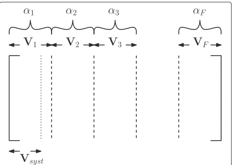
among the variable nodes V1∪ {V2∪V3 ∪ · · ·VF}\Vi. This requirement must hold for alli = 2,· · ·,F for the information variable nodes to be recoverable on the block binary erasure channel and thus for the code to achieve full diversity on the block fading channel. The parity-check matrix for this general case, with variable node subset labels and the corresponding fading coefficients are given in Fig. 1.
3.3.1 Unstructured full-diversity rate13
In (11), a code graph is shown for the case of F = 3 fading per codeword [12] by means of imposing null matrices on the parity-check matrix, along with restric-tions on the cycles present in the sub-graphs of the code. The structured matricesHα,1Hα2
andHα,2Hα3
must be constructed by the PEG algorithm, as in [11], ensur-ing the extrinsic connections toV2andV3, respectively.
The constraints on the code sub-graphs result in the vari-able nodes ofV1having weight 4. The distribution of the
Fig. 1Parity-check matrix unstructured general case. Parity-check matrix for the general case
nodes inV2 andV3is unconstrained and may be
irreg-ular. In addition to this weight constraint, each of the sub-matricesHα,1Hα2
andHα,2Hα3
are constrained to have a rate less than 12, and so the final graph will have a rate less than 13.
α1 α2 α3
HBF3=
Hα1,1 Hα2 0
Hα1,2 0 Hα3
(11)
3.3.2 Unstructured full-diversity rate14
The code graph achieving the requirements on stopping sets among V1,· · ·,V4 containing information variable
nodes is presented in (12) [12]. We can see that with each additional fading coefficient considered, a straight-forward graph expansion is carried out, effectively nesting theF−1 diversity achieving graph in the code capable of full-diversity performance on the channel with F fading coefficients.
α1 α2 α3 α4
HBF4=
⎡
⎣HHαα11,1,2 H0α2 H0α3 00
Hα1,3 0 0 Hα4 ⎤
⎦ (12)
4 Proposed PEG-based root-LDPC codes
In this section, the proposed PEG-based root-LDPC codes are discussed. The number of fadings considered areF =
2, 3 and 4 which correspond to code ratesR= 12,13and14.
4.1 QC PEG-based root-LDPC codes
Preliminary results on the design of a PEG-based quasi-cyclic root-LDPC codes for block-fading channel withF=
a significant performance in terms of FER with respect to the theoretical limit. These codes can save up to 3 dB in terms of signal to noise ratio to achieve the same FER when compared to other codes.
A root-LDPC code requires a designer to divide both variable and check nodes inFequal parts. Following the root-check-based structure reported in [7], the parity-check matrix becomes:
H=[S1P1,· · ·,SFPF] , (13)
where the subscripts represent the variable nodes (infor-mation and parity, respectively) under a specific fading block. The parity-check matrix of (13) can be reordered to
H=[S1,· · ·,SFP1,· · ·,PF], with the blocksSiassociated with information nodes and the blocksPiassociated with parity nodes. In order to obtain the generator matrix, the sub-matrixBformed by parity matricesP1,· · ·,PF must be a non-singular matrix, which means it is invertible underGF(2)[8].
To design a practical code forF = 3 which is able to achieve the channel diversity, the highest possible rate of such a code isR = 1F = 13. As a result, the parity-check matrix forR= 13can be defined as in (14),
1i 2i 3i 1p 2p 3p
H=
⎡ ⎢ ⎢ ⎢ ⎢ ⎢ ⎢ ⎣
I0,0 H0,1 0 0 0 0 H0,6 H0,7 H0,8
I1,0 0 H1,2 0 0 0 0 H1,7 H1,8
H2,0 I2,1 0 0 0 0 0 0 H2,8
0 I3,1 H3,2 H3,3 0 0 0 0 0
H4,0 0 I4,2 H4,3 H4,4 0 0 0 0
0 H5,1 I5,2 H5,3 H5,4 H5,5 0 0 0 ⎤ ⎥ ⎥ ⎥ ⎥ ⎥ ⎥ ⎦ ,
(14)
where the n × n matrices Hij are circulant matrices of column and row weight as required by the degree distribution of the code, Iij are n × n circulant per-mutation matrices, while 0 is an all-zeros matrix. The notationIij was used to reinforce that such connections are the root-check connections [7]. The restrictions that should be imposed are only the Iij to be placed in the positions described in (14) and the upper and down triangular sub-matrices in the parity part, B, of H. In order to perform a PEG-based design, the only restric-tion imposed is that the sub-matricesIij and the upper and down matrices of (14) are kept. The other sub-matrices can be placed following a quasi-cyclic PEG-based algorithm.
The parity-check matrix forF=4 with code rateR= 14
is structured similarly to (14), and the same restrictions may be imposed to the design to construct a PEG-based QC-root-LDPC code for this scenario.
4.1.1 Proposed design algorithm
Here, we introduce some definitions and notations. Then, we present the pseudo-code of our proposed algorithm for PEG-based quasi-cyclic root-LDPC codes. The block-fading channels withF = 3 andF = 4 are considered. In extending to a greater number of fadings, F > 4, the general structure presented is maintained, with the information variable nodes for each fading possessing root-check identity matrices connecting to parity variable nodes in each of the other fading blocks only, ensur-ing the upper and lower triangular sections of parity bits observed in (14). The placement of the remaining cyclic sub-matrices is required to maintain this relationship and provide satisfactory final code degree distribution. The LDPC code is specified by its sparse parity-check matrix
H =[A | B], where A is a matrix of size M-by-K, and
B is an M-by-M matrix. The generator matrix for the code isG = (B−1A)T|IK
, IK is an identity matrix of sizeK.
The variable node degree sequence Ds is defined as the set of column weights of the designedHand is pre-scribed by the variable node degree distributionλ(x)as described in [22]. Moreover, Ds is arranged in a non-decreasing order. The proposed algorithm, called QC-PEG root-LDPC, constructsHby operating progressively on variable nodes to place the edges required byDs. The variable node of interest is labelledvj and the candidate check nodes are individually referred to as ci. The PEG root-LDPC algorithm chooses a check nodecito connect to the variable node of interestvj by expanding a con-strained sub-graph fromvjup to maximum depthl. The set of check nodes found in this sub-graph are denoted
Nl
vjwhile the set of check nodes of interest, those not
cur-rently found in the sub-graph, are denoted Nl
vj. For the
QC-PEG root-LDPC algorithm, a check node is chosen at random from the minimum weight check nodes of this set. To impose the root-LDPC structure, it is necessary sim-ply to initialize the graph with root-check connections, which appear as the identity matrices in the parity-check matrix of the code, and to ensure no additional edge place-ment is made either in the identity matrices or the null matrices specified by the root-LDPC structure. This is achieved in the PEG algorithm by modification of the indicator vector presented in [10]. Zeros in the indica-tor vecindica-tors, as presented in the following section, exclude check nodes from the expanded tree of the PEG algo-rithms and this exclude edge placement connecting to those check nodes.
z1 =
The indicator vectors for the construction of the QC-PEG-root-LDPC code withR = 14 designed similarly to (14) but for the channel withF=4 are:
These indicator vectors are modelled on that of the orig-inal PEG algorithm [25], indicating submatrices for which placement is permitted, thus imposing the required form. The degree sequence as defined for LDPC codes must be altered to take into account the structure imposed by root-LDPC codes, namely the circulant permutation matrices,
Ii,j, of (14) and similarly the structure defined by (16). The pseudo-code for our proposed QC-PEG root-LDPC algorithm is detailed in Algorithm 1, where the indicator vector,zi, is taken from (15), (16) for constructing codes of rateR= 13,R= 14, respectively.
Algorithm 1QC-PEG root-LDPC Algorithm
1. forj=1 :F2do
2. fork=0 :Ds(j)−1do
3. ifj≥ NF & k==0 then
4. Place edge at random among minimum weight submatrices permitted by the indicatorzj, with a random first edge placement within the cho-sen submatrix, in column(j−1F2)·N-th.
5. Place remaining edges in the submatrix by circulant shift of the first placement.
6. Null the entry in the indicator vectorzjin the position of the chosen submatrix, preventing further placements in that submatrix.
7. else
8. Expand the PEG subtree from the (j−1F2)·N-th variable node to depthlsuch that the tree con-tains all check nodes allowed by the indicator vectororthe number of nodes in the tree does not increase with an expansion to the(l+1)-th
level.
9. Place edge connecting the (j−1F2)·N-thvariable node to a check node chosen randomly from the set of minimum weight nodes which were added to the subtree at the last tree expansion. 10. Place remaining edges in the submatrix by
circulant shift of the first placement.
11. Null the entry in the indicator vectorzjin the position of the chosen submatrix, preventing further placements in that submatrix.
12. end if
13. end for
14. end for
4.2 RA-based root-LDPC codes
Preliminary results on the PEG-based design of irregu-lar repeat-accumulate (IRA) LDPC codes [26] with root-check properties were reported in [15]. We considered a block-fading channel withF =2 andF =3. Here, in this section, we synthesize the most relevant information on the design of IRA root-LDPC codes.
A repeat-accumulate (RA) code consists of a serial con-catenation, through an interleaver, of a single rate 1/q
Fig. 2RA code block diagram. A systematic repeat-accumulate code block diagram, whereKis the number of information bits andpdenotes the parity bits
input are widely separated at its output. The RA-based codes proposed in [15] were systematic. The main limita-tion of RA codes on Gaussian channels is the code rate, which cannot be higher than 12. This limitation is not rel-evant for block-fading channels as the rate is constrained to beR ≤ 12 in order to achieve a diversity order greater than or equal to 2.
Irregular repeat-accumulate (IRA) codes generalize the concept of RA codes by changing the repetition rate for each group ofKinformation bits and performing a linear combination of the repeated bits which are sent through the accumulator. Furthermore, IRA codes are typically systematic. IRA codes allow flexibility in the choice of the repetition rate for each information bit so that high-rate codes may be designed. Their irregularity allows opera-tion closer to the capacity limit ([27] pp. 267–279).
The parity-check matrix for a systematic RA and IRA codes has the formH = HuHp, whereHp is a square dual-diagonal matrix given by
Hp=
For RA codes, Hu is a regular matrix having column weightqand row weight 1. For IRA codes,Huhas irregu-lar columns and rows weights. The generator matrix (GM) can be obtained asG=IK HTuH−pT
, whereIKis an
iden-tity matrix of dimensionK×K, and the matrixH−pTis the well-known inverse transpose of (18).
4.2.1 IRA root-LDPC rate12
The design of a root-LDPC code with an IRA struc-ture imposes some constraints in terms of parity-check matrix to guarantee the root-check properties. Following the notation adopted in [28], for the case of a systematic rate12withF=2, the parity-check matrix must be like
H=
weight two and three, respectively, while0N
4 is a null sub-matrix with dimension N4 × N4. Therefore, to impose the RA structure and root-check properties the parity-check matrix of an IRA root-LDPC is
H=
4.2.2 IRA root-LDPC rate13
For the case of rate 13 withF = 3, we followed a similar structure to the one adopted in [7, 14]. The accumulator used is a transfer function given by 1
1+D+DN9
as
sug-gested by [29] for the Gaussian channel, and used here to improve coding gain by allowing a more complete connec-tion between the parity bits and the root-check identity matrix throughHp. As a result of the root-check structure of the graph where each root-check identity matrix must connect through a matrix of sizeN9 ×29N to a set of parity bits affected by some other fading coefficient,Hpmust be redefined as
9 . Therefore, the parity-check matrixH=
Hu|Hp
for this particular case of an IRA root-LDPC rate13as
H=
9 are sub-matrices with dimensions N
9 ×
N
9 andH1is a sub-matrix with Hamming weight equal to
4.3 IRAA root-LDPC design
The general structure of an irregular repeat-accumulate and accumulate (IRAA) encoder can be seen in Fig. 3. In this figure, somebextra parity bits are indicated in addi-tion to the normalpparity bits. Thebparity bits can be punctured to obtain a higher code rate. For instance, in general an IRAA code has rate 1/3 without puncturing, while by puncturingbparity-checks a code with rate 1/2 can be obtained.
The parity-check matrix of an IRAA LDPC code can be represented by
where1must be a sub-matrix with rows and columns with Hamming weight one.
In order to obtain IRAA root-LDPC codes some con-straints must be imposed on the standard IRAA design. We have noticed that the IRAA root-LDPC codes led to a more flexible rate compatible code. For further details refer to [15].
4.3.1 IRAA root-LDPC rate12
We applied the root-check structure from (20) in (25) to obtain the following parity-check matrix for rate 1/2
H= diversity property is the puncturing procedure. Instead of puncturingbparity bits, we have puncturedp. The reason why puncturingpinstead ofbguarantees the full diversity is due to the fact that the root-check structure of the code is kept unchanged.
4.3.2 IRAA root-LDPC rate13
For the case of rate 1/3, we considered the design done in (24) and we apply the constraints in (25) to obtain the following parity-check matrix
Fig. 3IRAA code block diagram. A systematic irregular repeat-accumulate and accumulate code block diagram. WhereKare the information bits,bandpare the parity bits
H=
It must be noted that without puncturing the code rate is 1/5.
4.3.3 Pseudo-code for the IRA-PEG root-LDPC algorithm Initialization: A matrix of sizeM×Nis created with the identity matricesIK and parity matricesHp in the posi-tions shown in (20), (24), (26), (27) and zeros in all other positions. We define the indicator vectorsz1,· · ·,zF for
These indicator vectors are modelled on that of the original PEG algorithm [25], indicating sub-matrices for which placement is permitted, thus imposing the form of (20), (24), (26), (27). The degree sequence as defined for LDPC codes must be altered to take into account the structure imposed by root-LDPC codes, namely, the identity matricesIK and the parity matrices Hp, of (20), (24), (26) and (27). The pseudo-code for our proposed IRA-PEG root-LDPC algorithm is detailed in Algorithm 2, where the indicator vectorziis taken from (28) and (29) for constructing codes of rateR= 12,R= 13respectively.
Algorithm 2PEG root-LDPC algorithm 1. forj=1 :Kdo
2. fork=0 :Ds(j)−1do
3. Expand the PEG tree from thejth variable node to depth lsuch that the tree contains all check nodes allowed by the indicator vector or the number of nodes in the tree does not increase with an expansion to the (l+1)th level.
4. Place the edge connecting thejth variable node to a check node chosen randomly from the set of minimum weight nodes which were added to the sub-tree at the last tree expansion.
5. end for
4.4 Controlled doping root-LDPC codes design
Boutros in [16] proposed a controlled doping via high order root-LDPC codes. Such root-LDPC codes are able to guarantee full diversity for the parity check bits. First of all, we have made some modifications in the origi-nal doped root-LDPC code parity-check matrix described in [16].
4.4.1 Controlled doping root-LDPC codes R= 12
The modifications we have made was to take the advan-tages of easy encodability of IRA-based LDPC codes. Furthermore, a PEG-based design to improve the local girth of the generated LDPC codes was considered. Dop-ing refers to the diversity achieved in the parity bits of the root-LDPC graph, and when incidental is called uncontrolled. Controlled doping is used to intention-ally improve the energy coefficient of information bits after solving parity bits. The energy coefficients relate the error rate achieved with the messages passed in decod-ing, in terms of the fading coefficients to which the code word is subjected [30]. Then, the parity bit should trans-mit a high-confidence message to a new information bit. Diversity population evolution (DPE) is an analytic method for studying the propagation of diversity in the graph during iterative decoding of a root-LDPC code [30]. Uncontrolled doping corresponds to a DPE steady-state parameterp∞ = 7.82 % for aC(3, 6)regular root-LDPC code [16]. Controlled doping can achieve a fractionp∞
as high as 100 %. The sub-matrix (18) is modified as for the root-LDPC-III code of [16] by introducing a smaller identity matrix for the parity bits. Therefore, the root-LDPC code with 50 % of controlled doping,Hp is rede-fined, to ensure a lower-triangular form and thus efficient encoding, as
whereIis an identity matrix,0is a null matrix,Pis a per-mutation matrix with Hamming weight 1,DD is a dual diagonal matrix and all sub-matrices of Hp are N8 × N8 in dimension. Accordingly, the final parity-check matrix becomes
where subscripts in P1 and P2 means that are distinct
permutation sub-matrices with hamming weight 1. The
sub-matricesH1iandH2iare in dimensionN4×N4.P1and P2are in dimensionN8×N8. The PEG algorithm will work
through the sub-matricesH1iandH2i.
4.4.2 Controlled doping root-LDPC codes R= 13
The parity-check matrix for the case of code rateR = 13
has followed a similar design as for an IRA root-LDPC code rate R = 13 in (24). Therefore, the parity-check matrix for the proposed PEG controlled doping root-LDPC code (PEG-CDRC root-LDPC) has the structure as presented in (32),
where the subscripts ofPiin (32) means that are distinct permutation sub-matrices. The sub-matrices of Eq. (32) are allN9 ×N9 in dimension. In addition, the left-hand side of (32) are connected to the information symbols while the right-hand side are connected to the parity check bits.
4.4.3 Controlled doping root-LDPC codes R= 14
For the case of rate 14 withF = 4, the root-LDPC code structure with controlled doping is produced by a similar expansion of the parity-check matrix as from the graph for F = 2 to the graph for F = 3 described above. However, in addition, we have adjusted the part of the matrix associated with the parity bits to account for the dimension requirements of the root-LDPC structure at this rate, where each of the fourHpmatrices have dimen-sion 316N × 316N and as such have been adjusted to take the
and the matricesI,P andDD are as defined previously for the cases of F = 2 and F = 3. Note in particular that the permutation matricesPeach have distinct cyclic shifts.
4.5 Proposed design algorithm
in Algorithm 2, along with appropriate initialization and using the indicator vectors defined in the following. In this work, the scenarios of a block-fading channel withF=2,
F=3 andF=4 are considered. In extending to a greater number of fadings,F>4, the general structure presented is maintained.
4.5.1 Pseudo-code for the PEG-CDRC LDPC algorithm Initialization: A matrix of sizeM×Nis created with the identity matricesI, dual diagonal matricesDDand parity matricesPiin the correct positions and zeros in all other positions, as shown in (31) and (32), and similarly for the code for theF = 3 channel, using insteadHpof (33). We define the indicator vectorsz1,· · ·,zFfor the casesR= 12,
R= 13andR= 14respectively as:
z1=
01×γ,11×γT,
z2=
11×γ,01×γT,
(34)
z1 =
01×2χ,11×χ,01×χ,11×χ,01×χT,
z2 =
11×χ,01×4χ,11×χT,
z3 =
01×χ,11×χ,01×χ,11×χ,01×2χT,
(35)
z1 =
11×3ζ,01×5ζ,11×ζ,01×ζ,11×ζ,01×ζT,
z2 =
01×3ζ,11×3ζ,01×2ζ,11×2ζ,01×2ζT, z3 =
11×ζ,01×ζ,11×ζ,01×2ζ,11×3ζ,01×4ζT,
z4 =
11×ζ,01×2ζ,11×ζ,01×5ζ,11×3ζT,
(36)
whereγ = N4,χ= N9 andζ = 16N.
These indicator vectors are modelled on the basis of the original PEG algorithm [25], indicating sub-matrices for which placement is permitted, thus imposing the con-trolled doping root-LDPC form. The degree sequence as defined for LDPC codes must be altered to take into account the structure imposed by Root-LDPC codes, namely, the identity matricesI, the permutation matrices
Pi, the dual diagonal matrices DDand the parity matri-ces Hi, of (31), (32) and the multiple uses of (33). The proposed CDRC-LDPC construction algorithm is then implemented using Algorithm 2, with the parity-check matrix suitably initialised with matricesI,DDand distinct random permutation matricesPiin the appropriate posi-tions. The indicator vectorszi are taken from (34), (35) and (36) for constructing codes of rateR= 12,R= 13and
R= 14respectively.
5 Discussion
In this section, we analyse the advantages and disadvan-tages of different types of PEG-based root-LDPC codes discussed in the previous sections.
In terms of performance, the PEG-based root-LDPC codes are able to get closer to the outage curve than their counterpart root-LDPC codes. However, the complexity of encoding standard PEG-based root-LDPC codes can be prohibitive for some hardware implementations.
The quasi-cyclic PEG-based root-LDPC codes have the advantage of performing better than quasi-cyclic root-LDPC codes and both codes require low memory to store the parity-check matrix. Moreover, quasi-cyclic-based LDPC codes can be encoded by using simple shift registers.
RA PEG-based root-LDPC codes have the advantage of being simple to encode and also simple to design the parity-check matrix. Furthermore, the parity part of an RA-based parity-check matrix is a dual diagonal which is straightforward to obtain the generator matrix ([27] pp. 267–279). Such codes perform very close to the channel capacity which is usually upper-bounded by the outage curve. In addition, RA-based LDPC codes can provide: low complexity to encode, simplicity on the design of the parity-check matrix and low memory is required to store them. On the other hand, the main limitation of RA-based codes is the code rate, which cannot be higher than12.
In the case of unstructured full-diversity LDPC codes, they draw an important path in terms of designing the parity-check matrix which avoids the constraints that must be imposed to produce root-check-based LDPC codes. Nonetheless, they require a more complex encod-ing process which is the same complexity as the case of random LDPC codes.
As discussed previously, the PEG-controlled doping root-LDPC codes are able to guarantee full diversity for the parity check bits. These LDPC codes are relevant for the case of IDD in MIMO systems. The results pre-sented in [31] demonstrate how useful are PEG-CDRC LDPC codes for MIMO systems in a block-fading chan-nel. In addition, our proposed PEG-CDRC LDPC codes have the advantage of being RA-based encodable which are simple to encode and the parity-check matrix is easily designed.
6 Simulations
The performance of the proposed PEG-based root-LDPC codes for block-fading channels withF = 2,F = 3 and
F = 4 independent fading blocks is analysed. The block length of the codes for ratesR = 12 andR = 14 isN =
R= 13andR= 14 a maximum of 20 iterations were used. The Gaussian outage limit in (3) is drawn in dashed line in each figure for reference.
In Fig. 4, we compare the FER performance among the proposed PEG-CDRC LDPC codes, IRA PEG root-LDPC code, IRAA PEG root-LDPC codes, QC-PEG-root-LDPC and PEG-root-LDPC, random root-LDPC and PEG-based LDPC [25] codes, all forR= 12. From the results, it can be noted that the proposed PEG-CDRC LDPC code, IRAA-PEG root-LDPC code and IRAA-PEG-root-LDPC code achieve the same FER performance. Moreover, note that all root-check-based codes are able to achieve the full diversity order of the channel, while (non root-check based) PEG LDPC codes fail to achieve full diversity. The PEG-based root-LDPC codes outperform the PEG LDPC code by 7.5 dB at a FER between 10−2and 10−3.
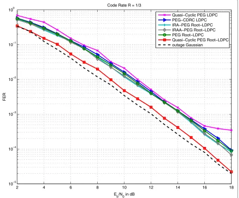
In Fig. 5, we compare the FER performance between the proposed PEG-CDRC LDPC, QC-PEG-root-LDPC, IRA PEG root-LDPC code, IRAA PEG root-LDPC codes, QC-PEG LDPC codes and QC-PEG-root-LDPC code, all forR= 13. From the results, it can be seen that the best performance is achieved by the proposed quasi-cyclic PEG root-LDPC code. IRA-PEG root-LDPC and IRAA-PEG root-LDPC have in average the same performance in terms of FER. The PEG-CDRC LDPC code is performing marginally worse than IRA and IRAA PEG root-check based LDPC codes. It was required to sacrifice the FER performance of the proposed PEG-CDRC LDPC codes to guarantee the full diversity of the parity check bits. Moreover, note that the proposed CDRC-LDPC code outperforms the QC-PEG LDPC code consistently across the range of FER con-sidered, with an improvement of 2 dB below a FER of 10−3.
10 12 14 16 18 20 22 24 26
10−4 10−3 10−2 10−1 100
Eb/N0 in dB
FER
Code Rate R = 1/2
PEG LDPC
Random Root−LDPC PEG−CDRC LDPC IRA−PEG Root−LDPC IRAA−PEG Root−LDPC PEG−Root−LDPC
Quasi−Cyclic PEG Root−LDPC outage Gaussian
2 4 6 8 10 12 14 16 18 10−5
10−4 10−3 10−2 10−1 100
E
b/N0 in dB
FER
Code Rate R = 1/3
Quasi−Cyclic PEG LDPC PEG−CDRC LDPC IRA−PEG Root−LDPC IRAA−PEG Root−LDPC PEG Root−LDPC
Quasi−Cyclic PEG Root−LDPC outage Gaussian
Fig. 5FER performanceF=3. FER performance for the CDRC-LDPC, QC-PEG-root-LDPC , IRA-PEG root-LDPC, IRAA-PEG root-LDPC and QC-PEG LDPC codes over a block-fading channel withF=3 andN=900 bits. The maximum number of iterations is 20
The proposed QC-PEG-root-LDPC code outperforms the QC-PEG LDPC code by about 3.5 dB, also between a FER of 10−3and 10−4.
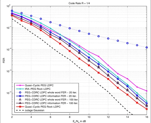
In Fig. 6, we compared the FER performance between the proposed PEG-CDRC LDPC, QC-PEG-root-LDPC codes, IRA-PEG-root-LDPC and QC-PEG LDPC codes all for R = 14. The codeword length isN = 1024 bits. From the results, it can be noted that the proposed PEG-CDRC LDPC code outperforms the QC-PEG LDPC code by about 1.5 dB while the proposed QC-PEG-root-LDPC code outperforms the QC-PEG QC-PEG-root-LDPC code by about 2.5 dB. In addition, note that only the PEG-based root-LDPC codes are able to achieve the full-diversity order of the channel. For the PEG-CDRC LDPC code, the FER of the whole code word is also included at both
2 4 6 8 10 12 14 16 10−4
10−3 10−2 10−1 100
E
b/N0 in dB
FER
Code Rate R = 1/4
Quasi−Cyclic PEG LDPC IRA−PEG Root−LDPC
PEG−CDRC LDPC whole word FER − 20 iter. PEG−CDRC LDPC information FER − 20 iter. PEG−CDRC LDPC whole word FER − 100 iter. PEG−CDRC LDPC information FER − 100 iter. Quasi−Cyclic PEG Root−LDPC
outage Gaussian
Fig. 6FER performanceF=4. FER performance for the PEG-CDRC LDPC, QC-PEG-root-LDPC and QC-PEG LDPC codes over a block-fading channel withF=4 andN=1024 bits. The maximum number of iterations is 20
structures found in the graphs of those codes, which offer a reduction in encoding complexity and diversity-achieving performance at the expense of reduced coding gain.
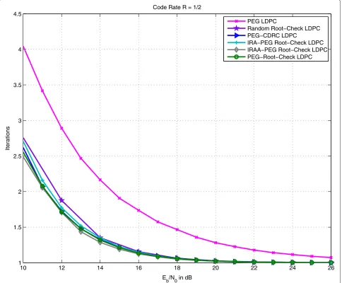
Figure 7 shows the average number of iterations re-quired by the proposed PEG-CDRC LDPC codes, IRA PEG root-LDPC code, IRAA PEG root-LDPC codes, PEG-root-LDPC, random root-LDPC and PEG-based LDPC [25] codes, all forR = 12. The decoder was operated to a maximum of 5 iterations and with the zero syndrome stopping criterion in place. For the entire SNR region, in average, we can observe that the proposed PEG root-check-based LDPC codes require less decoding iterations than standard PEG LDPC code. It must be mentioned that for medium to high SNR the average required number of iterations is less than 2 iterations. The average number
of iterations, less than 2 at medium to high SNR, corrob-orates with hardware friendly capabilities of structured LDPC codes [8].
7 Conclusion
10 12 14 16 18 20 22 24 26 1
1.5 2 2.5 3 3.5 4 4.5
E
b/N0 in dB
Iterations
Code Rate R = 1/2
PEG LDPC
Random Root−Check LDPC PEG−CDRC LDPC
IRA−PEG Root−Check LDPC IRAA−PEG Root−Check LDPC PEG−Root−Check LDPC
Fig. 7Iterations performance comparison forF=2. Average number of required iterations for the proposed PEG-CDRC LDPC codes, IRA PEG root-LDPC code, IRAA PEG root-LDPC codes, PEG-root-LDPC, random root-LDPC and PEG-based LDPC codes with codeword lengthN=1024 bits over a block-fading channel withF=2. Maximum number of iterations 5
PEG-CDRC LDPC codes are RA-based LDPC codes which are simple to encode and the parity-check matrix can be easily designed.
Competing interests
The authors declare that they have no competing interests.
Acknowledgements
This work was partially supported by PNPD/CAPES and CNPq (Brazil), under grant 237676/2012-5.
Received: 6 April 2015 Accepted: 28 August 2015
References
1. IEEE-WLAN 802.11ad,Very high throughput 60 GHz. (IEEE, New York, 2012). http://standards.ieee.org/getieee802/download/802.11ad-2012.pdf. Accessed 15 Sept 2015
2. RG Gallager, Low-density parity-check codes. IRE Trans. Inform. Theory.
20, 21–28 (1962)
3. M Luby, M Mitzenmacher, A Shokrollahi, D Spielman, V Stemann, in Proceedings of the Twenty-Ninth Annual ACM Symposium on Theory of Computing. Practical loss-resilient codes (El Paso, TX, USA, 4–6 May 1997) 4. E Biglieri, J Proakis, S Shamai, Fading channels: information-theoretic and communications aspects. IEEE Trans. Inform. Theory.44(6), 2619–92 (1998) 5. TS Rappaport,Wireless Communications Principles and Practice, 1st edn.
(Prentice-Hall, New Jersey, 1999)
6. LH Ozarow, S Shamai, AD Wyner, Information theoretic considerations for cellular mobile radio. IEEE Trans. Veh. Technol.43(2), 359–78 (1994) 7. JJ Boutros, A Guillen i Fabregas, E Biglieri, G Zemor, Low-density
parity-check codes for nonergodic block-fading channels. IEEE Trans. Inform. Theory.56(9), 4286–300 (2010)
8. Y Li, M Salehi, inProceedings of the 44th Annual Conference on Information Sciences and Systems (CISS). Quasi-cyclic LDPC code design for block-fading channels (Princeton University USA, 17–19 March 2010) 9. MP Fossorier, Quasi-cyclic low-density parity-check codes from circulant
10. AGD Uchôa, C Healy, RC de Lamare, RD Souza, Design of LDPC codes based on progressive edge growth techniques for block fading channels. IEEE Comms. Lett.15, 1221–3 (2011)
11. D Duyck, JJ Boutros, M Moeneclaey, inProceedings of the 18th IEEE Symposium on Communications and Vehicular Technology in the Benelux. Full diversity random LDPC codes (Ghent, Belgium, 22–23 November 2011)
12. CT Healy, RC de Lamare, inProceedings of the Tenth International Symposium On Wireless Communication Systems. Full diversity LDPC codes with a reduced structure for general block fading channels (Ilmenau, Germany, 27–30 August 2013)
13. AGD Uchoa, CT Healy, RC de Lamare, Iterative detection and decoding algorithms for MIMO systems in block-fading channels using LDPC codes. IEEE Trans. Veh. Technol (2015). doi:10.1109/TVT.2015.2432099
14. AGD Uchôa, C Healy, RC de Lamare, RD Souza, inProceedings of the 9th IEEE International Symposium on Wireless Communication Systems. Generalised Quasi-Cyclic LDPC codes based on progressive edge growth techniques for block fading channels (Paris, France, 28–31 August 2012) 15. Uchôa, AGD, C Healy, RC de Lamare, inProceedings of the Tenth
International Symposium On Wireless Communication Systems. Repeat accumulate based constructions for LDPC codes on fading channels (Ilmenau, Germany, 27–30 August 2013)
16. JJ Boutros,Controlled doping via high-order rootchecks in graph codes. (Paper presented at IEEE Communication Theory Workshop, Sitges, Catalonia, Spain, 2011). Available online from http://www.josephboutros. org/coding/rootLDPCdoping.pdf
17. X Wang, HV Poor, Iterative (turbo) soft interference cancellation and decoding for coded CDMA. IEEE Trans. Commun.47(7), 1046–61 (1999) 18. RC de Lamare, R Sampaio-Neto, Minimum mean-squared error iterative successive parallel arbitrated decision feedback detectors for DS-CDMA systems. IEEE Trans. Commun.56(5), 778–89 (2008)
19. GD Golden, CJ Foschini, RA Valenzuela, PW Wolniansky, Detection algorithm and initial laboratory results using v-blast space-time communication architecture. Electron. Lett.35, 14–16 (1999)
20. R Fa, RC de Lamare, Multi-branch successive interference cancellation for MIMO spatial multiplexing systems: design, analysis and adaptive implementation. IET Commun.5, 484–94 (2011)
21. RC de Lamare, Adaptive and iterative multi-branch MMSE decision feedback detection algorithms for multi-antenna systems. IEEE Trans. Wireless Commun.12(10), 5294–308 (2013)
22. T Richardson, R Urbanke, The capacity of low density parity check codes under message passing decoding. IEEE Trans. Inform. Theory.47, 599–618 (2001) 23. Z Li, BVKV Kumar, inIEEE ASILOMARSSC’04. A class of good quasi-cyclic
low-density parity check codes based on progressive edge growth graph, (2004), pp. 1990–1994
24. A Guillen i Fabregas, G Caire, Coded modulation in the block-fading channel: coding theorems and code construction. IEEE Trans. Inform. Theory.52(1), 91–114 (2006)
25. X-Y Hu, E Eleftheriou, DM Arnold, Regular and irregular progressive edge-growth tanner graphs. IEEE Trans. Inform. Theory.51(1), 386–98 (2005)
26. AKH Jin, R McEliece, inProceedings of the 2nd International Symposium on Turbo Codes and Related Topics. Irregular repeat-accumulate codes (Brest, France, September 2000)
27. WE Ryan, S Lin,Channel Codes Classical and Modern. (Cambridge University Press, Cambridge, UK, 2009)
28. AGD Uchôa, C Healy, RC de Lamare, RD Souza, inProceedings of the Eighth International Symposium On Wireless Communication Systems. LDPC codes based on progressive edge growth techniques for block fading channels (Aachen, Germany, 6–9 November 2011)
29. S Johnson, S Weller, inProceedings of the 6th Australian Communications Theory Workshop. Interleaver and Accumulator Design for Systematic Repeat-Accumulate Codes (Brisbane, Australia, 2–4 Feb 2005) 30. JJ Boutros, inInformation Theory and Applications Workshop, 2009.
Diversity and coding gain evolution in graph codes, (2009), pp. 34–43 31. AGD Uchôa, C Healy, RC de Lamare, P Li, inProceedings of the IEEE Wireless
Communications and Networking Conference (WCNC). Iterative detection and decoding algorithms for block-fading channels using LDPC codes (Istanbul, Turkey, 6–9 April 2014)
Submit your manuscript to a
journal and benefi t from:
7Convenient online submission 7Rigorous peer review
7Immediate publication on acceptance 7Open access: articles freely available online 7High visibility within the fi eld
7Retaining the copyright to your article