Thesis by
Edgard Schweig
In Partial Fulfillment of the Requirements
for the Degree of
Doctor of Philosophy
California Institute of Technology
Pasadena, California
1982
ACKNOWLEDGEMENTS
It gives me pleasure to thank Dr. William B. Bridges for his
valuable assistance in the course of this work. I am also indebted to
Dr. Thomas C. McGill for providing me with the opportunity of doing an
interesting experimental project and many encouragements.
As well, I would like to thank my friends at Caltech for their
help and support: without them, this thesis would not have been! I am
particularly indebted to Luc Heymans, Augusto Sagnotti (and his wife
Francesca) and Barton Zwiebach (and his wife Gaby). The students and
research fellows of "McGroup", i.e. TCM's group, have provided me with
a congenial environment that broke the monotony of work.
Mr. and Mrs. J. Mahieu, in Brussels, and, Mr. and Mrs.
0. Zwiebach, in Lima, have given me their kind affection.
I have enjoyed collaborating on various experiments with Dr.
Marvin B. Klein, at the Hughes Aircraft Research Laboratories.
Last,not least, I would like to thank very much Mrs. Vere Snell
for her excellent secretarial help.
Financial support has been provided by the Office of Naval
In this thesis, we analyze high-permittivity dielectric waveguides
for use as guiding structures of millimeter waves, Two basic geometries
are considered: the circular and rectangular guides.
In Part I, we describe the theory of round fibers surrounded by an
infinite cladding. Millimeter wavelengths are comparable to the
physi-cal dimensions of the guide, Therefore, a large difference in
permitti-vity between the core and the cladding is required in order to provide
for a tight confinement of the fields, We present the results of
com-putations of the propagation characteristics and losses of fibers of
very high permittivity, We note that the distribution of the
electro-magnetic power between the core and the cladding can be deduced from
the dispersion curves. Finally, we consider the feasibility of a
di-electric fiber made of thallium bromide-iodide (KRS-5) for the long
distance transmission of W-band signals (94 GHz). Using our
measure-ments of the dielectric parameters of KRS-5, we find that the losses
are several orders of magnitude higher than the losses of conventional
metallic waveguides.
In Part II, we analyze rectangular dielectric guides made of
high-permittivity materials such as GaAs that would permit the fabrication
of active devices directly into the transmission line, We present a new
numerical technique base on finite-differences for computing the modes
modes of a rectangular dielectric waveguide and compare the numerical
results to those obtained from Marcatili's closed-form solution. We
find that this latter one is a good approximation for the dominant mode
of a rectangular guide even when the permittivity of the guide is large
compared to the outer medium, For higher order modes, Marcatili's
solution predicts incorrect propagation curves. We have also observed
the presence in our numerical solution of "spurious modes" that are
thought to be due to the mathematical indefinitiveness of the problem,
In Part III, we present a waveguide technique for the measurement
of complex dielectric constants at millimiter wave frequencies: the
shorted-waveguide method. Waveguide methods have been extensively used
at lower frequencies but this is the first application at 94 GHZ. We
use a novel sample preparation technique that allows for an accurate and
gap-free positionment of a ductile dielectric material inside a metallic
waveguide, We note that the correct choice of sample lengths is
critical to the accuracy of the measurement of the loss tangent.
Finally, we stm1marize the results of our measurement of the dielectric
constant and loss tangent of thallium bromide-iodide (KRS.,-5) and
Parts of this thesis have been or will be published under the following
titles:
Part II:
Part III:
"Computer Analysis of Dielectric Waveguides for Millimeter
Waves", Edgard Schweig and William B. Bridges,
(to be submitted: IEEE Trans. MTT).
"Computer Analysis of Rectangular Dielectric Waveguides for
Millimeter Waves", Edgard Schweig and William B. Bridges,
IEEE International Conference on Inf rared and Millimeter
Waves, Miami, December 1982.
"Measurement of the Dielectric Constant and Loss Tangent of Thallium Mixed Halide Crystals KRS-5 and KRS-6 at 95 GHz",
William B. Bridges, Marvin B. Klein and Edgard Schweig, IEEE
Trans. Microwave Th. Tech., Vol. MTT-30, March 1982, pp.
ABSTRACT
PART I: Round Dielectric Fibers
1. Introduction
2. Guided Modes for Unlimited Cladding
2.1 Assumptions
2.2 Field Solutions
2.3 Power Distribution
3. Numerical Results
4.
Linearly-Polarized Modes5. Guided Mode Attenuation
6. Attempt at a Practical Design
7. Conclusions Bibliography
PART II: Rectangular Dielectric Waveguides
1. Introduction
2. Marcatili's solution
2.1 Assumptions
2.2 Derivation and Properties
2.3 Derivation and Properties
2.4 Characteristic Equations:
3. Review of Solutions
3.1 Effective Index
3.2 Mode-Matching
3.3 Finite- Elements
4. Finite-Differences
4.1 Introduction
4. 2 Self- Adjoint Operators
of the Ex -Modes
of the Eyq_Modes pq
Closed-form Solutions
i i i
4.3 Variational Principle for Guided Modes 66
4.4 FD: Variational Approach 70
4.5 Properties of FD Approximations 77
4.6 Solution of the Matrix Eigenvalue Problem 82
4.7 Mode Designation 84
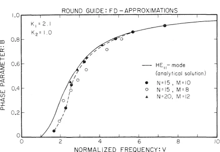
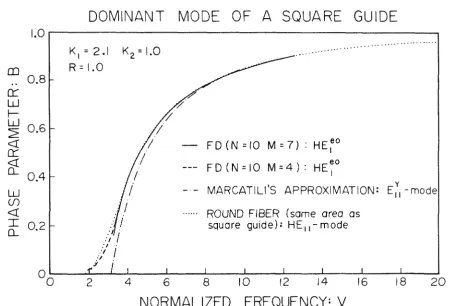
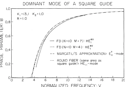
4.8 Numerical Results and Comparison with Other Work 84
4.8.1 Round Guide 86
4.8.2 Marcatili's Approximation of a Square Guide:
4.8.3 4.8.4
4.8.5
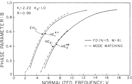
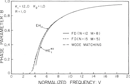
Discussion Mode Matching
Dispersion Curves for K
1=2.l and K1=13.l Higher Order Modes
Field Plots 4.9 Spurious Modes
5. Conclusions Bibliography
PART III: Measurement of Complex Permittivity at Millimeter Wave Frequency
1. Introduction
2. Survey of Available Experimental Methods
2.1 Quasi-Optical Techniques 2.1.l Free-Space Path 2.1.2 Open Resonator
2.2 Cavity
3. Waveguide Techniques 3.1 Shorted Waveguide
3.1.1 Mathematical Formulation
3.1.2 Optimum Sample Length 3.1.3 Air Gaps
3.1.4 Waveguide Wall Losses 3.2 Results of Measurements
Bibliography 146
APPENDIX A: Waveguide Modes: Longitudinal Field Formulation 149
Bibliography
APPENDIX B: FD-Matrices
APPENDIX C: Wave-Equation Approach to Finite-Differences
1. Introduction
2. Wave-Equation Approach
3. Numerical Results
Bibliography
151
152
158
158
158
164
1. Introduction
1 2 3
Hondros and Debye and, more recently, Elsasser and Chandler
have studied a dielectric rod as a structure capable of supporting a
"surface wave" that is, an electromagnetic wave which is bound to the
surface of the structure: The fields are characterized by an exponential
decay away from the surface and a propagation function exp (-jSz). These
studies have shown some of the peculiar features of the "surface wave"
modes that differ from the modes existing in conventional metallic
wave-guides:
a) the existence of a guided mode with no low-frequency
cutoff;
b) a finite spectrum of discrete guided modes together
with a continuous spectrum of radiation modes;
c) the possibility of modes that propagate with a phase
velocity less than that of light.
Since the late 1960's, optical waveguides, mostly in the form of
glass fibers, have been studied extensively for their applications in
optical communication systems (see, for example, the review paper by
Gloge, Ref. 4). Such optical waveguides consist of a core surrounded
by a cladding with an index of refraction that is somewhat lower than
the index of the core (see Fig.
1).
The difference in index is, in*
practice, of the order of only a few parts in a thousand , which leads
that can propagate. The results can be summarized in the form of
curves that are independent of the actual difference in refractive
index as long as it is a small quantity. Typical fiber core diameters
are about 10 µm which is much larger than the wavelength of the light
that propagates on the fiber (A 0 < 1 µm).
~
In contrast, millimeter-wavelengths are comparable to the
physical dimensions of the guiding structures, and it is thus
necessary to provide for a tighter confinement of the fields within the
guide ("strongly-guiding fiber"). This is achieved by using
materials that present a large difference of refractive index between
the core and the cladding. In such a guide, it is necessary to compute
the exact solutions to Maxwell's equations for each configuration.
Relatively little work has appeared in the recent literature on such
strongly-guiding structures, compared to the vast literature on
weakly-guiding optical fibers.
We will describe in the next sections the theory of circular
fibers and the results of some computations of the propagation
charac-*
teristics and losses of fibers of very high refractive index.We will also compare these results with the approximations employed for
the study of weakly-guiding fibers.
2.1. Assumptions
The fibers which we would use for signal transmission are
designed in such a way that the fiber modes are guided by the core: the
fields and their energy are well confined inside or near the
core. The evanescent fields near the outer cladding boundary should
be so small that the external jacket will not affect the core modes.
Therefore, we need, in practice, to extend the cladding to a large
enough diameter for the intensity of the evanescent fields to decay to
a very low value (compatible with the losses that can be tolerated in
the fiber).
In our theoretical model, we will let the cladding region extend
to infinity. This will not change any of the dominant mode
characteris-tics, except for the very small attenuation due to jacket absorption.
Also, we will assume that all media are isotropic, homogeneous and
lossless. The losses will be introduced afterwards as a perturbation.
2.2. Field Solutions
The fiber has a core of index n
1 and radius a and is surrounded
by an infinite cladding of index n
2 (Fig. 2). We will consider a
time-harmonic solution of frequency
w
and a cylindrical system of coordinates(r,¢,z) with the z-axis along the fiber axis. We adopt the longitudinal
components, E and H , as the generating components of the
electro-z z
must be:
exp (-j Bz)
The longitudinal fields must therefore satisfy the following transverse
wave equation:
(''iJ2
+
k2 ) {Ez}= 0
t r H
q
zwhere V2 is the transverse Laplacian operator t
(1)
(2)
The separation constant k depends on the region considered, i.e., rq
k2
=
n2 k2 - B2r q o
q
for q :::: 1,2 (3)
where k is the free-space wavenumber. The transversal field distri-o
*
bution can be written as
in region 1:
E
AE
J (k r) cos mcpzl m r 1 (5. a)
H =
~
J (k r) sin mcp for r < a,zl m rl - (5.b)
E
=
BE K (jk r) sin m¢ (6. a)z2 m r2
H
=
BH K (jk r) cos m¢ for r > a. (6.b)z2 m r2
The choice of radial functional dependence given in Eqs. 5 and
6 assures, for a core mode, the proper behavior of the fields.
-+ -+
The tangential components of the fields E and H must be matched
at the interface r=a. The matching conditions specify a system of
four linear homogeneous equations for the four undetermined quantities
~- BH. The compatibility condition of the system is the characteristic
equation that yields the values of
S
corresponding to modes ofpropaga-tion.
The various modes are designated E , H , HE , EH . The first
on on mn mn
capital letter shows the dominant field component; the second letter
(if any) indicates that the mode is hybrid, i.e., that it has both
longitudinal electric and magnetic fields. The subscripts correspond
to the order of the mode: m for the angular variation and n for the
radial variation.
To describe the solutions, we will use the following abbreviations
that are common in the description of optical fibers (see, for example,
Ref. S). We define a radial phase parameter in the core, u, and a
jk a
=
a~B
2 k2 2v = n2
r2 0 (8)
These quantities are real and positive for propagating modes. We also
define a normalized frequency, V, (also called fiber parameter):
(9)
and a normalized phase parameter, B:
B (IO)
This last parameter is very useful in the description of dispersion
characteristics as it is normalized to the range [O,l].
*
and
*
The effective index for the mode in consideration is given by
N = B/k
0 (11)
Finally, we will use the following combinations of Bessel functions:
J' (u) y
=
mu J (u) m
m
(12)
K' (v)
x
= mv K (v) m
m
(13)
(14)
The mathematical properties of Eq. 14 allow us to deduce some of
the properties of the modes without actually solving it.
Let us consider first the case of the axially symmetric modes:
m
=
0. These modes are either transverse magnetic or transverse electric.The characteristic equation splits into:
y
+
x=
00 0 for the H-modes
for the E-modes
When m
#
0 the fields have an angular dependence~ the characteristicequation can be thought of as a quadratic equation in terms of Y and m
rewritten as,
y =
-m
x
m (17)The upper sign corresponds to the HE-modes while the lower corresponds
to the EH-modes. The HE
11 and EH11 modes are the lowest hybrid ones. The HE
11-modes resembles, inside the core, the H11-mode of a round
metallic guide in the field distribution. Unlike the HE
11.-metallic
*
pipe mode, this particular solution to Eq. 17 has a zero cutoff and01 01 modes: They have a cutoff at V = 2.405. At very low frequency
(V ~ 2.405), the behavior of the HE
11-mode can be approximated by 5
B = -1.26 J [l 2/ 2)]/ 2[ 2- exp
l-
+n1 n 2 V J.v
(18)The limiting forms of the characteristic equations are summarized
in Table I. We note that for all modes with m=O and m=l, the HE 11 excepted, the cutoff frequency is a particular root of the Bessel
func-tion J (u), where m corresponds to the circumferential order. The m
cutoff frequency is then independent of the index ratio n
1/n2• Far from cutoff, i.e., for large values of V, all modes have a
behavior of the form 5
(19)
where u is a Bessel root, as indicated in Table I. 00
2.3 Power Distribution
An important consideration in the design of a clad dielectric fiber is the distribution of power between the core and the cladding.
The fraction of power that flows in the core will determine, to first
approximation (see Section 5), the attenuation due to dielectric
Circumferential
order
m = 0
1
> 2
HE
-modesrrrp
at cut-off
J
0(u)
=
o
J
1 (u)
=
0Jm-2(u)
=
-Jm-1 (u)
(EOp for m = O)
far above
J
1(u) = 0 J
0(u) =
o
2 2
nl-n2
J
1 (u)
=
02 2
m-nl+n2
EH
-modesrrrp
at cut-off
J
0 (u)
=
o
J
1 (u)
=
0(Hop for m = 0) far above
J
1(u) = 0 J
2(u)
=
0(excluding u=O)
J (u)
=
0m Jm+l (u)
=
0I-' I-'
"Cut-off" and "far above cut-off" correspond to the following limits of the radial attenuation parameter v:
cut-off: v
=
0far above: v + oo
The radial phase parameter, u, and the radial attenuation parameter, v, are related to the normalized
fre-2 2 2
*
vector, then the total power traveling along the guide is given by:
pt =
f
sz dx dy (20)CXJ
The fractions of the total power propagating respectively in the
core and in the cladding (assumed to be of infinite extent) are
obtained from
p
J
s
dx dy corez (2la)
core
p
(
s
dx dyclad
J
z (2lb)clad
The fractions that we will consider are:
Peare p core t /P (22a)
and
pclad/Pt (22b)
with
p core
+
P clad = IIf the waveguide incorporates only isotropic and non-dispersive
(~~
=
0) media which may be inhomogeneous in the transverse direction, 6we can use the following identity
c - - = (23) v v
dw2
I
00g p
s
dx dyz
where v and v are respectively the group and phase velocities,
g p
Eq. (23) is rigorous and can be derived either by expressing
+ + +
the Poynting vector S in terms of the fields E and H and integrating over the cross section 7 or by applying a perturbation 6w to the wave
+ + 8
equations for E and H. By introducing the normalized parameters
V and B (see Eqs. 9 and 10) in the left-hand side of Eq. (23) we
obtain:
2 dB
B
1( 2 2) [d(V B) 2c
dw w
=
2
nl - n2 d V+
B]+
n2For a step-index fiber, the right-hand side simplifies into
J
00n2
s
z dx dy 2 2= nl pcore
+
n2 pcladf
00sz dx dyHence, the fraction of power in the core can be obtained very simply
from the propagation characteristic, i.e., the curve B(V),
by using the following relation:
nor the use of Eq. (23) require the assumption of a weakly guiding
fiber.
3. Numerical Results
A program was written to solve numerically the characteristic
equation for a round fiber with an infinite cladding. The results are
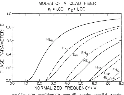
presented in Figs, 3-5 in terms of the normalized parameters V and B.
*
Fig. 3 corresponds to a Teflon core surrounded by air and Figs. 4
and 5 correspond to a core of KRS-5 surrounded by air and Teflon,
respectively.
The sequence of the various modes, that is, the order in which
they turn on as the normalized frequency is increased, remains the same
in all three cases. But as the index of the core is increased, the
phase parameter of the HEpq- and E
0q-modes remains very small until a higher value of V is reached. This tendency is lessened when the index of the cladding is increased, i.e., the important factor is the ratio
of refractive indices between the core and the cladding. The H
0q-modes
are independent of the index ratio while the behavior of the EH -modes pq
depends less on the index ratio than the HE -modes. pq
For most millimeter-wave applications, the waveguide would be
used in a single-mode configuration. It is therefore important to
en
0::::
w
r-w
~ <( 0::::
<!
()_
w
(j)
<t:
I ()_
1.0
0.8
0.6
0.4
0.2
0.0
MODES OF A CLAD FIBER
n
1
=1.60
n
2
=
1.00
0.0
1.0
2.0
3.0
4.0
5.0
6.0
7.0
8.0
NORMALIZED FREQUENCY: V
---:E-modes --:H-modes
-:HE
1 ,p-modes ···=EH
1 ,p-modes
Figure 3. Dispersion curves for the modes of a round fiber with infinite cladding:
core : n
1 = 1.60 (Teflon) cladding: n
MODES OF A CLAD FIBER
n
1=5.67
n2
=
1.00
1.0...---.----,----,----.--.---,----r-~
0::
w
I-0.8
~
0.6
4
0::
4
0...
0.4
w
Cf)4
I
0.2
0..... ..
..
···
..
...
...
---:E-
modes --:H-modes --:HE1,p-modes···:EH
1,p-modesFigure 4. Dispersion curves for the modes of a round fiber with infinite cladding. The higher index core modifies the way the modes go to cutoff. The cutoff frequencies are independent of the index ratio n
1/n2• core : n1 = 5.67 (KRS-5)
Cl)
0:::
w
f-w
~
<(
0:::
<! CL
w
(/)
<(
I CL
1.0
0.8
0.6
0.4
0.2
0.0
MODES OF A CLAD FIBER
n
1
=
5 .6 7
n
2
=
I.
6 0
...
...
··
0.0
1.0
2.0
3.0
4.0
5.0
6.0
7.0
8.0
NORMALIZED FREQUENCY: V
---: E- modes - -: H-modes -:HE
1 ,p -modes ···:EH
1 -,pmodes
Figure 5. Dispersion curves for the modes of a round fiber with infinite cladding. The presence of a Teflon cladding lowers the index ratio compared to the case illustrated in Fig. 4:
core : n
1 = 5,67 (KRS-5) cladding: n
mode can exist. This is similar to the useful frequency range of
ordinary metallic "dominant-mode waveguide". However, unlike the
dominant mode in a metallic guide, the HE
11-mode has no
low-frequency cutoff. As the normalized frequency is decreased, more
and more of the power will flow outside of the core, resulting in weak
guiding or "loose confinement". We will consider the HE
11-mode to
be strongly guided, or "closely confined", when at least 90% of the
power is propagating within the core, This constitutes, of course,
an arbitrary definition of the lower frequency limit of the
single-mode range of operation, The high-frequency limit will occur when the
next mode is turned on, which corresponds to a fixed value of V=2.405,
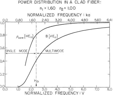
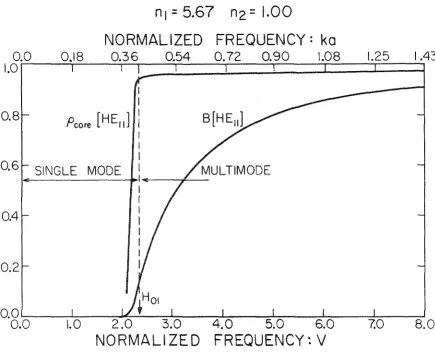
independent of the ratio of refractive indices. Fig. 6-9 show the
dispersion characteristic and power distribution in the different
core/cladding combinations considered above. If the core has a high
refractive index, the HE
11-mode will turn on very rapidly, as seen by comparing Figs, 6 and 7. Figs, 8 and 9 show the turn on of this
mode on an expanded scale in the case of a high-index core
surrounded by claddings of different indices, It can be noted that a
reduction of index step between the core and the cladding will slow
the rise in the fraction of power carried by the core to the point
that for a KRS-5/Teflon fiber, the next mode appears before strong
guidance of the HE
11-mode is attained (following our definition of
POWER DISTRIBUTION IN A CLAD FIBER:
n
1 =
1.60
n
2 =
1.00
NORMALIZED FREQUENCY: ko
0.0
0.80
1.60
2.40
3.20
4.00
4.80
5.60
6.41
1.01--r---r~--i--~======~====i======r==i
0.8
0.6
SINGLE
0.4
0.2
Ho1
t
o.o.__ ___ ::.,__ _
_ J _ _ _ __.__ _ _ J _ _ _ _ _ l _ _ _ ~ _ _ __J_ _ _ _ _ . J0.0
1.0
2.0
3.0
4.0
5.0
6.0
7.0
NORMALIZED FREQUENCY: V
Figure 6. Dispersion characteristic and power distribution of a round
fiber with infinite cladding. A single mode operation is desirable in
most applications.
0.0
1.0
POWER DISTRIBUTION IN A CLAD FIBER:
n1
=
5.67
n2
=
1.00
NORMALIZED FREQUENCY: ka
0.18
0.36
0.54
0.72
0.90
1.08
1.25
o.
5 SINGLE MODE0.4
0.2
1.43
tH01
Q0.__~~...._~~---~~--~~_._~~----~~~...._~~~~~-0.0
1.0
2.0
3.0
4.0
5.0
6.0
7.0
NORMALIZED FREQUENCY: V
Figure 7. Dispersion characteristics and power distribution of a round
fiber with infinite cladding. The high-index core introduces a very
sharp rise in the power distribution as the mode is turned on.
POWER DISTRIBUTION IN A CLAD FIBER:
n
1
=
5.67
n
2
=
1.00
1.0.---.---.----.---r----,---r---,---==::i
0.8
0.6
0.4
0.2
90°/o _ _ _ _
STRONGLY GUIDE HE 11
SINGLE MULTIMODE
10 °/o
Figure 8. Enlarged view of the turn on of the HE
11-mode represented
90%
0.8
0.6
0.4
0.2
10%
POWER DISTRIBUTION IN A CLAD FIBER:
n1
=5.67
n2
= 1.60
I STRONGLY GUIDED
HE
11,_
I
SINGLE MODE !MULTIMODE
1 -
,I
I
+
-0.0L-~____L~~-1~~_.J_---=:::::::::L~~_J_~~..L_~~1-.~__J
2.00
2.13
2.25
2.38
2.50
2.63
2.75
2.88
3.00
NORMALIZED FREQUENCY: V
close as possible to unity.
The very steep slope of the dominant HE
11-dispersion curve in a
high-index fiber can be explained by considering Eq. 18, which describes the behavior of this mode for V ~ 1:
(18)
Using Eq. 24, we find that the power distribution is approximately
given by
(25a)
for the HE
11-mode and V ~ l; this relation can also be written as:
p /B
core (25b)
Equations (25) indicate that for a large ratio n
1/n2, p core will rise
much faster than B, as the mode is turned on, This phenomenon is
actually an artifact due to the particular normalization that we
Consider the cylindrical fiber consisting of a core of index
n
1 surrounded by a cladding of index n2 and infinite extent (Fig. 2).
In
the case of a weakly-guiding fiber, the refractive indices satisfy6.
=
<< l (26)In this case, we can construct modes whose transverse fields are
mostly polarized in one direction: the ''linearly.--polarized modes" 4•5 We postulate the following transverse field distribution in the core
E 1
E = H - - = 0 E.Q, JR, (ur /a) cos 9,cp
y x µo nl (27a)
and, in the cladding
E
1
"
E = H - - = 0 E.Q, K.Q, (vr/a) cos £¢
y x µo n2 (27b)
where u and v are the transverse parameters that were defined previously
(Eqs. 7 and 8). The longitudinal components are obtained by using the Maxwell curl equations. One finds that
z
0Ez = j k
0
H z
• (lE = _] _ _ L
k
z
dx 0 0to the transverse ones; the factors involved are u/(ka) and v/(ka)
k
which because of the definition of u and v are of order 62
• We will
therefore neglect these components when matching the tangential fields
at the interface r=a. To first order in~. we then obtain the following
characteristic equation
u J£-l (u)
J (u) -v
K,Q,_J (v)
K (v) (29)
5
for the linearly polarized (LP) modes. These modes can be shown to be particular superpositions of the HE- and EH- fiber modes. For a
small index difference, 6 << 1, the HE£+l -mode is nearly degenerate
,p
The with the EH2_
1,P-mode and together, they form the LP2P-mode.
LP
0P-modes represent a special case because they correspond to the
HE1P-modes that are already linearly polarized (only when /1 << 1).
For the dominant LP
01-mode, we can obtain the characteristic
equation in closed form, to the same degree of approximation;
u(V) (28)
where u
01 = 2.405 represents the first zero of the Bessel function
J
0(u). To obtain the characteristic equation in the form B(V), we
B
=
1 - (u/V)The power distribution of this mode is given by
2 Ko(v)
p core = 1 - (u/V) [l - K 1 (v)
(29)
We have compared, in Fig. 10, the dispersion characteristic for
the dominant mode of a round fiber, as obtained by using respectively:
- the LP
01-mode closed-form characteristic equation; the exact HE
11-mode for n1 1.500 and n2 the exact HE
11-mode for n1
=
5,667 and n21.000
1.000.
We observe that, as the index of the core is increased to several
times the index of the outer medium, the LP
01-approximation diverges more and more from the exact solution, The same conclusion is
illus-trated, in an even more drastic manner, by Fig. 11 that compares the
power distributions, p • as computed from the same set of modes. core
5. Guided Mode Attenuation
Core and cladding materials were assumed, in what preceded, to
be lossless. In reality, guided modes lose power due to material
*
absorption and scattering at inhomogeneities, We will assume that
1.0
co
0.80:::
w
~
w
0.62
<{
0:::
~
0.4w
Cf)
<{ I 0.2
o_
0
···
/
/
LP01 -mode
I
He11-mode
I
I
n1=1.500 n2=1.0He
11-mode
:
n1 = 5.667 n
2= 1.0
:
:
0 2 4 6
NORMALIZED FREQUENCY:V
Figure 10. Comparison between the dispersion characteristics of the dominant fiber mode as computed by using the linearly-polarized mode approximation and the exact solution for a medium-index core (n
1=1,500) and a high-index core (n
1=5.667). The LP-approximation diverges at low frequencies.
···
I.
o
.---~-:-:-=... -:-:-:-
... -:-:-:-
... :-:-:
... -:--:-:
..
-~·.·::·
·=·: ·::·
·:~·. ·;::3·.·;3·. ·.:::;;;;· · m · ·.·;;;:::;· · ·:::====~...,I
---·--0...
'
o...-
0.8
..
z
0
1-::J 0.6 CD 0::: I--Cf) 0 0:::
w
~0
0... 0.4 0.2 I I I I I I iI
IL~
1
- modeHe11 -mode n1
=1.500
n2
=1.0
He11-mode
n1
=
5.667
n2=
1.0
01.--'~--&.~~~...i..~~~...,j..~~~.J..-~~~.1--~~--i.~~~-'-~~~~
0
2
NORMALIZED
4 6
FREQUENCY:V
Figure 11. Comparison between the power distribution for the dominant fiber and mode as computed by using the linearly-polarized mode approxi-mation and the exact solution for a medium index core (n
1=1.500) and a high index core (n
1=5.667). The LP-approximation is especially poor for a high index core.
very much shorter than a wavelength. Under these conditions, Rayleigh's
scattering law applies and the scattering loss can be accounted for
by an imaginary component of the complex refractive index:
for q=l,2 (20)
II
The absorption coefficient nq also includes the material absorption,
The guided mode will propagate with a complex propagation constant
y a
+
jS (21)where, for practical low-loss materials,
(22)
Due to the low absorption and scattering losses, the field distributions
of the guided modes are only slightly perturbed from the lossless case.
The attenuation a can therefore be computed by a perturbation method.
*
If only the core is lossy , we find that, disregarding signs, the
2 attenuation is given by
*
Without this assumption the righthand side of Eq, 23 will contain, in the numerator, an additional term, of the formI
bajEj 2
r dr1
a
=
dP t
=
2
!El
r dr(23) r dr
I
where S is the longitudinal component of the time-averaged Poynting z
vector and
a
is the conductivity of the material. This parameter isrelated to the loss tangent, tan
6,
and to the real part of the'
permittivity, E , by:
a
=
wE tano
Elsasser 2 introduces the dimensionless quantity R
(24)
(25)
For a plane wave propagating in an infinite medium of conductivity and
dielectric constant E, R has the value l/.;sr
value of R for the three lowest order modes:
for the m=l, HE
11-mode:
Y2+
l:_. - d__
l 2 4D-1 u u 2 2
-2- 1 1 +(N +Z)
v
- + -
2 2= u v
R
X
+ - -
4 NZ4
u
Elasser computed the
(26)
NX(D
+
z
2)+
NY(l+
z
2)+
2~(D+N
2)
- 2~(l+N
2)
x y2 2Y
1+1 1 1 + 2
- 4
u u
- x2
2X -1
1
y 1
1 2
- 4
v v
z
(The other quantities have been defined in Section 2,2.)
for m
=
0, the H01-mode
2Y + 1
y2 0
+ 2
0 1
R u N
y2 + 2Y + 1 0 x2 2X -1 0
0 2 0 2 (27)
u v
for m
o,
the E01-mode
y2 + -1
2Y -1 D-1 0 2
+ N2 (Y2 u
+
0 ) 2 ..!_ + ..!_ 0 2v
2 2 u
R = u v (28)
2Y +l
N(Y2 N(X2
2X -1
D
+
0)
-
+ 0 )0 2 0 2
lowest order modes and two different core indices, respectively,
1.500 and 5,667. As the frequency increases, all the curves exhibit
a maximum that is more pronounced for a higher core index. At high
frequency, the quantity R approaches the "plane-wave limit" 1/n 1.
We also plotted for reference the fraction of the total power that
propagates in the core, assuming that only the mode in consideration
is present. We see that the maximum in the curves corresponds to the
rise of the power fraction. The maximum indicates that at intermediate
frequencies, the attenuation can be several times the high-frequency
limit, which is equal to the attenuation that a plane wave propagating
in an infinite expanse of core material would encounter. This result may
be understood in simple physical terms. At very low frequencies most of
the fields are outside of the core and therefore are subject to little
attenuation. As the frequency is increased, the fields become more
con-centrated within the core. In a ray-optics picture, this situation
cor-responds to rays that bounce back and forth between the boundaries of the
guide. The path followed by a ray is thus actually longer than if it
were propagating along the guide axis and therefore the attenuation per
physical length of guide is higher. At high frequencies, the
guide radius becomes very large compared to a wavelength and the
mode can be thought of as a plane wave propagating parallel to
0::::
c
Q_
1.0
0.8
0.6
0.4
0.2
1.0
0.8
0.6
0.4
0.2
HE
11
HE, I
EOI
ATTENUATION
n
1
=
1.5
n
2=1.0
POWER
DISTRIBUTION
0'---~--J~~_...__..___._~~-'-~~---~~--~~...._~--0
2
3
4
5
6
7
8
NORMALIZED FREQUENCY: V
0::::
c
Q_
2.0
HE 11
1.0
0.8
0.6
HE11
0.4
0.2
Ea1
Hal
Ea1
ATTENUATION
n
1
=
5.667
n
2=
1.000
POWER
DISTRIBUTION
OOL-~..L-~..L...L.-:::::::l-~-l..~_...~~..__~...._~-8
2
3
4
5
6
7
NORMALIZED FREQUENCY
:v
6. Attempt at a Practical Design
We will now consider from an engineering standpoint the
feasibility of a dielectric fiber made of KRS-5 for long distance
transmission of millimeter wave power.
The most important parameter of such a transmission system is the
total loss per unit of length. The total propagation losses result
from the dielectric losses in the core and cladding and from bending
losses.
a
=
acore+
acladding+
abending (29)In this analysis, we are interested in orders of magnitude rather than
exact numbers. We will therefore consider that the dielectric losses
are obtained by multiplying the material losses
°11
E tano
r for small tano and q=l,2
by the fraction of the power propagating in region q:
(30)
(3la)
The exact study of bending losses requires. the analysis of the modes
that propagate on a curved waveguide, and the reflection and radiation
phenomena that occur at the transition between the straight and curved
portions of guide. Several authors have proposed formulas for
com-puting the bending losses. Neuman, et al 9 have shown that these
formulas can be reduced to a common expression:
1 1
a '.::'. -R exp
[-R 61T2
(R/"'A )
0
] ' (32)
where R is the radius of curvature, A is the wavelength in the outer
0
medium, and r is the extension of the field in this region. (The
0
fields outside the core behave like K
1 (r/r0 ) , which can be approximated
by an exponential decay exp(-r/r ).)
0
We may now compute the fiber losses for three cases of practical
interest, namely, those fiber designs that have an attenuation
corn-parable to metallic waveguides. We will assume that only the
dominant HE
11-mode propagates in these fibers with infinite cladding.
a. KRS-5/Air Waveguide, As a benchmark value, we
determine the radius a of the core that makes the dielectric losses
correspond to the losses of conventional metallic waveguides at
Cl
core 3 dB/m
=
3.45xl0-4 mm-lFor very small V, we can approximate the dispersion relation of the
HE
11-mode by 5
B
~
1
·
26 exp [-D/V2]v2 (33)
2
where D
=
1+
(n1/n2) . Also, we have seen earlier that the power distribution is given bypcore
and therefore,
B
+
y_
dB 2 dVp
~
1·26 D exp(-D/V2)core V4
Because a
=
pa._
this value of a corresponds tocore core M core
(24)
(34)
pcore 3.lxl0-3 for KRS-5 (see Table 1), a very small amount of power flowing in the core, Knowing the value of p we can now
core'
solve Eq. (34) by successive iterations and find that V ~ 1.9, From (33) and the definition of B we obtain for the propagation
constant: B/k
=
1.0006, with k=
1,97mm~l
at 94 GHz. In orderto compute the radiation losses, we must know r , the extension
0
of the fields outside of the core, in the air, From the definition
and therefore, r
0 21.l mm. The bending losses, for a bending
-3
radius R
=
200 nnn, become aR=
5.0xlO , and for R=
600 mm,aR
=
2.2xl0-4, about 3 dB/meter or the same as the dissipative lossesin a WR-10 metallic waveguide.
b. Teflon/Air Waveguide. Using the same steps as in case
a, we obtain successively
pcore 0.12
v
= 1.25 a = 0.51 nnnS/k
= 1.06r = 1,44 mm
0
-8 -1
for R 200 nnn aR = 5,lxlO mm
=
l.7xl0-18 mm-l for R=
600 mmThe claimed advantage of a high-index core is that it would be to
provide a better confinement of the fields inside the core. These
two cases demonstrate that this advantage is practical only if the core
material is low loss. KRS-5 is too lossy, and in order to achieve a
small dielectric loss, most of the power would actually travel outside of
the core; such a fiber suffers then from high bending losses because the mode
of the power inside the core. This confinement is already sufficient
to lower the bending losses by several orders of magnitude.
c. KRS-5/Teflon/Air Waveguide. The losses in this case are
worse than the losses in cases a and b, We must now add to the
di-electric losses in the KRS-5 core the losses in the Teflon cladding.
The cladding in all practical cases will be very large so that the
fields at the interface Teflon/air are negligible. Thus the losses
in the Teflon will be essentially the bulk losses and it will not be
possible to achieve a dielectric loss of 3 dB/m, no matter how small
we choose the core. Also, the guiding properties of the KRS-5 core
are degraded because the difference in index of refraction between
the core and the outer medium is now decreased (see the earlier
dis-cussion of propagation characteristics),
We must remark that in case a and b the outer medium is indicated
as "air", but a practical realization will involve the use of a foamed
material that will approximate the dielectric properties of air:
c ~ 1 and very small losses. This is required in order to supply
r
mechanical support and prevent the fields from coupling with external
objects.
Finally, we must conclude that KRS-5 is not a suitable material
for a closely confined HE
11 dielectric waveguide because of its high
losses. Teflon can be used (and is actually used in various
TABLE 2
Dielectric properties used in the calculation of waveguide losses:
(f
=
94 GHz)l -1
Material E: Tan 8 ~(mm )
r
KRS-5 32 2xl0-2 1. llxlO -1
Teflon 2.1 2xl0-3 2. 86x10 -3
We have presented the theory of dielectric fibers as applied to
our case of interest, namely. a fiber of high refractive index and
dimensions comparable to a wavelength. We observed that it is
necessary to solve the exact characteristic equation rather than
use the approximate formulas introduced for the study of optical
waveguides. We pointed to the fact that information about the power
distribution can be deduced from the dispersion characteristic.
Finally, we noted that the attenuation on a high-index fiber can be
several times the attenuation that would be expected from a bulk
material loss figure.
We have applied these calculations to a guide made of KRS-5,
because this material was originally thought to be low-loss. It also
had the desirable mechanical properties that are necessary for making a
flexible fiber: extrudibility, ductility. We compared our numerical
results to Teflon fibers because they are used in practical
applica-tions such as couplers. A practical fiber must present total losses
comparable to the losses of metallic waveguides. From our measurement
of dielectric properties at 94 GHz (see Part III), it appears that KRS-5
is not at all a suitable material: Its losses are two order of magnitude
too high. Even Teflon presents material losses that are about an
1. E. Hondros and P, Debye, "Elektromagnetischen Wellen an
Dielektrischen Drahten", Ann. Phys,, Vol, 32, 1910, pp, 465-476.
2. W. Elsasser, "Attenuation in a Dielectric Circular Rod", J. Appl.
Phys., Vol. 20, Dec. 1949, pp. 1193-1196.
3. C. Chandler, "Investigation of Dielectric Rod as Waveguide", J.
Appl. Phys., Vol 20, Dec. 1949, pp. 1188-1192.
4. E. Gloge, "Weakly Guiding Fibers", Appl.Opt., Vol. 10, Oct. 1971,
pp. 2252-2258, and references therein contained.
5. H.-G. Unger, Planar Optical Waveguides and Fibers , Clarendon
Press, Oxford, 1977.
6. D. Krumbholz, E. Brinkmeyer and E.-G, Neumann, "Core/Cladding
Power Distribution, Propagation Constant and Group Delay: Simple
Relations for Power-law Graded-index Fibers", J. Opt. Soc, Am.,
Vol. 70, Feb, 1980, pp. 179-183.
7. S, Nemoto and T. Makimoto, "A Relationship between Phase and Group
Indices of Guided Modes in Dielectric Waveguides", Int, J. Elec.,
Vol. 40, 1976, pp. 187-190,
8. S. Kawakami, "Relations between Dispersion and Power Flow
Distri-bution in a Dielectric Waveguide", J. Opt. Soc. Am., Vol. 65, Jan. 1975, pp. 41-45.
9. E.-G. Neumann and H.-D. Rudolph, "Radiation from Bends in Dielectric
Rod Transmission Lines", IEEE Trans. Microwave Th, Tech., Vol.
1. Introduction
Rectangular dielectric waveguides of high permittivity (E;~lO)
have been proposed as practical waveguiding structure for use in
millimeter-wave integrated circuits (MMIC) l,Z, The use of
high-resistivity material is particularly indicated as active devices can
be fabricated directly into the transmission line.
Rectangular guides for integrated optics have been investigated
by Marcatili 3 and Goell 4 These guides have, for ease of fabrication,
transverse dimensions of the order of 10 wavelengths. Single-mode
operation is obtained by choosing refractive indices of the guide and
the surrounding medium that differ by 1% or less. Table I compares
the typical figures for optical and millimeter-wave dielectric guides.
Higher dielectric ratios (K
1/K2) become practical at millimeter
wavelengths. Also, they provide a better confinement of the fields
and therefore tighter radii of curvature can be tolerated. Such a
waveguide may have an attenuation somewhat higher than a conventional
metallic waveguide, but the typical lengths are also quite shorter:
For a high-resistivity GaAs-guide (p=l08
~-cm)
the attenuation at94 GHz is 0.10 dB/cm compared to 0.03 dB/cm for a silver WR-10
guide,
Various practical devices for millimeter-wave applications that
utilize a rectangular dielectric waveguide have been proposed or are
The theoretical analysis of these devices has been based, in all cases,
on the analytical solution proposed by Marcatili 3, which can be
easily expressed in simple closed forms. We have investigated
rectangular dielectric waveguides and found that the approximations
introduced by Marcatili are not valid when the permittivity of the
guide is high compared to the outer medium,
Several authors have proposed methods for the study of rectangular
l 10
guides: Knox et al (modification of Marcatili1s analysis), Schlosser
11 4
and Solbach (mode matching), Goell (expansion in circular
harmonics), and Yeh 12•13 (finite-elements), among others, They
limited their analysis to relatively small values of the permittivity
(s
1
~
2,5) and, with the exception of Solbach 11, their results rgive only the propagation characteristics, i.e., the guide wavelength
as a function of the free-space wavelength for the various modes but
not the field distributions.
Because none of these methods seemed to suit our purpose we
have developed a numerical technique based on finite-differences (FD)
for computing accurate characteristics and field distributions. This
FD method is efficient and flexible and can be applied to a wide
variety of dielectric waveguide problems: The waveguide can have a
complex shape, a non-uniform permittivity profile or even include
metal electrodes.
We will first review Maractilils approach and point out the
Comparison between millimeter-wave and optical waveguides (typical
values)
MM-wave Optical
Dielectric material alumina;semiconductors glass;semiconductors
(guide)
Dielectric material air;plastic glass;semiconductors
(surrounding medium)
Kl 10-15 or higher 2-4;12
K2 1;2.5 2-4;12
index ratio (v1{1/K2) 2 1.1-1.01
waveguide width 0.5 2-10
(in A. ) g
radius of curvature 2-5 30-1000
Yeh 12•13.
Finite~differences
can be applied to a wave propagationproblem by discretizing either the wave equation or a variational
expression. We have analyzed both approaches and found that only the
latter one can be used, Finally we will present our results for the
dispersion characteristics and field distributions of the rectangular
guide and compare them to Marcatili1s solution.
2. Marcatili's Solution
Marcatili 3 analyzed the mode properties of a guide consisting
of a rectangular core surrounded by several dielectrics of different
permittivity. We will present this analysis in a simplified form,
by considering the outer medium to be infinite and homogeneous (see
Fig. 1).
2.1. Assumptions
A closed form is only possible if one introduces a drastic
simplification of the problem. For a well-guided mode, as is expected
by analogy with a round fiber, the fields decay exponentially in
regions 2,3,4,5, away from the core (see Fig. 1). Therefore, most
of the power propagates in region 1, only a small fraction in regions
2-5 and an even smaller part in the four corner areas, Consequently,
b
'y
I
@
@
a
Figure 1. Rectangular dielectric waveguide: Marcatili's analysis simplifies the problem by neglecting the corner areas. The arrows indicate the direction of the dominant transverse field components
y
for the E
This matching can be achieved by assuming simple field distributions.
*
The field components are assumed to vary :
sinusoidally along x and y, in region l;
sinusoidally along x and exponentially along y in region 2;
sinusoidally along y and exponentially along x in region 3.
The separation constant along x must be the same in region 1 and 2
and independent of y. Similarly, the separation constant along y
are identical in regions 1 and 3 and independent of x, We expect
that these modes will be hybrid because of the field variations
along the dielectric interfaces. In a ray picture, guidance occurs
because of total internal reflection. If the index ratio
IK
1/K2 is
close to unity, then total internal reflection occurs when the wavelets
that make a mode are incident on the interfaces at grazing angles,
As we will see, this implies that the largest fields components
are the ones perpendicular to the direction of propagation: The
modes are of the quasi-plane wave kind and can be grouped into two
families, according to their polarization: Ey
pq and Ex pq
**
The fieldconfigurations for the lowest Ey - and Ex -modes are sketched in Fig. 2.
pq pq
To sUillll1arize, the analysis rests on the following three assumptions:
(i) the index ratio is small, i.e., /K
1/K2 - 1 << l;
*
By using symmetry we need only to consider the upper right quadrant of Fig. 1: The fields must be either symmetric or antisymmetric with respect to the x- and y-axis,+
**
The superscript indicates the direction of polarization of the main E~"
~ - _.,,., ... .,., .,. rEm OR Hy
CONSTANT e-Z/f
/ I
~
..._ ___
...__,... z
(a)
(b)
- ELECTRIC FIELD
--
..
-
-
-
-CONSTANT e-Y/19 /
/
----9"---
E yI
I
'
'
OR H;r
~""'---E y
'
'
I
OR H;t
CONSTANT e-Y/11
/
/
'./1
coskyy
'
/ /I
I
'
....,,,,,,,,..._ _ _ _ _ Ez
'
'
OR Hy
---+ MAGNETIC FIELD
Figure 2. Sketch of the field components for the four dominant Ey - and
pq
Ex -modes (frOID Marcatili1 Ref. 3).
(iii) the boundary conditions should be satisfied only for the
2.2.
-+ -+
dominant components of the E- and H-fields.
Derivation an0 Properties of the Ex -Modes
q
th
*
The field components in the n area of Fig, l are:
Al cos(k x x
+
a) cos Ck y y+
B) for n=
Hn -jk y
A2 cos(k x
+
Cl) e Y2 for nx x
_;k J •• x x
A3 cos (k y y
+
8) e3 3 for nHn 0 y
j_ aHn
Hn x
z k dX
z
l a2 Hn
En x
x WE: K k ax ay
0 n z
k2 K - k2
En 0 n yn Hn
y WE K k x
0 n z
*
The common factor exp j(wt ~· k z) has been omitted, z1
2
3
1
WE K
o n
in which et, and S determine the symmetry (or antisymmetry), respectively with the x- and y-axis by taking the values
o
0 or 90°. In the n thmedium the separation constants are related to the free-space
wave-*
number, k , and the permittivity K by:
o n
2 w E: µK
o n (2)
To be able to match the fields at the interface between regions 1 and
2 we have assumed in Eqs. (1)
k
-xl
k x
and, similarly, to match the fields between media 1 and 3
k k = k
Y1 Y3 Y
If we assume that the index ratio is close to unity, that is (3)
*
We are interested in the case where K(5)
We obtain, by using Eq, 2 that
k ' k x y << k z (6)
Together, Eqs. (1) and (6) imply that the relative amplitudes of the field components are different:
H "v 1 x
k k
H '\; 2 '.::'. x
z k k
z
k k k 2
E
'\;
~z
'.::'. (2-)z
(7)x k k 0 k 0
z z
k2+k2 k2
E '\; x y
z
""
- z
""
z
y k k 0 k2 0 0
z z
k
E '\; _y
z
z k 0
where Z is the vacuum impedance, In order to satisfy the boundary
0
conditions, we must assure, at the interface between regions 1 and 2
the continuity of the tangential fields, H , H , E and E • However,
z x z x
using Eq. (7),we see that
H << H
and E , we obtain z
x
(8)
(9)
Similarly, at the boundary between media 1 and 3, we must match the
tangential fields H , E and E . Considering their relative amplitudes,
z y z
we see that
E << E
z y
and consequently, we will match only H and E at x
=
a/2:z y
k2 - k2 1 y _l_ A
WE: Kl k 1
0 z
cos(kx
I+
a)k2-k2
3 y _l A WE: K
3 k 3
0 z
a/2
(10)
(11)
These equations serve to determine the amplitude coefficients A 2 and
A
3 in terms of an arbitrary constant, A1, Moreover, by taking the
rations, respectively of Eq. 9 to Eq, 8 and Eq, 11 to Eq. 10, we obtain
.k
tan(ky
t
+
KlJ y
S)
- - -
2K2 k z
and
k 2 - k2
x3 Kl k3
tan(k 5!:_
+
a) j yx 2
k
K3 k2 k2x
1 y
In the latter expression, we can rewrite the right-hand side
and the relation becomes
tan (k 5!:.
+
a) x 2"k J x 3
k
x
(12)
(13)
Eqs. (12) and (13) have a physical interpretation: They are the
characteristic equations of two independent slab problems. The first
relation represents a slab of permittivity K
1 parallel to the x-axis
and of thickness b/2 while the second equation corresponds to a slab
- of permittivity K
1 that is parallel to the y-axis and of thickness
a/2.
Finally, we can define a parameter p that will indicate the
dominance of E over H or vice-versa:
IE I
z1
max
(14)
p
--In I
z
z 0
max
k /k
z 0The quantity Z /(k /k ) is the impedance of a plane wave propagating 0 z 0
in a medium of apparent index equal to the normalized wavenumber
(k /k ). For the Ey - mode, we obtain:
z 0 pq
p[EY
J
pqk 2 k
= (_£) 1-_ J_
k K1 k
0 .L x
(15)
This quantity will be useful for comparing our numerical solution to
the approximate theory.
2.3. Derivation and Properties of the Ex -Modes q
These modes are qualitatively the same as the Ey -modes: They pq
correspond to the orthogonal polarization. To obtain these modes, we
proceed by duality 3 and change E to H, µ to -E and vice-versa, The field components are then:
Bl cos(k x x + a) cos(k y y + 6) for n=l -jk y
En B2 cos (k x + a) e
Yz
for n=2x x
-jk x
B
3 cos(kyy + 6)
XJ
n
E 0
y
n
n (JE
B _ i__x_
z k dX
z
d2 n
1 E
n x
H
K k dx 8y (16)
x wµ
0 n z
k~ ~
- k2n yn n
H E
y wµ K k z
0 z
n 1 'CJE
n x
H
Kn
~
z wµ
0
Using the same approximations as in Section 2,2, from the boundary
conditions, we obtain that the coefficients are related by:
b
B1 cos(ky
2
+
8) eb
jk -y
2 2
jk a :x
3 2 e
and the characteristic equations are:
k
b Y2
tan(ky
-2
+
S)=
k z(17)
(18)
k3
~
As expected, in the case of a square waveguide surrounded on all sides
by the same homogeneous medimn, the Ey - and the Ex -modes are degenerate.
pq pq
x
For the E ~modes, the parameter p is pq
k x
=
k
Kl y2.3. Characteristic Equations: Closed-form Solutions
(21)
For well-guided modes, most of the power propagates in region
1 and therefore
k ,k << k
x y z
3
The characteristic equation can then be solved in closed-form For
the Ey -modes, we have pq
A = TI (22)
k /Kl-K2
0
k ~(l + 2A)-l (23)
x a TI a
1 + K/K1
A)~l
k .921:.(1 + (24)
k z