Syukur Alhamdullillah to Allah S.W.T for giving me the spirit to complete this project. Deepest thanks to my mum Saripah Bt Bakri and my family. And not to forget, my beloved wife Maya Sofa Bt Ismail and my naughty kids; Muhammad Haikal Syahmi, Muhammad Haziq Najmi, and Nurin Maya Hawani.
USING
E
FFORTF
LOWA
NALYSIS (EFA)MOHD RUZI BIN HJ HARUN
A thesis submitted in partial fulfillment of the requirements for the award of the degree of
Master’s of Mechanical Engineering (Advance Manufacturing Technology)
Faculty of Mechanical Engineering Universiti Teknologi Malaysia
ABSTRACT
Design For assembly (DFA) is an important tool used to review the design for product evolution. It is aimed at reducing number of parts to be assembled in a product. This may lead to reduction of part cost achieved through reduction of assembly time and material used. The main focus in this project is to study and analyze the use of Effort Flow Analysis (EFA) method in reduction of parts of product. EFA is a method that combines more than one part by taking into consideration various degrees of relative motion of the parts in product. EFA uses an effort flow diagram that indicates flow of effort between each part with respect to its relative motion. The guidelines for EFA are based on four types of relative motion link that are N, C, R, and I-Links. The details of each link are covered in this thesis. To visualize the application of EFA for part reduction in product assembly, one particular product, which is Iron Water Nozzle, is presented. The old design was reviewed and redesign effort is done for the product evolution. As a result, new design of water nozzle is achievable with fewer parts and cost efficient. In future, it proposed to develop a software application by employing knowledge based approach into the software system.
Reka bentuk untuk Pemasangan “Design For Assembly” (DFA) adalah merupakan satu alat yang penting yang digunakan untuk penambahbaikan reka bentuk bagi peningkatan produk. Matlamatnya adalah untuk mengurangkan bilangan komponen yang perlu dipasang di dalam produk. Pengurangan komponen ini dapat dicapai melalui pengurangan masa pemasangan dan bahan yang digunakan. Fokus utama projek ini adalah untuk mengkaji dan menganalisa penggunaan kaedah Analisa Aliran Usaha “Effort Flow Analisis” (EFA) di dalam pengurangan komponen di dalam produk. EFA ialah satu kaedah yang dapat mencantumkan lebih daripada satu komponen di dalam produk dengan mengambilkira berbagai darjah pergerakan relatif antara bahagian. EFA menggunakan Rajah Aliran Usaha “Effort Flow Diagram” bagi menunjukkan aliran usaha yang mengalir di antara setiap bahagian. Garis panduan EFA ini adalah bergantung kepada empat jenis hubungan pergerakan relatif iaitu N, C, R dan I. Setiap jenis hubungan pergerakan relatif ini ada terkandung di dalam kajian tesis ini. Bagi memperlihat penggunaan EFA untuk pengurangan komponen di dalam pemasangan produk, satu produk dipilih iaitu Muncung Air Keluli “Iron Water Nozzle” telah dibentangkan. Reka bentuk asal diulangkaji dan usaha reka bentuk semula dilakukan untuk peningkatan produk tersebut. Hasilnya, satu reka bentuk muncung air yang baru telah dicapai dengan kurang komponen dan kos yang effektif. Pada masa depan, kaedah ini dapat dibangunkan dengan sistem analisis berkomputer dengan memuatkan asas pengetahuan ke dalam sistem perisian tersebut.
ACKNOWLEDGEMENTS
My deepest appreciation goes towards my supervisor, Tuan Haji Dr Ariffin Bin Abdul Razak for his superb guidance and encouragement throughout the progress of this project. Without his constructive critiques, this project would not be successfully accomplished.
Special thanks must go to Nik Mohd Farid Bin Che Zainal and Mohd Faizal Bin Abdul Majid for their truly support, co-operation and assistance. Thanks are also goes to friends who had helped me directly or indirectly upon the project completion.
Finally, my very special, sincere and heartfelt gratitude goes to my beloved wife for giving me tremendous courage while I was struggling with this project. Her assistance and support was invaluable.
Mohd Ruzi Bin Haji Harun
June 16, 2005
LIST OF APPENDICES
APPENDIX TITLE PAGE
A1 Gantt Chart for Semester 1 152 A2 Gantt Chart for semester 2 152 B1 Table for Boothroyd Dewhurst DFMA
(manual handling) 153
B2 Table for Boothroyd Dewhurst DFMA
(manual insertion) 154
C Table for Lucas DFA 155
D General capabilities of a range of commonly
LIST OF FIGURES
FIGURE NO. TITLE PAGE
1.1 The project flowchart 5
2.1 DFA Analysis flow chart 14
2.2 Different types of part handling 32
2.3 Examples of parts orientation 33
2.4 Examples of parts orientation (continued) 34 2.5 Examples of using symmetry to improve part installation 35 2.6 Examples of using symmetry to improve part installation (continued) 36
2.7 Alpha and Beta symmetry 37
2.8 Some other features affecting part handling 38 2.9 Examples of parts tangling/nesting 40
2.10 Examples of part jamming 41
2.11 Matting difficulty 43
2.12 Incorrect geometry can allow part to jam during insertion 44 2.13 Design for ease of insertion, assembly of long stepped bushing
into counter-bored hole 45
2.14 Provision of air relief passages to improve insertion into blind holes 45 2.15 Provision of air relief passages to improve insertion into blind holes 46
2.16 Snap-fitting 47
2.17 Examples of locating and aligning parts 48
2.18 Special screws 48
2.20 Design to aid insertion 49 2.21 Examples of locating and aligning part (continued) 50 2.22 Replace separate spring with parts with thin section that act
as spring 51
2.23 Standardize part 52
2.24 Pneumatic piston sub-assembly 57
2.25 Redesign of pneumatic piston sub-assembly 59 2.26 Examples of the AEM symbols and penalty scores 60 2.27 Redesign of a simple product using Hitachi AEM 62 2.28 Assembly sequence flowchart for old design of sump drain pump 65 2.29 Assembly sequence flowchart for redesign of sump drain pump 66 2.30 Effort flow diagram for the grip clamp 68 2.31 Compatibility between processes and material 77 3.1 Overall effort flow analysis methodology diagram. 82
3.2 Schematic for the stapler remover 88
3.3 Completed effort flow diagram for the removal stapler 89
3.4 Effort flow diagram for C-Group 90
3.5 Effort flow diagram for first combination of C-Group 91
3.6 Effort flow diagram for C-Group 2 92
3.7 Effort flow diagram for R-Group 92
3.8 Effort flow diagram for one piece removal stapler 93
3.9 Single piece stapler remover 93
3.10 Five pieces stapler remover with steel claws 94 4.1 Schematic diagram of Iron Water Nozzle. 97
4.2 Nozzle 98
4.3 Handle 98
4.4 Rivet 98
4.5 Shaft 99
4.6 Water divider 99
4.7 Spring 99
4.8 Shaft washer 99
4.10 Outlet washer 100
4.11 Outlet screw 100
4.12 Inlet washer 100
4.13 Hose fastener 101
4.14 Stoppper 101
4.15 Product assembly drawing of Iron Water Nozzle 103
4.16 Product structure for Iron Water Nozzle 106
4.17 Effort flow diagram sequence for N-Links group. 110
4.18 Effort flow diagram sequence for C-Links group. 111
4.19 Effort flow diagram sequence for R-Links group 1. 112
4.20 Effort flow diagram sequence for R-Links group 2. 113
4.21 Effort flow diagram sequence for R-Links group 3. 113
4.22 Effort flow diagram sequence for R-Links group 4. 114
4.23 Effort flow diagram of single piece for the iron water nozzle 114
4.24 Single piece water nozzle 115
5.1 The design concepts under consideration 120
6.1 Exploded drawing for new design of water nozzle 130
6.2 Assemble drawing for new design of water nozzle 131
6.3 Product structure for new design of water nozzle 132
6.4 Compatibility between process and material 134
6.5 Compatibility between process and material 135
6.6 Compatibility between process and material 136
6.7 Compatibility between process and material 138
LIST OF TABLES
TABLE NO. TITLE PAGE
2.1 DFX 16
2.2 Time-based strategy and guidelines 27
2.3 Categories of part handling 31
2.4 Table Worksheet for pneumatic piston subassembly 54 2.5 Table Worksheet for redesign pneumatic piston subassembly 56 2.6 Concept screening matrix 67
2.7 Rating scale 68
2.8 Concept of scoring matrix 69
2.9 Shape generation capabilities of process 78 3.1 Table of relative motion and its guidelines 84
4.1 Tables function of each part of Iron Water Nozzle 104
4.2 Assembly worksheet analysis for the old design of iron water nozzle 108
5.1 The concept screening matrix 123
5.2 Rating scale 124
5.3 The concept scoring matrix 126
5.4 Assembly worksheet analysis for new design of water nozzle 127
6.1 Shape attributes for the nozzle 133
7.1 Comparison of old design and new design of water nozzle 141
TABLE OF CONTENTS
TITLE
DECLARATION DEDICATION
ACKNOWLEDGEMENTS ABSTRAK
ABSTRACT
TABLE OF CONTENTS LIST OF TABLES LIST OF FIGURES LIST OF APPENDICES
CHAPTER TITLE PAGE
I INTRODUCTION 1
1.1 Introduction 1
1.2 Problem Statement 2
1.3 Objective of Project 4
1.4 Scope of Project 4
1.5 Project Methodology 5
1.6 Significance of Findings 7
1.7 Report Structure 8
II LITERATURE REVIEW ON DESIGN FOR 11 ASSEMBLY (DFA) & DESIGN FOR
MANUFACTURE (DFM)
2.1 Introduction of DFA 11
2.2 Overview of DFA 13
2.3 Design for X (DFX) 15
2.3.1 Design for Assembly (DFA) 16
2.3.2 Design for Manufacture (DFM) 18 2.3.3 Design for Quality (DFQ) 19
2.3.4 Design for Environment (DFE) 21 2.3.5 Design for Serviceability (DFS) 22 2.3.6 Design for Reliability (DFR) 22
2.3.7 Design for User-Friendliness (DFU) 24
2.3.8 Design for Short Time-to-Market (DFS) 25 2.4 DFA Guidelines 28 2.4.1 Part Handling 30
2.4.1.1 Part Symmetry 34
2.4.1.2 Part Size and Thickness 37
2.4.1.3 Part Tangling 39
2.4.1.4 Part Jamming 41
2.4.2 Insertion and Fastening 41
2.4.2.1 Resistance to Insertion 44
2.4.2.2 Part Locating 47
2.4.2.3 Part Holding 49
2.5 DFA Methodologies 51 2.5.1 The Boothroyd-Dewhurst DFMA Method 52 2.5.1.1 Theory of Evaluation 52 2.5.1.2 Evaluation Procedure 53 2.5.2 The Hitachi Assemblability Evaluation Method 58 2.5.2.1 Theory of Evaluation 59 2.5.2.2 Evaluation Procedure 60 2.5.3 The Lucas DFA Evaluation Method 61 2.5.3.1 Theory of Evaluation 61 2.5.3.2 Evaluation Procedure 61 2.5.4 Effort Flow Analysis (EFA) 64
2.6 Design Concept Selection 66
2.6.1 Concept Screening 66
2.6.2 Concept Scoring 67
2.6.3 Selection Criteria 69
2.6.3.1 Ease of Handling 70
2.6.3.2 Ease of Use 70
2.6.3.3 Ease of Manufacture 71 2.6.3.4 Ease of Maintenance 72
2.6.3.5 Ease of Assembly 72
2.6.3.6 Product Durability 73
2.7 DFM Methodology 73
2.7.1 Boothroyd-Dewhurst DFMA Methodology 74 2.7.2 General Shape Attributes 76
2.7.3 Process Capabilities 77
III THE EFFORT FLOW ANALYSIS (EFA) METHODOLOGY 80
3.1 Introduction 80
3.2 EFA Methodology 81
3.3 Effort Flow Diagram 82
3.4 Solid Mechanics Criteria For Successful
Component Combination 83
3.5 Basis Set for Relative Motion and Its Guidelines 84 3.5.1 The Non-Relative Motion Link: ‘N-Link’ (O1) 85 3.5.2 The Part Relative Motion Link: ‘C-Link’ (O2) 86 3.5.3 The Relative Motion Link: ‘R-Link’ (ON) 86 3.5.4 The Relative Motion Link: ‘I-Link’ 87
3.6 An Example of EFA Application 87
3.7 Summary 95
IV PRODUCT CASE STUDY: IRON WATER NOZZLE 96
4.1 Introduction 96
4.2 Product Description 97
4.3 Old Product Design Critiques 101 4.3.1 Mechanism of The Product 101
4.3.2 Product Assembly 102
4.3.3 Function and Critics of Each Part 103 4.3.4 Product Structure and Parts Quantity 105 4.3.5 Weaknesses of the Mechanism 106 4.3.6 Old Design Performance 107 4.4 Redesign of Old Design using EFA 109 4.4.1 Old Design “Product Modeling” 109
V DESIGN CONCEPT SELECTION FOR IMPROVED
DESIGN 117
5.1 Introduction 117
5.2 Selection Criteria 118
5.3 The design under Consideration 120
5.4 Design Concept Selection Procedure 122
5.4.1 Concept Screening 123
5.4.2 Concept Scoring 124
5.5 New Design Concept Performance 125
5.6 Summary 128
VI DESIGN FOR MANUFACTURE (DFM) FOR IMPROVED DESIGN 129
6.1 Introduction 129
6.2 Design is Iterative 130
6.3 Product Tree Structure of New Design 132
6.4 Materials Requirements 132
6.5 The Processes and Materials Selection Procedure 133
VII DISCUSSION 140
7.1 Introduction 140
7.2 Comparison Between Old Design and New Design 141 7.2.1 Percentage of Part Count Reduction 141 7.2.2 Percentage of Assembly Time Reduction 142 7.2.3 Percentage of Assembly Cost Reduction 142
7.2.4 Design Performance 143
7.3 Advantages of EFA 144
7.4 Advantages of Design Concept Selection 145 7.4.1 Design Concept Result 146
7.5 Advantages of DFM 147
7.6 Summary 147
VIII CONCLUSIONS AND FUTURE RECOMMENDATIONS 148
8.1 Conclusions 148
8.2 Recommendations for Further Work 149
REFERENCES 150
CHAPTER 1
INTRODUCTION
1.1 Introduction
1.2 Problem Statement
In the era of globalization, competitive-based advantage has become increasingly important for the product successfulness in the market place. To remain competitive in capturing market demand, companies are competing with each others based on the three factors that are price of product, quality of product, and product delivery time. According to Dr M. Nawaz Sharif (20) study, “to survive in the globalization business, evolving from factor cost based comparative advantage, i.e. labor, raw material, etc. to technology advantage value based competitive advantage, i.e. technology, is a must”.
On the other hand, Hamid Noori (10) has reported “rapid changes in market trend and technology now are the main force that brings shorter product life cycle”. It has been accepted that over 70% of a product’s development cycle is committed during the product design stage by Boothroyd et al, 1989 (3). The parts associated in a product structure largely determine the product lifecycle cost and the time to market. Since the total number of parts in a product is a key indicator of product assembly quality, product structure simplication is one of important characteristic in DFA. Therefore, early cost estimates enable designer to search for design configurations that minimize cost while optimizing functionality, quality, and reliability in products.
It is believed that the ability to mass manufacture piece parts, which are interchangeable being able to show the economic benefits of improved assembly efficiency. Besides, everybody thinks people are good at assembly. Because of their instinctive ability to put together is often not even considered to be a discipline and therefore no need guidelines for assembly.
Basically, all DFA methodologies mentioned earlier addressing the aid of parts count reduction either in an existing product design or product conceptual design. Each of these methods had set their own guidelines to be followed. According to Boothroyd Dewhurst DFMA (4) method, they had set three criteria in order to give guidance to the designer in reducing part count by asking three questions:
1. Does the part move relative to another part 2. Are the material properties of the part necessary?
3. Does the part need to be separate entity for the sake of assembly?
On the other hand, the Hitachi AEM method had kept pressure on designer to score 100%, which represent the perfect design efficiency. An overall design efficiency of 80% is acceptable. However, to achieve this score (>80%) required the designer and the rest of development team to push to the limit on redesign effort for every single part involved in the product until the acceptable score is achievable. Again, isn’t this sound too stringent for a designing a product evolution? It can be observed that all current DFA methodologies require a lot of redesign effort but there is no systematic guidelines for part combination that having varying degrees of relative motion. Unlike Lucas DFA and Hitachi AEM, there is more on trial and error design practice but Boothroyd Dewhurst DFMA method is clear, those parts that experience relative motion are deemed un-combinable.
1.3 Objective of Project
The objective of this project is to analyze the use of Effort Flow Analysis (EFA) method for part count reduction through part combinations that having varying degrees of relative motion.
1.4 Scopes of Project
To make sure the project is in the right path, scopes of study are identified. The scopes of the study are:-
1. To study on the other DFA methodologies of manual assembly that aid in redesigning a product for piece count reduction.
2. To study exclusively the techniques of effort flow analysis (EFA)
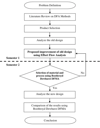
1.5 Project Methodology
The methodology of study is shown in Figure 1.1.
Figure 1.1: The project flowchart Problem Definition
Literature Review on DFA Methods
Product Selection
Analyze the old design
Proposed improvement of old design using Effort Flow Analysis
Yes
No
Analyze the new design
Comparison of the results using Boothroyd Dewhurst DFMA Semester 1
Semester 2
Selection of material and process using Boothroyd
Dewhurst DFMA
The project will be accomplished in two continuous semesters. The milestones of project activities are shown in Gantt Chart in Appendix A1. In the first semester, the project starts with the problem definition arises with the current DFA methodologies that aid in redesigning a product for part combination. This matter also has been looking into the perspective of global issues currently debate among the technological practice. To investigate these problems, literature review on several DFA methodologies is done on; the Boothroyd Dewhurst DFMA Method, the Lucas DFA Evaluation Method, and the Hitachi Assemblability evaluation Method (AEM), and the Effort Flow Analysis (EFA) Method. However, the study of EFA will be discussed exclusively, which aligns with the scopes of study.
For the purpose of the project, an existing product design is selected that consists of varying degrees of relative motion exist in its product’s part and thus, makes the product evolution more challenge. The product’s mechanism, function of each part, and the weaknesses of the mechanism have been critiques in order to investigate for the possibility of part combination. To guide toward piece count reduction through part combination, effort flow analysis method is used. There are several guidelines need to be followed, which are referred to the relative motion characterization. This topic will be discussed in details explanation and an example of the existing product is demonstrated in step by step manner. At the end of the process, several new designs are been proposed as initial product evolution.
1.6 Significance of Findings
The application of DFA guidelines is known to lengthen the concept development time because a lot of time was spent during the redesign effort but somehow it helps to shorten the other stages of product development. During the concurrent development of a product’s parts, the product time-to-market is determined by the development of the most complex part. The manufacturing costs will increase relatively, primary because of assembly, and ultimately market share will be lost. In the era of globalization, everything needs to be faster, cheaper and better.
Design decisions made during product configuration and detail design largely determine the choice of material, process, product quality, and recycling method etc., all of which contribute to the product lifecycle cost. Early cost estimates enable designers to search for design configurations that minimize cost objectives while optimizing other design specifications. The search by manufacturers for the combination of low cost, high quality, and reliability in products is now become an essential characteristics for product’s success in today’s highly competitive global market. Therefore, the reduction of the number of parts in a product is the best opportunity for reducing manufacturing costs. Less parts implies less purchases, inventory, handling, processing time, development time, equipment, engineering time, assembly difficulty, service inspection, testing, etc.
The effort flow analysis has brought new generation of DFA methodologies to much broader scope, which addressing part combinations that experience varying degrees of relative motion. The effort flow analysis offer part count reduction is based on the use of one piece structures and selection of manufacturing processes such as injection molding, castings, and powder metallurgy, etc.
1.7 Report Structure
This report is attempted to strike a balance between theory and practice through the emphasis of the DFA methods. The report consists of seven chapters. Chapter 1 is about introduction to the project. An overall picture of the project can understand within this chapter. Objectives and scopes are developed in reflects to the problem statement while the significant of the project is described at the end of chapter.
Chapter 2 is devoted to a literature review on DFA Methodologies. The DFA methodologies of Boothroyd Dewhurst DFMA, Lucas DFA, Hitachi AEM, and Effort Flow Analysis are overviewed. In this chapter, the application of Boothroyd Dewhurst DFMA is used to evaluate the performances of the existing product design and for selection of processes and materials for design for manufacture.
In Chapter 4, Effort Flow Analysis (EFA), the theory of evaluation complete with example is demonstrated in step-by-step manner. The coverage is to highlight the categories of relative motion and the systematic guidelines of the method for successful part combination.
Chapter 5 is discusses about the Design Concept Selection. Outcome from the EFA, there are several design concepts under consideration for further development. There is methodology called Pugh concept selection used to justify the best design concept selection.
Once it has been agreed to develop an idea for a product concept, the next step is to develop its design for ease of manufacture. This issue is discussed in chapter 6, Design for Manufacture (DFM). The methodology of Boothroyd Dewhurst DFMA is established for processes and materials selection.
1.8 Summary