Analysis of Human Spine Image Using Finite
Element Modelling
T.Rajesh Kumar1, E.Vignesh2, Dr.P.Suresh2
Assistant Professor, Department of Mechanical Engineering, Karpagam College of Engineering (Autonomous)
Othakkalmandapam, Coimbatore, Tamil Nadu, India1&2
Professor, Department of Mechanical Engineering, Karpagam College of Engineering (Autonomous)
Othakkalmandapam, Coimbatore, Tamil Nadu, India3
ABSTRACT: A biomechanical model has been developed for optimising the lifting posture for minimum effort and presented in this paper. The model has been validated with practical data available from literature. The model can also be used to predict the lifting capabilities of individuals. A finite element model to study and analyse the stresses on Functional Spinal Unit has also been developed. The effort to be taken for in vivo and in vitro data collection and analysis are reduced considerably in the finite element modelling.
KEYWORDS: Magnetic Resonance Imaging, Lumbar Spine, Finite Element Modelling, Pro/E
I. INTRODUCTION
Manual Material Handling (MMH), especially lifting, poses a risk to many and considered the prime cause of back pain and various other joint impairments. This in turn leads to increased worker compensation and loss of productive man-hours. Approximately one third of all jobs in industry involve MMH. Low back pain is one of the most prevalent and costly work related injuries. The study of the lifting posture, the amounts of weight the man can safely lift are the areas concentrated on by Researchers. Of all Manual Material Handling (MMH) activities, lifting is considered to be a major cause for low back pain and spinal injuries. Annual costs associated with back pain in US alone ranged from 20 billion US$ to 50 billion US$ [1]. Although epidemiological studies have suggested possible causes, the actual mechanisms by which the lumbar spine is injured during load cycle resulting in low back pain remains unknown. However, the response of the disc to loading conditions that occur during lifting is difficult to measure in vivo and in vitro and has not been investigated using any model so far [2]. Here, an attempt has been made to analyse FSU using a suitable finite element modelling for sagittal plane lifting activity. Many universities and institutions around the world are producing finite element models of the spine for various analyses. For example, there are FEMs being created to study the effects of automobile accidents on the spine. The geometry, material properties and loading conditions of the lumbar spine are very complex. Though the FEM is a well-established method, various simplifications have to be used and assumptions are to be made [3]. The spine is acted upon by muscle forces. In vitro experiments, almost never consider the muscle forces. It is reported that, experimentation has shown that in lordotic spine during prolonged standing, the impacted joints at each segment level bear an average of 16% of the axial load [4].
Hutchinson and Littlefield [5] tried to simplify FEM of vertebral body by modelling it as a cylinder. This study was conducted to determine the stresses induced in a previously injured spine during pilot ejection. Initially Hutchinson and Littlefield started FEM by importing data
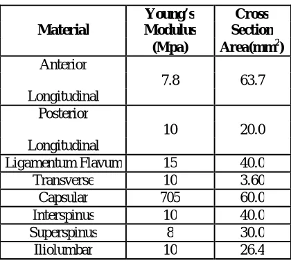
Table 1: Empirical Quantities of Spine Young’s Cross Material Modulus Section
(Mpa) Area(mm2) Anterior
7.8 63.7 Longitudinal
Posterior
10 20.0
Longitudinal
Ligamentum Flavum 15 40.0
Transverse 10 3.60
Capsular 705 60.0
Interspinus 10 40.0
Superspinus 8 30.0
Iliolumbar 10 26.4
Literature review shows that a few researchers have applied FEM for analysis of lumbar L2/L3 and cervical spine [7]. However, studies on the combined L1/L2/L3/L4/L5/S1 (FSU), FEM analyses are not found to have been done.
II. FUNCTIONAL SPINAL UNIT (FSU)
Spinal unit otherwise known as vertebral column consists of 24 separate bony vertebrae together with 5 fused vertebrae, which form the sacrum and usually 4 fused vertebrae, which form the coccyx, 24 separate vertebrae are interlaced with inter-vertebral discs. Normally the column appears symmetrical in the frontal plane and has characteristic curvatures in the sagittal plane. Curvatures provide natural shock absorbency and flexibility. Three principal functions of vertebral column are to
1. Support the human in the upright posture
2. Allow moment and locomotion 3. Protect the spinal cord.
Knowledge of the load-displacement behaviour of spine and its components is required for biomechanical analysis of spine function.
Description of spine
The following two sections detail the general configuration of the spine and specifics of the spine according to region.
General description of spine
The spine consists of 33 vertebrae (Fig.1), in all, including those of the sacrum and the coccyx. The upper portion of the spine is called the cervical region, is made up of 7 vertebrae (C1-C7), while the middle portion of the spine consists of
12 vertebrae (T1 -T12) and is termed as Thoracic region. The next 5 vertebrae (L1-L5) make up the Lumbar region. The
Sacral region and coccygeal region are made up of 5 fused Vertebrae (S1-S5) and 4 fused vertebrae (C01-C04),
Fig. 1: The Spine
The individual vertebrae of the five regions are labelled by the particular region and location within that region, e.g., the second vertebra of the cervical region is C2. Most of the load carried by the spine is supported by the vertebral
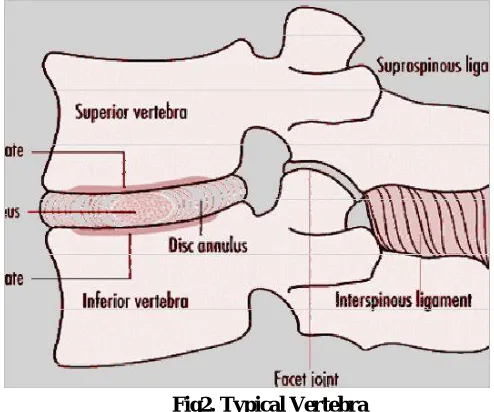
body, which also serves as a resting-place for the intervertebral discs. Muscles and ligaments used in rotation and lateral flexion are attached to the spine by the transverse processes (2 per vertebra) that extend laterally from the point at which the pedicles and laminae are joined. The remaining vertebral process is the spinous process. The spinous processes vary in size, shape, and direction from one region of the spine to the next. Like the transverse processes, the spinous processes act as levers to which muscles are attached. However, these muscles control posture and flexion/extension, lateral flexion and rotation movements of the spine. The spinous processes are also the bones that can be felt as protrusions down the centre of the back. Each vertebra has a thin outer layer of compact (cortical) bone, which encases a soft, trabecular (cancellous) bone containing red bone marrow as seen in Fig.2.
Fig2. Typical Vertebra
vertebral bodies.
Common Spinal Problems
The spine can become injured in a variety of ways. Spinal injuries can be the result of a sports-related occurrence, the lifting of a heavy object, an auto accident, or ejection from an aircraft. Ultimately, the spine sustains an injury due to the stresses imposed upon it becoming greater than the material strength of the spinal components.
Disc herniation or herniated nucleus pulposus is made of two parts, a hard outer layer and a soft central core. A tear in the outer layer can allow the soft center portion of the disc to leak. This ruptures (herniated) disc may press up against a spinal nerve causing pain, numbness and tingling or weakness in the arms or legs. Spinal stenosis is a form of arthritis in the spine. The hole or canal where the spinal cord runs becomes narrow. Bony growths on the vertebra narrow this opening and cause pressure on the spinal cord and/or nerves. Patients may have pain, with numbness and tingling or weakness to the arms or legs. Spinal stenosis may occur at any level of the spine, but is more common in the lumbar and cervical spine. Degenerative disc disease is another form of arthritis to the spine. The discs between vertebra shrink. Degenerative disc disease is often described as a “wear and tear” condition. It is a normal part of aging, but can also be caused by injury to the disc. Symptoms include pain in the involved areas of the spine and, in some instances, pain or numbness to the arms or legs. Loss of flexibility is also typical. Spondylolisthesis is an abnormal spinal condition in which one vertebrae lips or is improperly aligned over another vertebrae. If abnormal motion allows this vertebrae to slip back and forth spinal nerves may be affected causing pain, numbness and tingling or weakness in the legs. Many individuals do not have symptoms with this condition while others experience long standing back pain. Spondylolisthesis is most common in the lumbar area. Scoliosis is a condition where the natural curves of the spine are affected. A normal spine has three natural curves that keep the body balanced, but in scoliosis there is an abnormal side-to-side curve. As a result one may have back pain, an uneven waist, uneven shoulders, prominent shoulder blades or elevated hips. Kyphosis involves the backwards bending of the spine. Normally kyphosis is seen in the thoracic region. When this natural curve is increased and structural changes in the vertebrae occur, this kyphosis occur and this disease is also known as Scheuermann’s disease. This describes the wedging and irregular edges of the vertebrae as seen on x-rays. This spinal disorder is more commonly known as a “round back” deformity of the spine.
Spinal instability is a condition where vertebrae of the spine become unstable. This can come from an injury or a degenerative disorder. The normal structure and function of the spine is interrupted and deformity results. In some cases the spinal cord and/or spinal nerves are at risk for injury. Symptoms include pain, numbness, weakening and, in some cases, nerve damage.
Injuries Caused By Lifting
Lifting has the potential to contribute to injury. Large extensor moments about the joints of the lumbar vertebral column are produced during lifting by the paravertebral musculature to overcome the flexor moment caused by the weight of the upper body and load. Injury to musculo-ligamentous structures occurs as a direct consequence of the high forces involved. These high forces also result in large compressive and shear forces acting between each pair of vertebrae, which in turn lead to endplates failure and disc prolapse.
Anthropometry of FSU
Functional Spinal Unit (FSU) consists of Lumbar and sacrum region. Lumbar vertebral column comprises of five vertebrae and the intervertebral discs. It has a characteristic curvature called lumbar Lordosis. In the standing position, the sacrum is tilted forward so that its upper surface is inclined forwards and downwards forming an angle between the top of the sacrum and the horizontal which varies between 50 – 530.
Factors contributing to the normal shape of the lumbar lordosis
1. L5 vertebral body is wedge shaped, the anterior body wall is 3 mm higher than the posterior body wall. This brings the upper surface of the L5 body closer to the horizontal plane than the upper surface of the sacrum
2. In addition, the L5/S1 disc is also wedge shaped, the anterior vertical height is 6~7 mm greater than its posterior height. As a result of the wedge shape of the disc, the lower surface of the vertebral body is not parallel to the upper surface of the
sacrum, so that the angle formed between the two surfaces may vary between 6~290 and has an average size of 160.
3. Each vertebra above is inclined slightly backwards in relation to the vertebrae below.
In the standing position measurement for radiographs of the angle between the top of L1 and the sacrum have been recorded as 670(±30 SD) in Children and 740(±70 SD) in young males. Development of lumbar lordosis begins as an infant starts to stand, usually between 12-18 months of age and it continues to develop until the completion of spinal growth normally between 13-18 years. In old age, the lumbar column usually becomes flattened.
Modelling and Analysis Of FSU
Finite Element modeling is the modeling of a continuous system, which has a infinite number of degrees of freedom, using a representative geometry of that system made up of a finite number of smaller elements and node points. The more elements in the model, the more accurate it is. The material properties, displacements and other system characteristics are represented by mathematical functions between nodes. This finite element model can then be used to determine the stress, strain, and displacement of the structure resulting form external loading [5]. Once the Finite Element Model has been created and the system characteristics have been established in the model, a global stiffness matrix can then be formed for the whole structure. Given the forces and boundary conditions, the unknown displacements at each of the node points can then be used to determine the stresses and strains acting on each element [5]. Initially, the Finite Element Models have been applied to aircraft structures and then FEM rapidly spread to Civil Engineering and Mechanical Engineering. FEM is gaining acceptance as a valuable tool to study static, dynamic as well as cyclic problems. Only recently FEM has been seriously applied to Biomechanical problems. The following assumptions are made while modelling FSU:
1. Vertebrae is considered as having elliptical cross section. Actually this is an improvement over Hutchinson-Littlefield model [8]. Ellipse gives a closer approximation.
2. Upright standing posture is assumed for modelling.
With the advent of Magnetic resonance imaging (MRI), one can measure internal organs and bones with high resolution and accuracy. MRI is a non-invasive imaging approach. Cross sectional size of L1 lumbar vertebra are measured from an adult subject using MRI scan. It is found to be 40mm Major and 32 mm minor. Based on the anthropometric proportions, other dimensions are arrived at.
There are host of software for 3D modelling and here Pro/Engineer is preferred because of its simplicity and seamless integration with analysis package Pro/ Mechanica. Whole FSU is modelled in parts and assembled according to the properties of Lumbar spine. Assembled model is transferred to Pro/Mechanica environment.
The boundary conditions are
1. Lower vertebral disc (L5/S1) of the L5 body was fixed.
2. All other vertebral bodies and discs are allowed all degrees of freedom.
4. The axial force due to body weight is calculated (at L5/S1) as follows:
From the above conditions forces along spine direction are
F – ES - Bcosθ - W cos θ = 0 --- (1) Moment:
ES x l = Bb+ Ww ---- (2) Where,
ES = Erector spinae muscle force F = Disc compressive force
B = Force from upper body weight W = Force from lifted weight l = Length of moment arm from ES
b = Length of moment arm from centre of gravity of the body weight w = Length of moment arm from lifted weight
θ = Angle made by the force of body weight with erector spinae muscle force
B = 0.65 x M x g Where,
M = The body mass of the individual g = Acceleration due to gravity
From literature, for a grown up normal adult l = 6 cm, b = 25 cm
θ = 520 (Helander et al 1984).
III. RESULTS AND DISCUSSION
Calculations are as shown below:
ES x 0.06 = (400 x 0.18) + (98 x 0.35) ES = 1772 --- (3)
Substituting the ES value in equation 1. F – 1772 – 400 cos520 – 98 cos 520 = 0
F = 2079 N --- (4) Axial force on L1 is 228 N @ 11 %
Maximum vonmises stresses are found at L5/S1 and L4/L5 and it’s magnitude found to be 3.05 Mpa.
As like above conditions the Maximum vonmises stresses are found at L5/S1 and L4/L5 and it’s magnitude found to be 4.083 Mpa for lifting a load of 20 kg.
The experimental study made on cadaveric spines under similar condition has been used for comparison [8]. Fig.5 shows the comparative study results of the study with the experimental study. The results from this study are very close to that of Experimental study. X- axis scale 1 unit is equal to 10 kg and Y-axis 1 unit is equal to 1 mpa.
IV. CONCLUSION
Although epidemiological studies have suggested possible causes, the actual mechanism by which the lumbar spine is injured during load cycle resulting in low back pain, remains unknown. However, the response of the disc to loading conditions that occur during lifting is difficult to measure in vivo and in vitro methods and has not been investigated so far. Therefore, a finite element model that can predict the loading behaviour of Functional Spinal Unit (FSU) has been developed. The finite element model of the FSU is found to confirm with the earlier works using cadaveric method [8], thus proving the usefulness of this methodology for biomechanical modelling. The effort to be taken for the in vivo and in vitro data collection and analysis are reduced multi fold in the finite element modelling. The study can be extended to include the loading of the muscles. Same FE model can be extended to all Sagittal plane lifting activity. Thus, the study established the viability of FEM methodology for analysing FSU.
REFERENCES
1. Miller J.A. and Albert B. Schultz (1997), ‘Biomechanics of Human spine’, Basic 2. orthopaedic Biomechanics’, 2nd Edition, Lippincott – Raven publishers, pp. 353-385.
3. Williams J.R., Natarajan R.N., Andersson G.B.J. (2002), ‘Biomechanical Response of a Lumbar Motion Segment Under Repetitive Loading conditions - A Finite Element study’, Tenth Annual Symposium on Computational Methods in Orthopaedic Biomechanics, university of Texas southwestern Medical Center, Dallas.
4. Jenna Bowling, Tony Chao and Robin Kinsey (1995), ‘Analysing the spine under aircraft ejection loading’, Project reports. The University of Texas at Austin.
5. Oliver J. and Middleditch A. (1991), ‘Functional Anatomy of the spine’, Buttetworth Heinemann, pp. 1 – 79.
6. Cantu C. (1997), ‘An analysis of the spine subjected to Ejection seat loads’, Project reports, The University of Texas at Austin.
7. Shirazi-Adl A., Ahmed A.M. and Shrivastava S.C. (1986), ‘A Finite Element Study of the Lumbar Motion Segement subjected to pure sagittal plane moments’, Journal of Biomechanics, Vol. 19, No. 4, pp. 347.
8. Carlos G., Lopez-Espina and Amirouche F. (2000), ‘A three-dimensional parametric model of the cervical spine for finite element analysis’, Project reports, University of Illinois at Chicago.
9. Antonious Rohlmann, Jorge Callisse and George Bergmann (1999), ‘Estimation of trunk muscle forces using the finite element method and in vivo loads measured by telemeterised internal spinal fixation devices’, Journal of Biomechanics, vol. 32, pp. 727 – 731.
11. Punarselvam E and Suresh P. ‘Edge Detection of CT Scan Spine Disc Image using Canny Edge Detection Algorithm Based on magnitude and Edge Length’, International Conference on Trends in Information Sciences and Computing (TISC-2011),8th & 9th December 2011, Sathyabama University, Chennai, pp. 150-154.
12. Suresh P., Kesavan R., and M.Madheswaran., ‘Finite Element Modeling and Analysis of Magnetic Resonance Imaging of Lumbar Spine Using Pro/E Software’, International Journal of computational Intelligence and health Care Informatics (IJCIHCI), Vol.I, No.1 Page No: 50-56, 2008.
13. Suresh P. and Kesavan R., ‘Ergonomic Experimental Analysis of Eye Strain on VDT users: A strategic Prevention Perspective’, ICFAI Journal of Business Strategy, Vol.IV, No.3 Page No: 63-72, September 2007.