362
To study performance development of draft tube by
using ANSYS CFD
Swati Sapkal 1, Kishor Sontakke 2,
PG student1, Associate Professor 2,Department of Mechanical Engineering,PLITMS,Buldhana,Maharashtra,India
Email: [email protected]
Abstract- . In order to utilize the available energy of water to its fullest, there should not be any loss of energy of water in the hydraulic passage of hydro turbines. Draft tube are located at exit of runner to connect turbine and tail race providing closed flow of varying cross sectional area. The development in the design of turbines leads to different shape of draft tube. This helps to recover as much energy as possible. By varying length to inlet diameter ratio of Straight Divergent type draft tube, the pressure and velocity variation at inlet and outlet is studied to attained greater efficiency. Greater efficiency gives greater performance to draft tube. In this paper, we tried to present how the alternative designs of draft tube can be studied by using the analytical and computational power of the software. Computational fluid dynamics (CFD) simulation software allows you to predict the impact of fluid flows on draft tube throughout design and manufacturing. Now the CFD codes have also matured to provide substantial insight to hydro turbine design and development applications
Index Terms- CFD, Hydro turbine, Draft tube, Performance.
1. INTRODUCTION
1.1 Need of the Project
A demand in Turbomachinery performances is increases now a days. The use of hydraulic turbines for the generation of power has a very strong historical tradition. A higher efficiency is commonly expected for hydraulic turbines. A draft tube is one important part of a turbine, which is used to transform water into energy. It's found within the piping system in jets, dams, or anywhere else where turbines help do difficult mechanical work. Turbines need to have a minimum amount of water to propel them in order to produce enough energy. Without these tubes, the pressure could drop because of lack of water, and in turn, the entire turbine could fail to work and power could be lost. Under such conditions, the improvements are coming from small details leading to competitive products based on new control techniques. Moreover, many of the hydraulic turbines have to be refurbished in the next period .Therefore; new demands on the deregulated energy market make it attractive to improve energetic, cavitational and dynamic performances of the hydraulic turbines over a wide operating range [1].
The Aim of present work is to show that computational fluid dynamics is a excellent tool to analyze the performance parameters of draft tube. Which in turn helps to better working of draft tube with maximum efficiency. ANSYS CFX is a high-performance computational fluid dynamics (CFD) software tool that delivers reliable and accurate solutions quickly and robustly across a wide range of CFD and multi-physics applications. CFX is recognized for its outstanding accuracy, robustness
and speed with rotating machinery such as pumps, fans, compressors, and gas and hydraulic turbines[2]
1.2 Literature Review
A large number of investigations were carried out on straight diffusers during the period 1909 to 1929 leading the design of various draft tubes. The use of straight tubes was restricted to turbines of medium and small diameters because due to increase of the diameter of the runner D1, the length of the tube became so large that it is irrational to construct such tubes. The recovery of the kinetic energy of axial and rotational flow can be best achieved in bell mouth tubes. The use of such tubes for large runner diameters has again restriction due to support problem of such large dimensions and weight. All these problems are overcome by elbow draft tube for large diameter hydraulic turbines[3].
(1) Ciocan et al.presented a CFD (Computational Fluid Dynamics) methodology to study the unsteady rotating vortex flow in the draft tube of a Francis turbine at part load conditions. They performed unsteady Reynolds-Averaged Navier-Stokes (RANS) simulation for the flow and validated the same with experimental results[1].
(2) Qian et al. studied the three-dimensional multiphase flow field in a Francis hydraulic turbine. They especially investigated the pressure pulsation in the draft tube, the front-runner, the guide vane [4].
363
of a medium and low head reaction turbine isthe draft tube. Since the draft, tube losses have an important impact on the overall turbine performances [3].
(4) Vu and Retieb et al.clearly showed that the hydraulic losses in the draft tube are dominant at off-design conditions. Galvan noticed that it is still a challenge to get the optimal flow distribution at the draft tube inlet, which gives the best machine performance over a range of operating points. Therefore, it is essential to develop a suitable parameterization of the swirling flow downstream the turbine runner in order to be analyzed the draft tube response to various inflow configurations.
(5) Abhas Chincholikar et al.used Ansys CFX code to study The numerical flow simulation for 3D viscous turbulent flow in elbow draft tube by varying its parameters like length and height at different mass flow rate .The draft tube efficiencies and losses are computed from pressure and velocity distributions and presented graphically to study the effect of geometrical parameters on draft tube performance. The predicted geometrical parameters from numerical simulation for the best performance are closely matching to the geometry of draft tube used in most of the hydro power stations. The mass flow rate has nearly no effect on efficiency and loss in draft tube. The best performance is achieved close to height ratio of 2.24 and length ratio L/D1 of 6.0. It is found that most of the hydro power plants has used elbow draft around the to height ratio of 2.24 and length ratio L/D1 of 6.0.[5]
2.PROBLEM FORMULATION
In the context of hydraulic turbine rehabilitation projects, Computational Fluid Dynamics (CFD) is a valuable tool to assess the efficiency of the existing stationary components and their interaction with the runner prior to model testing. It is well accepted today that CFD codes give reliable predictions when used to compare hydraulic designs, in particular for the converging water passages of a turbine such as the inlet casing or the stay vanes guide vanes tandem cascade. On the other hand, for diverging water passages such as the draft tube, CFD predictions have to be interpreted with care, in particular in the case of low head turbines for which the runner draft tube coupling strongly influences the overall turbine hydraulic behavior.
The main objective is therefore not to push forward the limits of CFD capabilities but rather
to identify how simulations can be optimized to yield reasonable results in a limited time period or with limited resources. Recently, the use of modern techniques like computational fluid dynamics (CFD) for predicting the flow in these machines has brought further substantial improvements in their hydraulic design, in the detailed understanding of the flow and its influence on turbine performance and in the prediction and prevention of cavitation inception. The efficient application of advanced CFD is of great practical importance [6].
Poor draft tube design may lead to separated and unstable flow inside the tube, reducing the efficiency and stability of the turbine-system [7].
3. DESIGN AND CALCULATION 3.1 Boundary Conditions
The boundary condition for draft tube analysis have been applied.In boundary condition Inlet mass flow rate is given 1000 kg/sec.Average static pressure is specified at outlet of draft tube as outlet boundary condition. All the walls in the geometry is assumed as smooth and no slip.
3.2 Methodology
by keeping L/D3 constant and by varying divergence angle 2θ,the Pressure and velocity variation is studied in each case and from that the optimum value of inlet and outlet pressure and velocity is calculated which gives greater efficiency of draft tube.
The analysis for the straight divergent draft tube will be done as follows:
(1)CAD model of existing Draft Tube was imported for the analysis.
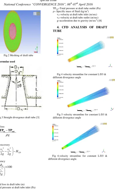
(2)Mesh was generated for the analysis in ICEM CFD tool. (Fig 2)
(3)CFD analysis was performed in CFD post 14.0.
364
Fig.2 Meshing of draft tube 3.3 Formulae used
Fig.3 Straight divergence draft tube [3]
Head loss
g
ρ
−
=
in outLD
TP
TP
H
Head recovery
2 2
3 5
2
2
d LD
v
v
h
H
g
g
∆ =
−
−
Efficiency
2 3
100
2
d D
h
v
g
η
=
∆
×
Where,
HLD=Head loss in draft tube (m)
TPin=Total pressure at draft tube inlet (Pa)
TPout=Total pressure at draft tube outlet (Pa)
[image:3.612.145.548.55.717.2]ρ= Specific mass of fluid (kg/m3) v3=velocity at draft tube inlet (m/sec) v5=velocity at draft tube outlet (m/sec) g=acceleration due to gravity (m/sec2) [8]
4. CFD ANALYSIS OF DRAFT
TUBE
Fig 4 velocity streamline for constant L/D3 & different divergence angle
Fig 5 velocity streamline for constant L/D3 & different divergence angle
[image:3.612.121.292.92.254.2]365
Fig 7.Pressure contours for constant L/D3 & different [image:4.612.104.299.220.329.2]divergence angle.
Fig 8. Pressure contours for constant L/D3 & different divergence angle.
Fig 9.Pressure contours for constant L/D3 & different divergence angle.
Fig 4,5.6 shows the velocity streamline for L/D3 equals to 14,19,25 and divergence angle equals to 3,5,7 degree.
Fig 7,8,9 shows the velocity streamline for L/D3 equals to 14,19,25 and divergence angle equals to 3,5,7 degree
0 20 40 60 80 100
0 2 4 6 8
E
ff
ic
ie
n
cy
Divergence Angle
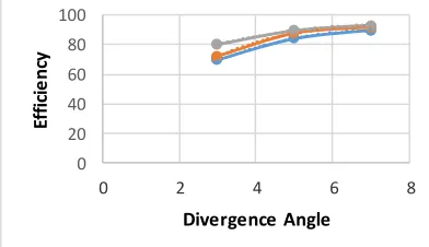
Fig 10.Graph plotted between efficiency & divergence angle
Figure shows the graph plotted in between the efficiency with diffuser angles 3,5,7 degree and constant L/D3 ratios 14,19,25
5.CONCLUSION
From above analysis it has been concluded that as divergence angle increases efficiency of draft tube also increases. At divergence angle 7 degree and L/D3 25 there is no increase in the efficiency of draft tube.
It shows that the divergence angle of straight tubes depends on the length L. The CFD analysis results give good agreement with experimental readings, which reduce higher cost experimentation. The same analysis has been performed for each concepts with same boundary conditions.
6 REFERANCES
[1] Tiberiu Ciocan, Romeo Susan-Resiga, Sebastian Muntean “Improving draft tube hydrodynamics over a wide operating range” proceedings of the Romanian academy, series a, volume 15, number 2/2014, pp. 182–190.
[2]http://www.ansys.com/Products/Fluids/ANSYS -CFD
[3] tian xiaoqing,1 zheng yuan,1 pan huachen,2 and sun bin ,“numerical and experimental study on a model draft tube with vortex generators” Hindawi publishing corporation advances in mechanical engineering volume 2013.
[4] O. Kirschner, A. Ruprecht, “Velocity Measurement with PIV in a Straight Cone Draft Tube”, 3rd German - Romanian Workshop on Turbomachinery Hydrodynamics, Timisoara, ROMANIA, May 10-12, 2007.
[5]Vishnu Prasad,Ruchi Khare Abhas Chincholikar, “Hydraulic performance of elbow draft tube for different geometric configurations using CFD” Proceedings of 8th International Conference by IGHEM, IIT, Roorkee,2010.
[5] J H Jeon, S S Byeon and Y J Kim, “Effects of draft tube on the hydraulic performance of a Francis turbine”, 6th International Conference on Pumps and Fans with Compressors and Wind Turbines.
[6] D. Stefana, P. Rudolfa, A. Skotakb, L. Motycakb“Energy transformation and flow topology in an elbow draft tube”, Applied and Computational Mechanics 6 (2012) 93–106.
[image:4.612.103.299.362.475.2] [image:4.612.111.307.575.688.2]