Active and Reactive Power Control of a DFIG for
Variable Speed Wind Energy Conversion using a
New Controller
N.Hamdi,
Electrical Laboratory of Constantine “LEC”, Department of Electrical Engineering, University
Constantine 1, 25010 Constantine, ALGERIA,
A .Bouzid,
Electrical Laboratory of Constantine “LEC”, Department of Electrical Engineering, University
Constantine 1, 25000 Constantine, ALGERIA,
ABSTRACT
This paper presents a vector control direct (FOC) of double fed induction generator intended to control the generated stator powers. This device is intended to be implemented in a variable-speed wind-energy conversion system connected to the grid. In order to control the active and reactive power exchanged between the machine stator and the grid, the rotor is fed by a bi-directional converter. The DFIG is controlled by standard relay controllers. Details of the control strategy and system simulation were performed using Simulink and the results are presented in this here to show the effectiveness of the proposed control strategy.
Keywords
Vector control indirect (IFOC), doubly fed induction
generator (DFIG), variable-speed wind-energy, standard relay.
1.
INTRODUCTION
THE most important advantages of the variable speed wind turbines as compared with conventional constant speed system are the improved dynamic behavior, resulting in the reduction of the drive train mechanical stress and electrical power fluctuation, and also the increase of power capture. One of the generation systems commercially available in the wind energy market currently is the doubly fed induction generator (DFIG) with its stator winding directly connected to the grid and with its rotor winding connected to the grid through a variable frequency converter as shown in Fig.1. One of the most advantages of this system is that the rating of the power converter is one third of that of the generator [1].
The doubly fed induction generator is widely used for Variable-speed generation and it is one of the most important generators for wind energy conversion systems. Both grid connected and stand-alone operation is feasible [2].
Field oriented control, published for the first time by Blaschke in his pioneering work in 1972, consists in adjusting the flux by a component of the current and the torque by the other component. For this purpose, it is necessary to choose a d-q reference frame rotating synchronously with the rotor flux space vector, in order to achieve decoupling control between the flux and the produced torque. This technique allows to obtain a dynamical model similar to the DC machine [3].
The regulation of the flux can be direct or indirect. In the indirect control, the flux is not estimated or reconstructed but fixed in open loop system.
The objective of this work lies in the modeling, simulation and decoupled control of active and reactive powers for a doubly- fed induction generator using the standard relay controllers and to make a comparison with PI controllers.
The reminder of the paper is organized as followed: In section II, the DFIG model in an arbitrary reference-frame is presented. In section III the turbine wind model is presented. In section IV the control strategy for this system is proposed. The calculus of controller is presented in section V. Finally, the results and conclusions are drawn.
Fig1: DFIG variable speed wind energy conversion IFOC
control
2.
MATHEMATICAL MODEL OF THE
DFIG
The equivalent two-phase model of the symmetrical DFIG, represented in an arbitrary rotating d-q reference frame is [4 ,5,6,7]:
sd s sq sq s sq
sq s sd sd s sd
dt d dt d i R V
dt d dt d i R V
(1)
rd r rq rq r rq
rq r rd rd r rd
dt d dt d i R V
dt d dt d i R V
(2)
rd sd r rs sr s rd sd i i L M M L . (3) rq sq r rs sr s rq sq i i L M M L . (4)
The electromagnetic torque is expressed as:
)
(
2
3
sd sq sq sdem
i
i
C
(5)
The active and reactive power is expressed as:
sq sd sd sq sq sq sd sd
i
V
i
V
Q
i
V
i
V
p
(6)
3.
WIND TURBINE MODEL
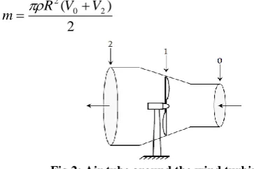
The air tube around a wind turbine is illustrated in Figure 2. Assuming that the wind speed (V1) crossing the rotor is the average value between the upstream speed (V0) and the downstream speed (V2), the moving air mass of density ρ crossing the surface S (S = πR2) per unit of time is given by [8]:
2
)
(
0 2 2V
V
R
m
(7)
Fig 2: Air tube around the wind turbine
By applying the conservation of mass to the case of the Fig.2 we have: 2 2 1 1 0 0
V S VS VS
(8)
Where Vi is the wind speed at station i and
i
S is the cross
section area of station i. It is considered thereafter that 1 V V et 1 S S
The pressure force of the turbine rotor is given by:
2 2 2 2 0
0V SV
S
F
(9)
Or equivalently, using Eq. (8):
V0 V2
SVF
(10)
Assuming that the speed of the wind crossing the rotor is equal to the average between the non-disturbed speed of the wind in the front one the turbine
V
0 and the speed of the wind after the passage through the rotorV
2, that is to say:2
2 0V
V
V
(11)
And customarily defining an axial induction (or interference) factor, a, as the fractional decrease in wind velocity between position 0 and position 1, by:
0 0
V V V a
(12)
Eq. (10) can be rewritten in a more useful manner:
a
a
SV
F
4
1
2
1
2 0
(13)
The wind power extracted by the rotor is the product of the pressure forces the turbine rotor and the speed of the wind in the plan of the rotor:
3
20 0
2
0 4 1
2 1 1 1 4 2 1 a a SV a V a a SV FV
Ptu
(14)
Theoretically, a non-disturbed wind crosses this same surface
S without reduction of the speed which is 0
V
, the corresponding theoretical powerP
thwould be then:3 0
2
1
SV
P
th
(15)
The ratio between
th
P
andtu
P
, called the power coefficient Cpis then:
21
4a a
P P C
th tu
p
(16)
The result is shown in Fig. 3.
The power coefficient has a maximum . This theoretical value is well-known as ‘Betz limit’ which determines the maximum power that can be extracted from a
given wind speed. This limit cannot be reached in reality.
Therefore, each wind turbine is defined by its appropriate Cp
versus the tip-speed ratio λ, where:
v
R
turbine.
(17) [image:2.595.54.236.368.489.2]0 0.1 0.2 0.3 0.4 0.5 0.6 0.7 0.8 0.9 1 0 0.1 0.2 0.3 0.4 0.5 0.6 0.7 a Cp
The mechanical power will be written then:
2
3 0 2V
R
C
C
P
P
tu th p p
(18)This expression allows obtaining a set of characteristics presenting the generator mechanical power depending both on the wind and rotating speeds. The result is shown in Fig.4.
0 2 4 6 8 10 12 14 16 18 20
0 0.05 0.1
ratio of speed
[image:3.595.63.278.190.301.2]po w er c oe ffi ci en t ( C p)
Fig 4: Characteristics of mechanical power versus wind and rotating speeds
4.
VECTOR CONTROL OF THE DFIG
FLUX STRATEGY
The technique of vector control is based on a control law leading to a characteristic adjustment similar that of a DC machine with separate excitation. The vector control with statoric flux oriented concerns, evidently, the power returned on the network side of the stator.
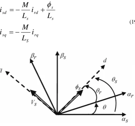
The constraint of the stator flux orientation can be written as, and , which consider that the assumption of the constant stator flux [9]. After orientation the stator and rotor fluxes are presented in Fig.5. The expressions of the statoric currents may be given as:
[image:3.595.56.273.505.706.2]rq S sq s s rd s sd
i
L
M
i
L
i
L
M
i
(19)Fig-5: DFIG vector after orientation
In fig.5, one distinguishes the following elements as: Absolute position of the rotor.
, : statoric flux positions and mechanical rotor position
Neglecting the per-phase statorique ,that's the case for medium power machines used in wind energy conversion systems [11].
In Taking account of the orientation of flux and the stator voltage (constant value imposed by the network) as shown in Fig. 5, we can rewrite as follows:
s s s s sd
V
dt
d
V
sqV
0
(20)
The expression of active and reactive powers of the stator can then be written only in terms of rotor currents like
s s s rd s s rq s s s
L
V
i
L
M
V
i
L
M
V
P
2 sQ
(21)
It follows from expression (21) as control for active and reactive power of the stator is decoupled. The stator active power produced by the machine is controlled by the component , the reactive power can be controlled by the component and possibly controlled to zero to obtain a unitary power factor at stator.
The expressions of rotoric voltages as a function of rotoric currents are given as follows:
rq s r r rd s r rd r rd I L M L w dt dI L M L I R V
2 2
s s s r rd s r r rq s r rq r rq L w MV w I L M L w dt dI L M L I R
V
2 2
(22)
5.
CONTROLLER DESIGN
The standard relay test was originally proposed to identify the critical point of a system to be controlled [12]. The motivation was, by automating the measurement procedure, increase safety and reduce the experimental time required compared to conventional controllers [13].
The standard method of relay offers simply replacing the regulator with a function all-or-nothing (equation (23)). This arrangement is shown in Figure 6. For the latter, the controller is a simple gain which must be gradually increased until the stability limit.
0
,
1
0
,
0
0
,
1
x
if
x
if
x
if
x
Fig 6: System controlled by a relay
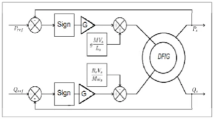
We see in fig.7 the indirect flux orientation strategy with relay standard.
Fig 7:Diagram FOC with relay controller
6.
SIMULATION RESULTS
The system described above is simulated using Matlab - SimulinkTM.
0 0.5 1 1.5 2 2.5 3
-3 -2 -1 0 1 2 3 4 5x 10
4
temps (S)
p
u
is
s
a
n
c
e
r
é
a
c
ti
v
e
(
V
A
r)
Qsref (VAr) Qs(VAr)
Fig 8: Reactive power versus time with PI controller.
0 0.5 1 1.5 2 2.5 3
-2 -1 0 1 2 3 4 5x 10
4
temps (S)
p
u
is
s
a
n
c
e
r
é
a
c
ti
v
e
(
V
A
r)
Qsref (VAr) Qs (VAr)
Fig 9: Reactive power versus time with relay.
0 0.5 1 1.5 2 2.5 3
-2 -1 0 1 2 3 4 5x 10
4
Psref (W) Ps (W)
Fig10: Active power versus time with PI
controller.
0 0.5 1 1.5 2 2.5 3
-3 -2 -1 0 1 2 3x 10
4
temps (S)
p
u
is
s
a
n
c
e
a
c
ti
v
e
(
W
)
Psref (W) Ps (W)
Fig 11: Active power versus time with relay.
0 0.5 1 1.5 2 2.5 3
-150 -100 -50 0 50 100
temps (S)
c
o
u
ra
n
t
ro
to
ri
q
u
e
I
rd
(
A
)
Fig12: Direct current versus time with PI controller.
0 0.5 1 1.5 2 2.5 3
-150 -100 -50 0 50
temps (S)
c
o
u
ra
n
t
ro
to
ri
q
u
e
I
rd
(
A
)
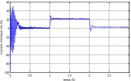
0 0.5 1 1.5 2 2.5 3 -100
-80 -60 -40 -20 0 20 40 60
temps (S)
c
o
u
ra
n
t
ro
to
ri
q
u
e
I
rq
(
A
[image:5.595.70.281.79.209.2])
Fig 14: Squaring current versus time with PI controller.
0 0.5 1 1.5 2 2.5 3
-80 -60 -40 -20 0 20 40 60 80
temps (S)
c
o
u
ra
n
t
ro
to
ri
q
u
e
I
rq
(
A
[image:5.595.71.276.252.384.2])
Fig 15: Squaring current versus time with relay.
We see in fig.8, fig.9, fig.10 and Fig.11 that the corresponding active and reactive powers with PI controller and relay follow the reference signal from 0.21s. We can observe clearly a bigger oscillation and static error in fig.8 and fig.10. Compared with relay have stronger stability and robust. The q-axis component of the rotor current increases to 0.2(A) and remains at that value afterwards while d-axis component of the rotor current remain unchanged (fig.12, fig.13, fig.14 and fig.15) thus show the effectiveness of the proposed control strategy.
7.
CONCLUSION
Stability and robust are the two important performance index of system, especially the stability is the premises of system to work correctly. In order to enhance the stability and robust of yawing system of wind turbine, we design the standard relay
for controlled, set up the simulation model of yawing vector control system, and take simulation research. Compared with PI control and standard relay control, the results of simulation indicate that:
1. whether the change of active power or the change of reactive power, the yawing vector control system with standard relay Synthesis controller have more better stability and robust performance.
2. about the oscillation and static and dynamic error, standard relay Synthesis can make system have more smaller ripple, which is significant for the wind turbine to , reduce the static and dynamic error, the stability and the convergence towards the equilibrium are reached
Appendix
Parameters of the simulated DFIG :
Rs=0,455 Ω ; Rr=0,62 Ω ; Ls=0,084 H ; Lr=0,081 H ;
M= 0.078 H ; J=0.3125 kg.m² ; f=6,73.10-3 N.m.s-1 ;P=2 ;
P=7.5Kw.
NOMENCLATURE
Q
P
,
Stator active and reactive powers.sq
sd
V
V
,
d- and q-axis components of the stator voltage.rq
rd
V
V
,
d-and q -axis components of the rotor voltage.sq sq
i
i
,
d- and q-axis components of the stator current .
rq rd
i
i
,
d- and q-axis components of the rotor current.s
R
Stator phase resistance.
r
R
Rotor phase resistance.sr
M
Mutual inductance between the stator and rotor.r
Rotor pulsation.em
C
Electromagnetic torque.
sq
sd
,
d- and q-axis components of the stator flux linkage.rq
rd
,
d- and q-axis components of the rotor flux linkage.P
Number of poles of the induction machine.s
Stator pulsation.
r
L
Rotor inductance.s
8.
REFERENCES
[1]. M. Verij Kazemi, A. S. Yazdankhah, H. M. Kojabadi,
Direct power control of DFIG based on discrete space vector modulation, Renewable Energy, Vol. 35, pp. 1033- 1042, 2010.
[2]. R. Penaa, R. Cardenasb, E. Escobarb, J. Clarec, P. Wheelerc, Control strategy for a doubly-fed induction generator feeding an unbalanced grid or stand-alone load, Electric Power Systems Research, Vol. 79, pp. 355- 364, 2009.
[3]. guy grellet, guy clerc, actionneurs elctrique (eyrolles, france, 1997).
[4]. M. G. Simões, B. K. Bose, and R. J. Spiegel, “Fuzzy logic based intelligent control of a variable speed cage machine wind generation system,” IEEE Trans. Power Electron., vol. 12, pp. 87–95, Jan. 1997
[5]. Herrera, J.I. and Reddoch, T.W.; “Analysis of The Electrical Characteristics of a Westinghouse Variable Speed Generating System for Wind Turbine Applications”ERI/STR-217-3133, DE88001139, February 1988.
[6].WANG, S.—DING, Y. : Stability Analysis of Field Oriented Doubly Fed Induction Machine Drive Based on Computed Simulation, Electrical Machines and Power
Systems (Taylor & Francis), 1993.Z. Chilengue,
[7]. R. S. Peña, J. C. Clare, and G. M. Asher, “Vector control of a variable speed doubly-fed induction machine for
wind generation systems,” EPEJ., vol. 6, no. 3-4, pp. 60– 67, Dec. 1996.
[8]. POITIERS F. “Etude et Commande de Génératrices Asynchrones pour l’Utilisation de l’Energie Eolienne’’ Thèse de l’Ecole Polytechnique de l’Université de Nantes, Nantes, France, 2003.
[9]. T. Tanaka, T. Toumiya, and T. Suzuki, “Output control by hill-climbing method for a small scale wind power generating system,” Renewable Energy, vol. 12, no. 4, pp. 387–400, 1997.
[10].F. Valenciaga and P. F. Puleston, “Variable structure control of a wind energy conversion system based on a brushless doubly fed reluctance generator,” IEEE Transaction on Energy Conversion, vol. 22, pp. 499– 506, June 2007.
[11]. S. Bhowmik, R. Spee, J. H. R.,Enslin,performance Optimization for Doubly Fed Wind Power generation Systems",IEEE Transactions on Industry Applications, Yol. 35, N" 4, July-August 1999, pp. 949-958.
[12]. K. J. ASTRÖM and T. HÄGGLUND. “Automatic tuning of simple regulators with specifications on phase and amplitude margins”. Automatica, 20(5):645–651 1984.
[13].G. ZIEGLER and N. B. NICHOLS. “Optimum settings for automatic controllers”. Transactions ASME,(64): 759–768, 1942.