Performance Evaluation of Location-Based Geocast Routing using
Directed Flooding Rectangular Forwarding Zone in City VANET
Akhtar Husain
*, S.C. Sharma
Wireless Network Lab, DPT, Indian Institute of Technology, Roorkee, India
Received 02 August 2015; received in revised form 15 September 2015; accepted 24 September 2015
Abstract
Vehicular ad hoc network (VANET) is an application of mobile ad hoc network (MANET) where vehicular
nodes are integrated with GPS and other controlling devices to communicate among each other. Because of
predefined structure of roads as well as very high moving speed of vehicles, routing becomes an extremely
challenging issue in VANET. In literature, authors in research papers related to vehicular communication evaluate
mostly the performance of topology or position-based routing protocols. This article implements a geocast approach
called directed flooding rectangular forwarding zone in distance-effect routing algorithm for mobility (DREAM),
location aided routing (LAR) and zone routing protocol (ZRP) for city vehicular environment. Packet delivery ratio
normalized routing load, delay, throughput, dropped packet ratio and bandwidth wastage parameters are evaluated
using NS-2.33 integrated with IEEE802.11p and IDM_IM based VanetMobiSim. The impact of mobility on these
parameters is also analyzed.
Keywords: VANET, geocast routing, NS-2. 33, VanetMobiSim
1.
Introduction
In vehicular communication, VANET is an interesting application of MANET where a collection of vehicles on the road
for example police vehicle, ambulance, car, bus, truck, cab are used to send urgent message to nearby vehicular nodes and
infrastructural nodes like road-side units (RSUs). It is considered that nodes are integrated with devices for computation, event
recording, transceiver and GPS system. Moving vehicles in VANET make it possible to use safety applications [1] like collision
control warning message, Internet surfing application and advertisement of information. Due to predefined road structures and
layout, vehicles have a constrained mobility path [2] that follows the rules and regulations of the transport department of the
country. In vehicular ad hoc networks, many researchers have studied and compared topology-based routing protocols as
AODV [3], DSR [4] and location based routing protocols like LAR [5] and DREAM [6]. Dedicated Short-Range
Communication (DSRC), an extension of Wi-Fi communication technology, has been proposed for deploying VANETs. IEEE
802.11p [2] is developed and implemented for DSRC particularly designed for wireless communication protocol in VANETs.
The city environment is characterized by vehicle density, restricted vehicular speed, varying speed of vehicles, large
number of road options, shadowing due to obstacles like multi-storey buildings on road sides, number of traffic lights [29-30]
*Corresponding author. E-mail address: [email protected], [email protected]
whereas highway environment is represented by sparse network, very high vehicular speed, road with number of lanes, number
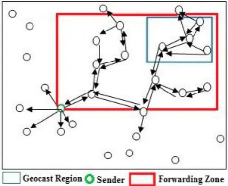
of road segments and one-way traffic [31]. The geocasting [27] is basically a concept derived from location-based multicasting
as shown in Fig. 1, which represents a city scenario based on urban map of tall buildings and intersection of roads. The concept
of geocasting comes to the mind of researchers to send the packets of a message from source node to all the nodes within a
specified geographical region (called Zone of Relevance, ZOR).
Fig. 1 Geocast regions and routing in city VANET
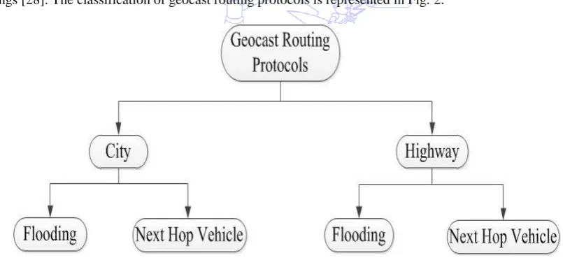
On the basis of traffic types, geocast routing protocols (GRP) are mainly classified in city and highway routing types.
According to message forwarding methods city and highway GRPs has been further divided in flooding and next-hop vehicle
based routings [28]. The classification of geocast routing protocols is represented in Fig. 2.
Fig. 2 Classification of geocast routing
The main interesting objective of geocasting is to guarantee the delivery of valuable information timely and reliably with a
minimum cost. In this article, a geocast approach called directed flooding rectangular forwarding zone has been implemented
in DREAM, LAR and ZRP for city environment taking PDR, normalized routing load, delay, throughput, dropped packet ratio
and bandwidth wastage parameters, and the impact of mobility is also analyzed on these parameters. For obtaining real vehicles
traffic movement traces, an extended version (IDM_IM) of intelligent driver model (IDM) [7] has been used. This paper is
presented in the following sections. Review work has been presented in section 2. Routing protocols DREAM, LAR and ZRP
are described briefly in section 3. Implementation of geocast routing approach called directed flooding rectangular forwarding
zone in DREAM, LAR and ZRP is given in section 4. Simulation setup and parameters are given in section 5. Performance
analyses of the simulated results are presented in section 6. In the end, section 7 gives brief conclusion and further
2.
Review
Routing protocols in VANET applications are broadly classified in two categories, topology- and location-based [8]. Link
information is stored in a table in topology-based, which is used to establish a path from source vehicle to destination vehicle to
transmit packets in the network. Location-based protocols use geographical position of neighboring and destination vehicles to
forward the packets of a message from source to destination vehicle. Authors in [9] have performed the evaluation of GSR,
AODV and DSR protocols. Since GSR is having best features of topology as well as location based routing protocols, it is found
that in the case of PDR and average delay, GSR shows better performance than DSR and AODV. In other article, DSR, TORA,
FSR and AODV in city environment using IDM_IM mobility module of VanetMobiSim traffic simulator are evaluated by
authors in [10] and they have found that AODV outperforms in VANET, and TORA is unsuitable protocol for VANET
scenarios, whereas in [11], authors found that location based protocols are very good in VANET for city as well as highway
scenarios. Authors in [12] performed simulation analysis of DREAM protocol with MOVE [13] and traffic simulator TraNS [14]
and observed that it is good for VANET with average performance. Authors of [15] did simulated analysis of LAR protocol
using IDM and analyzed that LAR is best protocol for VANET since the physical location of the network nodes is already
known with the help of GPS. In [16], authors used a map of JNU campus and routes within the campus to verify the influence of
mobility in vehicular network to analyze AODV protocol using clustering of traffic light at road intersections for smooth
running of the traffic in every direction of the JNU campus. GPSR, AODV and DSR using NS-2 and IDM are evaluated by
authors of [17] and they have concluded that GPSR is better in VANET. In [18], the authors simulated multi-path Doppler
routing protocol (MUDOR), DSR and DSDV, and observed that MUDOR is the best in VANET scenarios. Simulated analysis
has been performed by authors in [19] for position- and topology-based protocols, and it has been observed that position based
routing protocols are better. Authors in [23] performed the analysis of LAR and DREAM routing protocols in VANET using
NS-2 integrated with IEEE802.11p and IDM based VanetMobiSim traffic simulator and found that LAR outperforms than
DREAM protocol in VANET. The authors in traffic light-based time stable geocast (T-TSG) routing for urban VANETs [32]
considered the time to live (TTL) parameter, which varies depending on type of warning.Vehicle Density and Load Aware
(VLDA) Geographic Routing in City Scenarios [33] computes vehicle density and traffic load as network information collection
packet (NICP) in distributed manner. NICP is used to calculate weight for each adjacent road section by junction vehicle.
3.
Various location-based routing protocols in VANET
Greedy perimeter stateless routing(GPSR), geographic source routing (GSR), DREAM, LAR, distance-based routing
protocols (DBR), greedy perimeter coordinator routing (GPCR), anchor-based street and traffic aware routing (A-STAR),
greedy traffic aware routing (Gytar), distance-based routing protocol using location service (DBR-LS) etc. are some examples
of location-based routing protocols for VANET. This article considers DREAM, LAR, ZRP to implement a geocast-based
directed flooding approach.
3.1 Distance-effect routing algorithm for mobility (DREAM)
DREAM [12] protocol forwards the data packets in the network using distance and geographical location of the vehicular
nodes. This geographical location is a very important factor to discover a route from source to destination, and it does the
bounded flooding in a limited expected region. Because DREAM is a proactive routing protocol, each node of the network
stores the location of all the nodes of the network in a table called location table. A control packet is flooded periodically to
update the location of neighbouring nodes. Every location packet generated by a node contains the coordinates of the node
proportional to distance of nodes; therefore, if a node is near to a source node, more location packets are sent to this node. When
a node wants to send a data packet to a node, first of all, it checks its own location table. If the location of destination is found
there, packet of the message is send to one-hop neighbors in the direction of destination; otherwise the protocol starts the route
discovery process.
3.2 Location aided routing (LAR)
To reduce the routing overhead is the main objective of LAR [15] by using position information of the network nodes
which is obtained by a location service (like GPS). Due to known position of the vehicular nodes, broadcasting of the message
is restricted to a small region, which is a request zone to reduce the request packets for route finding. To get the physical location
of target vehicular node, the searching operation of LAR is limited to a limited area, which is called expected zone where
probability for the presence of target node is very large. The use of expected zone reduces the control overhead necessary for
discovery process.
3.3 Zone Routing Protocol (ZRP)
ZRP [24] is a hybrid of proactive and reactive protocols. It is based on the idea of creation of zones in which
communication is possible. For each node, routing zone has been defined that is limited by the transmission range of that node.
The radius of the routing zone is expressed in hops. The zone includes the nodes, whose distance from the particular node is at
most the radius of the zone.
4.
Geocast routing using directed flooding rectangular forwarding zone (GRD flooding RF zone)
The geocast routing protocols have a common objective to send a message to all vehicles within a geographical region.
Location-based routing protocols are based on flooding the forwarding zone only, not the whole network [25-26]. Outside the
forwarding zone, the packet of a message is discarded by the nodes. Directed flooding approach reduces the message overhead
and network congestion incurred in simple flooding with the help of forwarding zone, which is a subset of all vehicular nodes in
the network. The forwarding zone must include at least the sender of a geocast message and the destination region of the
message, and it should also include a path from sender to the destination region. If a path does not exist from source to geocast
region protocols, either the forwarding zone should be increased or the protocol should return to the simple flooding where
message is broadcasted to the whole network.
Authors in [25-26] modify the simple flooding into directed flooding with rectangular forwarding zone where an
intermediate node forwards a packet only if it belongs to the forwarding zone. If the forwarding zone size is increased, then the
probability for reception of a geocast packet at all destination nodes is also increased; however, overhead is also increased. As
in the case of unicast protocol, forwarding zone may be the smallest rectangular region where if we increase destination region
by a factor δ then probability of message reception is also increased. Fig. 3 represents directed flooding with a forwarding zone
whose shape is considered as a rectangle in which every vehicle inside it transmits the packets of the message with broadcasting
approach. If the packets are received by the vehicles moving outside the forwarding zone, these vehicles discard the packet
instead of retransmitting.
4.1 Pseudo code of the GRD flooding RF zone Assumptions and legends:
The coordinates of geographical location of geocast region are (GRx1, GRy1), (GRx2, GRy2), (GRx3, GRy3) and (GRx4, GRy4).
The coordinates of geographical location of rectangular forwarding zone are (RFZx1, RFZy1), (RFZx2, RFZy2), (RFZx3, RFZy3)
and (RFZx4, RFZy4). Coordinates of geographical location of message sender node are (Sx, Sy). Coordinates of geographical
location of intermediate node are (Ix, Iy).
V_ID: Vehicle identification
INFO: Content of message
PRIO: Priority
EV: Emergency vehicle
C_LOC: Current location of the vehicle
C_SPEED: Current speed of the vehicle
C_DIR: Current movement direction of the vehicle
C_ROAD: Current road number
C_LANE: Current lane number of a particular road
LOC_GeoR: Location of the geocast region
LOC_RFZ: Location of rectangular forwarding zone
LOC_NV: Location of the neighbor vehicle
MESSAGE (): Process describing the message
MSG_FORWARD (): Message forwarding process
EV (): Emergency vehicle description process
RECV_DECESION (): Receiver decision process
READ_MSG (): Process to read a message
M_PRIORITY (): Priority assigning process
CHK_PRIORITY (): Vehicle priority check process
The location of all the vehicles is found, and the geocast region is calculated using GPS and stored in a location table of
each vehicle.
Send the message to a neighbour closest to geocast region
MESSAGE (V_ID, INFO, PRIO, C_LOC, C_SPEED, C_DIR, C_ROAD, C_LANE, LOC_NV)
RECCV_DECESION ()
IF a new message arrives then read the message
IF message arrives from more than one vehicle
THEN check the priority of the sender with CHK_PRIORITY () subroutine
IF message sender is in opposite direction then forward the message using MSG_FORWARD ();
IF message sender diverted the route
THEN
Send an alarming message
IF message sender is on the same road THEN check the lane
IF it is on same lane
THEN find the arrival time of the message using EV (C_POS, C_SPEED)
IF lane is different, change the lane using
CHG_LANE ()
ELSE de-accelerate the vehicle
Predict if message sender may be at next intersection then stop own vehicle and let message sender to cross
}
M_PRIORITY ()
{
IF EV=Ambulance THEN set priority =1
IF EV=Fire Vehicle THEN set priority =2
IF EV=Police Vehicle THEN set priority =3
IF EV=General Vehicle THEN set priority =4
}
CHK_PRIORITY ()
{
If more than one message is received at same time
Find high priority and take decision accordingly
}
The above pseudo code describes the directed flooding based geocast routing with rectangular forwarding zone. Every
vehicle maintains its location table and broadcasts periodically its current information, so that the neighbor vehicles could
update their location tables. Due to this periodical broadcast, each and every vehicle has information about the ad hoc network
to which it belongs. Whenever there is an urgent need to inform the vehicles belonging to specified geographical region or
geocast region, the sender vehicle which is outside the forwarding zone searches its location table to find out the path to the
rectangular forwarding zone. If the path is available, it sends the message using MESSAGE () subroutine otherwise path
discovery to forwarding zone is initiated using unicast paradigm with multi-hop strategy. Whenever a vehicle inside the
forwarding zone gets the message, it checks the priority of the sending vehicle by the use of CHK_PRIORITY () subroutine and
using the priority, it floods the forwarding zone with packets of the urgent message using MESSAGE () subroutine which are
received from the sender. If a node outside the forwarding zone receives the packet, it discards it immediately.
The directed flooding concept assumes that the sender of an urgent information and geocast region of the network are
geographically present in the rectangular forwarding zone, and the path is also available from sender to the geocast region.
packets of the urgent message using MESSAGE () subroutine of GRD flooding RF zone algorithm. If there arises a situation
that the route is not available between sender and geocast region, then directed flooding geocast routing protocol increases the
rectangular forwarding zone by changing its dimensions. If it is not possible to increase the forwarding zone due to any problem,
it returns to the simple flooding and floods the whole network with the packets of the urgent message sent by the sender.
4.2 Implementation of geocast directed flooding rectangular forwarding zone in DREAM
(a) Unicast routing (b) Geocast routing with directed flooding
Fig. 4 DREAM with Expected Zone and Network Space[12, 25]
Fig. 4(a) represents the DREAM protocol with expected zone and network space. The sender vehicle is outside the
expected zone in which a single destination vehicle is expected. The sender vehicle S has the position (Xs, Ys) and Destination
vehicle D has the position (Xd, Yd). As shown in Fig. 4(b), the directed flooding is implemented in DREAM protocol by
replacing the single destination expected zone with a geocast region having a group of vehicles. The network space is replaced
with rectangular forwarding zone. In this forwarding zone, there exists a path from sender vehicle to geocast region.
4.3 Implementation of geocast directed flooding rectangular forwarding zone in LAR
(a) Unicast routing (b) Geocast routing with directed flooding
Fig. 5 LAR with request and expected zone[15, 25]
Fig. 5(a) represents the LAR protocol with request zone and expected zone. The implementation of directed flooding with
rectangular forwarding zone in LAR protocol is shown in Fig. 5(b) by replacing the single destination expected zone of LAR
with a geocast region having a group of vehicles. The request zone is replaced with rectangular forwarding zone. The location
4.4 Implementation of geocast directed flooding rectangular forwarding zone in ZRP
(a) Unicast routing (b) Geocast routing with directed flooding
Fig. 6 Zone routing protocol with zone radius [24-25]
Fig. 6(a) represents the ZRP protocol with a zone radius. The sender vehicle S is neighbor of vehicles A, B, C, D and E
which are at one-hop distance. It is obvious that vehicle S can transmit the packet directly to these vehicles because they are in
direct communication range. This one-hop distance is also called zone radius having value equal to 1. The vehicles F, G, H and
I are at zone radius equal to 2 whereas vehicle J is at zone radius equal to 3 from initial source vehicle. The implementation of
directed flooding with rectangular forwarding zone in ZRP protocol is shown in Fig. 6(b) by replacing the zone of ZRP with a
rectangular forwarding zone. A geocast region is implemented in the NS2 code of ZRP so that a group of vehicles can be
considered as destination vehicles.
5.
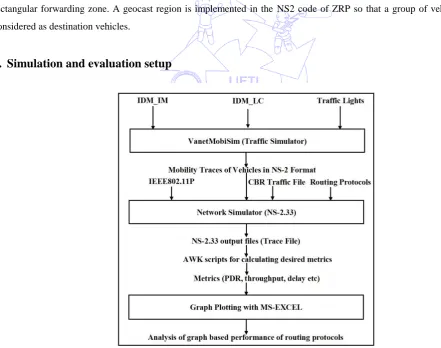
Simulation and evaluation setup
Fig. 7 Simulation setup in VANET
VanetMobiSim is considered the most suitable traffic simulator by researchers due to the integration of components for
road intersection management (IDM_IM), traffic light scheduling and lane changing (IDM_LC). The Simulation setup of
routing protocols in VANET is demonstrated in Fig. 7. For Performance evaluation of DREAM, LAR and ZRP, a network
5.1 System model
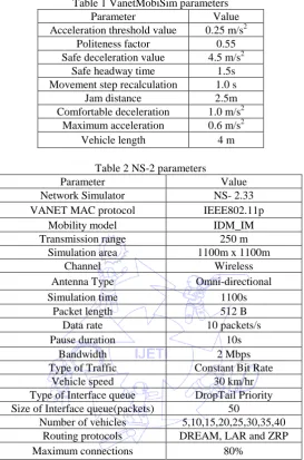
For this paper, mobility model parameters used in VanetMobiSim traffic traces generators have been represented in Table1.
The ns2 parameters used in simulation of routing protocols in VANET have been shown in Table 2.
Table 1 VanetMobiSim parameters
Parameter Value
Acceleration threshold value 0.25 m/s2 Politeness factor 0.55 Safe deceleration value 4.5 m/s2
Safe headway time 1.5s Movement step recalculation 1.0 s
Jam distance 2.5m
Comfortable deceleration 1.0 m/s2 Maximum acceleration 0.6 m/s2
Vehicle length 4 m
Table 2 NS-2 parameters
Parameter Value
Network Simulator NS- 2.33
VANET MAC protocol IEEE802.11p
Mobility model IDM_IM
Transmission range 250 m
Simulation area 1100m x 1100m
Channel Wireless
Antenna Type Omni-directional
Simulation time 1100s
Packet length 512 B
Data rate 10 packets/s
Pause duration 10s
Bandwidth 2 Mbps
Type of Traffic Constant Bit Rate
Vehicle speed 30 km/hr
Type of Interface queue DropTail Priority Size of Interface queue(packets) 50
Number of vehicles 5,10,15,20,25,30,35,40 Routing protocols DREAM, LAR and ZRP
Maximum connections 80%
Results and discussions
Performance evaluation of DREAM, LAR and ZRP protocols with geocast routing using directed flooding rectangular
forwarding zone has been done in this section. Following parameters are considered for simulation:
(1)Packet delivery ratio
(2)Throughput
(3)Delay
(4)Normalized routing load
(5)Dropped packet ratio
(6)Bandwidth wastage
6.1 Packet delivery ratio (PDR)
The packets of the data successfully delivered divided by total packets of the data generated in a network is called PDR.
Mathematically it can be represented as:
PDR= TPD / TPG (1)
where
TPD: Total data packets received successfully
TPG: Total data packets generated
(a) Unicast routing (b) Geocast routing with directed flooding
Fig. 8 Packet delivery ratio in city scenario
Packet delivery ratio is demonstrated in the graph as shown in Fig 8. It is clear from the graph that initially, with the
increase in the number of the nodes PDR also increases. When number of nodes is less, link is not established from source to
destination. As soon as the nodes density increases, the communication link is established and maintained for a long time. Due
to that, routing protocols show good performance as shown in the graph. As the number of nodes is increased further, PDR starts
to drop, since a lot of vehicles access the wireless link. The PDR graph also shows that LAR performs better than DREAM
whereas the performance of ZRP is the lowest. Geocast based DREAM, LAR and ZRP routing protocols as shown in Fig. 8(b)
demonstrates better performance than unicast based protocols as shown in Fig. 8(a).
6.2 Throughput of network
Throughput of the VANET is successfully received packets in terms of Kilo bits per second. Mathematically throughput
can be represented as:
Throughput= SP/TL (2)
where
SP: Total number of packets successfully transmitted
TL: Timestamp recorded in last transmitted packet
(a) Unicast routing (b) Geocast routing with directed flooding
Geocast based DREAM, LAR and ZRP routing protocols as shown in Fig. 9(b) demonstrate better performance than
unicast based protocols as shown in Fig. 9(a). It is evident from the graphs that when node density is up to 15, the throughput is
below 300 kbps, and LAR performs better than DREAM and ZRP. As soon as node density is in the range of 15 to 30, ZRP
shows higher throughput in comparison to DREAM and LAR in city network since the less number of nodes easily establish the
link in the case of ZRP.
6.3 Delay
Delay is the total time taken by the network in memory buffer, waiting in queue, packet retransmission and propagation of
packets. In other words, delay can be represented as the difference of the time stamps between arrival and transmission of the
packets.
(a) Unicast routing (b) Geocast routing with directed flooding
Fig.10 Delay in city scenario
Mathematically delay can be represented as:
Delay = ST / NP (3)
where
ST : Total time taken by the packets to deliver
NP : Total Number of packets received
Geocast-based DREAM, LAR and ZRP routing protocols as shown in Fig. 10(b) represent less delay and demonstrate
better performance than unicast-based protocols as shown in Fig. 10(a). The above graph shows that as the number of nodes is
increased, the delay increases. Up to node density 30, ZRP continuously shows highest delay since the path discovery phase
takes longer. In comparison to ZRP and DREAM, LAR in city scenario depicted less delay. When node densities are 5 to 30
nodes, there is a big difference in delay incurred in LAR and DREAM in comparison to ZRP, whereas as the number of nodes
increases beyond 30, there is a sharp increase in the delay for all the three routing protocols in city scenario and there is very less
difference in the delays of DREAM, LAR and ZRP.
6.4 Normalized Routing Load (NRL)
NRL is equal to the total contribution of the control packets in the network generated for route request, route reply, route
error, route errors retransmission. The ratio of NRL can be calculated by dividing the total control packets transmitted with total
(a) Unicast routing (b) Geocast routing with directed flooding
Fig. 11 Normalized routing load in city scenario
Mathematically NRL can be represented as:
NRL = ST/ SR (4)
where
ST : Total routing packets transmitted
SR : Total data packets received
Graph depicted in Fig. 11 represents normalized routing load (NRL) where highest routing overhead is incurred by ZRP in
comparison to DREAM and ZRP in city scenario. It is observed from the above figure that NRL increases as soon as the
wireless channel is shared by more number of vehicular nodes. LAR showed the lowest overhead in comparison to DREAM and
ZRP. It is evident from the above graph that geocast-based DREAM, LAR and ZRP routing protocols as shown in Fig. 11(b)
demonstrate better performance than unicast-based protocols as shown in Fig. 11(a).
6.5 Drop packet ratio (DPR)
The DPR is the ratio of dropped packets to the packets generated by CBR sources. In other words, DPR is the total number
of the packets lost during communication in the network. Mathematically DPR can be represented as:
Dropped packet ratio (DPR) = SD/ SG (5)
where
SD = Sum of dropped packets by routers
SG = Sum of packets generated by CBR sources
(a) Unicast routing (b) Geocast routing with directed flooding
DPR is depicted by the graph shown in Fig. 12. Initially, DPR is high at less number of nodes. When number of nodes is
increased, more number of nodes can communicate with each other; therefore DPR decreases. As soon as more nodes join the
network to communicate, DPR further increases, due to the fact that now more number of packets are generated and flow in the
network, and there is a competition for sharing the channel, and high number of collisions would be there. ZRP has shown the
highest DPR, while LAR has the lowest DPR. Geocast-based DREAM, LAR and ZRP routing protocols as shown in Fig. 12(b)
indicate lower DPR, which demonstrate better performance than unicast-based protocols as shown in Fig. 12(a).
6.6 Bandwidth wastage (BW)
Bandwidth wastage is the ratio of number of transmission efforts made for dropped packets during the delivery to the total
packets transmitted successfully.
(a) Unicast routing (b) Geocast routing with directed flooding Fig. 13 Bandwidth Wastage in city scenario
Bandwidth wastage (BW) is depicted by the graph shown in Fig. 13. It has been observed that initially BW is high and
decreases with the increasing number of nodes. When number of nodes is increased, it is possible that more number of nodes can
communicate with each other; therefore bandwidth wastage decreases. Comparing Fig. 13(a) and Fig. 13(b), it has been
observed that the implementation of geocast directed flooding lowers the BW in all the three protocols.
6.7 Impact of mobility
There are two situations where mobility places an impact on routing protocols:
(1) If the speed of vehicles increases, the link between source and destination is broken and the transfer of the packets is not
possible. In this situation, PDR and throughput decreases whereas delay, NRL, DPR and bandwidth wastage increases.
(2) If source node finds the location of the destination, it starts to send the packets of the message. But due to mobility, if the
physical location of the destination has changed before arrival of the packet from source, then the source has to reinitiate
the process to establish the connection. In this situation, PDR and throughput of the system will decrease whereas the value
of other parameters will increase which shows lower performance.
6.
Conclusion and further research
Directed flooding based geocast with rectangular forwarding zone approach has been implemented to evaluate the
performance of DREAM, LAR and ZRP location-based protocols in VANET. Network simulator NS-2.33 and traffic simulator
VanetMobiSim are the two simulators used for the analysis of routing protocols in VANET. Every protocol outperforms in
work will be extended to evaluate the location-based geocasting protocols in VANET in highway scenario with next-hop
selection approach and related metrics.
References
[1] X. Yang, J. Liu, N. Vaidya and F.Zhao, “A vehicle-to-vehicle communication protocol for cooperative collision warning,” The IEEE First Annual International Conference on Mobile and Ubiquitous Systems: Networking and Services
(MOBIQUITOUS 04),IEEE press, Aug. 2004, pp. 114-123.
[2] J. Bernsen and D. Manivannan, “Unicast routing protocols for vehicular ad hoc networks: A critical comparison and classification,” Pervasive and Mobile Computing, vol. 5, no.1, pp. 1-18, Feb. 2009.
[3] C.E. Perkins and E. M. Royer, “Ad-hoc on-demand distance vector routing,” Second IEEE Workshop on Mobile
Computing Systems and Applications (WMCSA 99), IEEE press, Feb. 1999, pp. 90-100.
[4] D. B. Johnson and D. A. Maltz, “Dynamic source routing in ad hoc wireless networks,” The Kluwer International Series in Engineering and Computer Science, vol. 353, pp. 90-100, 1996.
[5] T. Camp, J. Boleng, B. Williams, L. Wilcox and W. Navidi, “Performance comparison of two location based routing
protocols for Ad Hoc networks,” Proc. 20th Annual Joint Conference IEEE Computer and Communications Societies (INFOCOM 02), Jun. 2002, vol. 3, pp. 1678-1687.
[6] S. Basagni, I. Chlamtac, V. R. Syrotiuk and B. A. Woodward, “A distance routing effect algorithm for mobility
(DREAM),” Proc. Fourth annual ACM/IEEE international conference on Mobile computing and networking (MobiCom
98), IEEE press, Oct. 1998, pp.76-84.
[7] J. Haerri, F. Filali and C. Bonnet, “Performance comparison of AODV and OLSR in VANETs urban environments under realistic mobility patterns,” Proc. Fifth IFIP Mediterranean Ad-Hoc Networking Workshop, Jun. 2006.
[8] M. Mauve, J. Widmer and H. Hartenstein, “A survey on position-based routing in mobile ad hoc networks,”IEEE Network
Magazine, vol. 15, no.6, pp. 30-39, Aug. 2001.
[9] C. Lochert, H. Hartenstein, J. Tian, H. Fussler , D. Hermann and M. Mauve, “A routing strategy for vehicular ad hoc networks in city environments,” Proc. IEEE Intelligent Vehicles Symposium, IEEE press, pp. 156-161, Jun. 2003. [10] S. Jaap, M. Bechler and L. Wolf, “Evaluation of routing protocols for vehicular ad hoc networks in typical road traffic
scenarios,”Proc. of the Eleventh EUNICE Open European Summer School on Networked Applications, Jul. 2005, pp. 584-602.
[11] A. Husain, B. Kumar and A. Doegar, “Performance evaluation of routing protocols in vehicular ad hoc networks.” International Journal of Internet Protocol Technology, vol. 6, pp. 38-45, Jun. 2011.
[12] M. Bakhouya, J. Gaber and M. Wack, “Performance evaluation of DREAM protocol for inter-vehicle communication,” First International Conference on Wireless Communication, Vehicular Technology, Information Theory and Aerospace & Electronics Systems Technology (Wireless VITAE 09), IEEE press, May 2009, pp. 289-293.
[13] F. K. Karnadi, Z. H. Mo and K. C. Lan, “Rapid generation of realistic mobility models for VANET,” IEEE Wireless
Communications and Networking Conference, IEEE press, Mar. 2007, pp. 2506-2511.
[14] M. Piorkowski, M. Raya, A. L. Lugo, P. Papadimitratos, M. Grossglauser and J. P. Hubaux, “TraNS: Realistic joint traffic and network simulator for VANETs,” ACM SIGMOBILE Mobile Computing and Communications Review, vol. 12, no. 1, pp. 31-33, Jan. 2008.
[15] Y. B. Ko and N. H. Vaidya, “Location -aided routing (LAR) in mobile ad hoc networks,” Wireless Networks, vol. 6, no.4,
pp. 307-321, Sep. 2000.
[16] Nidhi and D. K. Lobiyal, “Performance evaluation of realistic vanet using traffic light scenario,” Int. J. Wireless & Mobile Networks, vol. 4, no.1, pp. 237-249, Feb. 2012.
[17] C. Tee and A. C. Lee, “Survey of position based routing for inter vehicle communication system,” IEEE First International
Conference on Distributed Framework and Applications, IEEE press, Oct. 2008, pp. 174-182.
[18] S. Xi and X. M. Li, “Study of the feasibility of VANET and its routing protocols,” IEEE Fourth International Conference on Wireless Communications, Networking and Mobile Computing, IEEE press, Oct. 2008, pp.1-4.
[19] M. Azarmi, M. Sabaei and H. Pedram, “Adaptive routing protocols for vehicular ad hoc networks,” IEEE International
Symposium on Telecommunications, IEEE press, Aug. 2008, pp. 825-830.
[21] J. Härri, F. Filali, C. Bonnet and M. Fiore, “VanetMobiSim: Generating realistic mobility patterns for VANETs,” Proc. of
the Third International Workshop on Vehicular Ad Hoc Networks, pp. 96-97, Feb. 2006. [22] VanetMobiSim, http://vanet.eurecom.tr, Jul. 2013.
[23] A. Husain, and S. C. Sharma, “Simulated analysis of location and distance based routing in VANET with IEEE802.11p,” Elsevier Third International Conference on Recent Trends in Computing, SRM Uni., Ghaziabad, Procedia Computer
Science, vol. 57, pp. 323-331, Aug. 2015
[24] Z. J. Hass, "The zone routing protocol (ZRP) for Ad Hoc networks," Internet-Draft, http://tools.ietf.org/id/draft-ietf-manet- zone-zrp-04.txt, Jul. 2002
[25] Y. B. Ko and N. H. Vaidya, "Flooding-based geocasting protocols for mobile ad hoc networks," Mobile Networks and
Applications, vol. 7, no.6, pp. 471-480, Dec. 2002.
[26] Y. B. Ko and N. H. Vaidya, "Geocasting in mobile Ad Hoc networks: location based multicast algorithms," Proc. 2nd Wksp. Mobile Compo Sys. and Applications , New Orleans, USA, pp. 101-110, Feb. 1999.
[27] A. Singh and A. K. Verma, “Simulation and analysis of AODV, DSDV, ZRP in VANET,”Int. J. in Foundations of
Computer Science & Technology, vol. 3, no.5, Sep. 2013.
[28] O. Kaiwartya and S. Kumar, "Geocast routing: Recent advances and future challenges in vehicular ad hoc networks," IEEE International Conference on Signal Processing and Integrated Networks (SPIN), Noida, pp. 291-296, Oct. 2014.
[29] R. S. Raw and S. Das, "Performance analysis of P-GEDIR protocol for vehicular ad hoc network in urban traffic
environments," Wireless personal communications, vol. 68, no. 1, pp. 65-78, 2013.
[30] Z. Wang, E. K. Tameh and A. R. Nix, "Joint shadowing process in urban peer-to-peer radio channels," IEEE Transactions on Vehicular Technology, vol. 57, no. 1, pp. 52-64, Sep. 2008.
[31] E. Schoch, F. Kargl, M. Weber and T. Leinmuller, "Communication patterns in VANETs," IEEE Communications
Magazine, vol. 46, no. 11, pp. 119-125, Nov. 2008.
[32] O. Kaiwartya, S. Kumar, R. Kasana, “Traffic light based time stable geocast (T-TSG) routing for urban VANETs,” IEEE Sixth International Conference on Contemporary Computing (IC3), Noida, pp. 113-117, Aug. 2013.
[33] C. Li, C. Zhao, L. Zhu, H. Lin and J. Li, “Geographic routing protocol for vehicular Ad- hoc networks in city scenarios: a
![Fig. 5 LAR with request and expected zone[15, 25]](https://thumb-us.123doks.com/thumbv2/123dok_us/9828193.1968907/7.595.60.527.431.675/fig-lar-request-expected-zone.webp)