HARMONIC SUPPRESSION OF BRANCH-LINE AND RAT-RACE COUPLER USING COMPLEMENTARY SPILT RING RESONATORS (CSRR) CELL
J. Zhang † and X.-W. Sun
Shanghai Institute of Microsystem & Information Technology Chinese Academy of Sciences
Shanghai 200050, China
Abstract—In this paper, complementary spilt ring resonator (CSRR) is applied to design harmonic suppression microstrip rat-race and branch-line coupler. As the CSRR cell is etched on the ground plane of the substrate, the frequency selective properties have a considerable relation with its geometry parameters, which has been analyzed detailedly. As demonstration, a rat-race and a branch-line coupler are designed and fabricated using conventional printed-circuit board fabrication process. The proposed couplers show the performance as good as that of the corresponding conventional structures, but deep harmonic suppression in addition. The design and simulation have been performed using full-wave EM TOOLS ADS Momentum.
1. INTRODUCTION
Split-ring resonators (SRRs) was originally proposed in 1999 [1] by Pendry et al. as basic particles for the design of negative values of permittivity (ε) and permeability (µ). Because of the simultaneous negative values of ε and µ, the wave vector and the electric-and magnetic-field intensity form a left-helectric-anded triplet, with the result of anti-parallel phase and group velocities, or backward-wave propagation, very interesting properties for the design of microwave and millimeter-wave circuits. Split-ring resonators (SRRs) are planar structures with a pair of concentric conducting rings with slits etched on opposite sides. When they are excited by an external time varying
magnetic field applied parallel to the ring axis, an electromotive force around the rings is generated giving rise to current loops in the rings. In contrast to conventional ring resonators, SRRs exhibit a quasi-static resonance by virtue of the distributed capacitance between concentric rings and overall rings inductance.
As the negative image of SRRs, complementary spilt ring res-onators (CSRRs) have been investigated to exhibits an electromagnetic behavior which is almost the dual of that of the SRR [2]. For CSRR based transmission lines, CSRRs must be etched in the ground plane, just underneath the conductor strip, in that region where the electric field is maximal. The dominant driving mechanism for CSRRs excita-tion is electric coupling, the electric field must be applied in the axial direction (magnetic field parallel to ring axis).
A lot of theoretical study of CSRRs has been presented in recent papers [3–8], but all of them either employ electromagnetic field analysis method, or establish equivalent lump circuit model, yet none of them could offer direct synthesis method of distributed microwave circuit using CSRRs. In the paper, the detailed relation between the geometry parameters and electric performance has been studied, which drastically simplifies design procedure and reduce design period. 2. FREQUENCY ELECTIVE PROPERTIES STUDY OF CSRRS
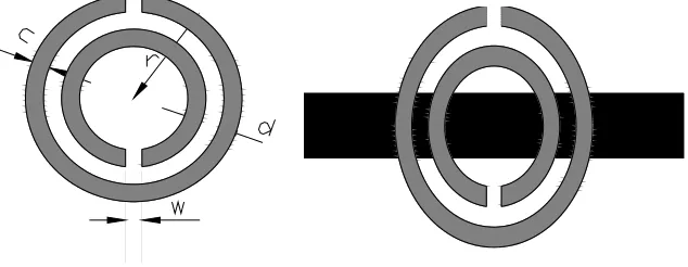
The basic topology of a CSRR is depicted in Fig. 1. This consists of a pair of concentric conducting rings with slits etched on opposite sides. The geometry parameters of the CSRRs (Fig. 1) consist of ring width
c, space between the ringsd, and the ring radiusr and l, which affect the electric performance deeply.
2
L
2
L
C
R
L
C
RR
R
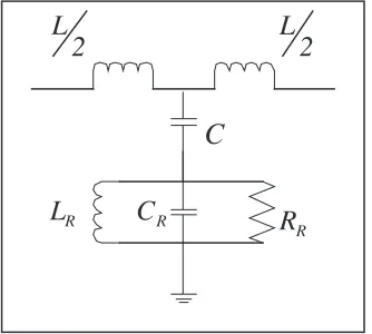
Figure 2. Equivalent lumped parameter circuit of CSRR.
Though the corresponding equivalent lump circuit model of the CSRR has been reported in [9], it has been reproduced here for clarity and completeness.
In the model, L is the line inductance, C is the coupling capacitance between the line and the CSRR. The resonator is described by means of a parallel tank, CR and LR being the reactive elements
and RR accounting for losses, where transmission zero frequency (fZ)
which nulls the shunt impedance is defined as:
fZ =
1
2πLR(CR+C)
(1) Figure 3 shows the simulated transmission zero frequency (fZ) of
four CSRR cell which have different configuration parameters. In the study, the CSRR etched in the ground plane and a microstrip on the surface with the characteristic impedance of 50 Ω line. The simulation is on the substrate ofεr= 2.65, thicknessh= 1000µm and loss tangent
of 0.003. In the simulation, the one parameter was varied while other three were held constant. Evident from the result, the transmission zero frequency (fZ) vary smoothly and appreciably with respect to the
geometry parametersw, c, d, r.
In Fig. 3(a), the dependence of the transmission zero frequency (fZ) upon the ring spilt space w is shown. This is indicative of the
transmission zero frequency (fZ) variations enabled by adjustments the
spilt spacew. The frequencyfZis insensitive to the space size, but the
trend is clear: increasing the spilt space of the ring will introduce the increase of the transmission zero frequency (fZ). An explanation for
100 150 200 250 300 350 400 450 500 6.95 7.00 7.05 7.10 7.15 7.20 7.25 7.30 7.35 7.40
r=1950 m
c=200 µm
d=200 µm
T rans m is sion z ero fz(G Hz)
Spilt space w(µm)
1750 1800 1850 1900 1950 2000 2050 2100 2150 6.0 6.5 7.0 7.5 8.0 8.5
w =300 µm
c=200 µm
d=200 µm
T
ransmission zero f
z
(G
Hz)
R adius r(µm )
100 120 140 160 180 200 220 240 260 6.8 6.9 7.0 7.1 7.2 7.3 7.4 7.5
r=1950 µm
w =300 µm
d=200 µm
T ran sm is s ion z e ro f z (G Hz)
R ing w idth c(µm )
1 0 0 1 2 0 1 4 0 1 6 0 1 8 0 2 0 0 2 2 0 2 4 0 2 6 0 6 .4 6 .6 6 .8 7 .0 7 .2 7 .4 7 .6
w = 3 0 0 µm
c = 2 0 0 µm
r= 1 9 5 0 µm
Transmission
zero
fz(GHz)
R in g s p a c e d (µm )
µ
(a) (b)
(c) (d)
Figure 3. Transmission zero of the microstrip loaded CSRR cell (a) different spilt space (b) different ring radius (c) different ring width (d) different ping space.
flowing around any one ring, which induces the relative decrease in the valueCR.
In Fig. 3(b), one may observe that the transmission zero frequency (fZ) decreases as the ring radius r increases. This has important
implication on the CSRR cell design: the slope offZ depends greatly
upon the radiusr. It can be shown clearly from the Equation (1), the capacitance value CR affects the frequency fZ, while the larger ring
radius corresponding to the larger capacitance.
The dependence of the transmission zero frequency (fZ) upon the
ring widthcis shown in the Fig. 3(c). Noteworthy here is that the ring with larger width has higher transmission zero frequency. This can be explained from the increase of the ring width c induces the decrease of the internal ring radius when the external ring radius r was held constant. In the case, the equivalent area of the capacitor CR was
reduced, which means the increase of thefZ.
with respect to the ring space d. It is clearly that fZ increases with
relative increases in the ring space d. This can be explained from the definition of the capacitanceC= dε, where the decrease of the spaced
induces the increase of the capacitanceCR.
3. DESIGN AND MEASUREMENT
As a demonstration, a branch line coupler and rat-race coupler for 3rd harmonic suppression was designed and fabricated with the common PCB process without via holes and bonding wires. The couplers were designed at the frequency 2.1 GHz, while the spurious pass-band introduced by high orders harmonic occurred at the frequency 6.3 GHz. In the design, the CSRR cells were etched on the ground plane of the substrate (εr = 2.65, h = 1000µm). To succeed in
this aim, the position and broadness of such undesired band should be determined from roughly 6 up to 7 GHz. To efficiently reject this relatively wide band, a set of CSRR cells, tuned at different frequencies within the band, is necessary. The simulated (using Agilent Momentum) frequency responses of the CSRR cell specifically, by setting c = 200µm, d = 200µm, w = 300µm, r = 1800µm is found to be at 6.3 GHz, in the centre of the spurious band. From this geometry, we have slightly scaled up and down CSRRs dimensions in order to obtain multiple closed notches and hence achieve whole band rejection. As depicted in the Fig. 4, CSRR were distributed just along the branches of the couplers to enhance the electric coupling between the line and the cells.
(a) (b)
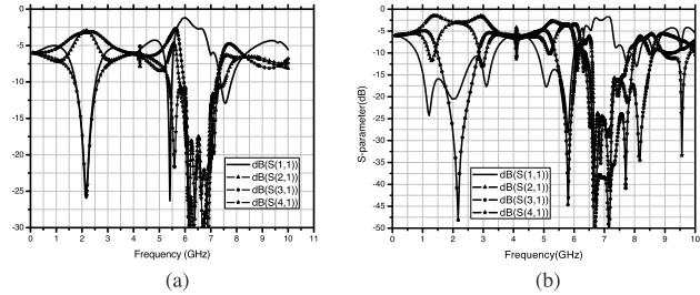
The circuits were measured with Agilent 8510c vector network analyzer. The measured results are shown in the Fig. 5. The measured insertion loss is better than 3.4 dB. It is seen that CSRR couplers has an insertion loss that is comparable to the one with uniform microstrip transmission line. Conventional branch line coupler and rat-race coupler occur periodically at odd harmonics. The proposed couplers operates in the same way as the conventional one, but rejects the 3rd harmonic.
(a) (b)
0 1 2 3 4 5 6 7 8 9 10 11 -30
-25 -20 -15 -10 -5 0
S-p
ara
m
e
ter(
dB)
Frequency (GHz)
dB(S(1,1)) dB(S(2,1)) dB(S(3,1)) dB(S(4,1))
0 1 2 3 4 5 6 7 8 9 10
-50 -45 -40 -35 -30 -25 -20 -15 -10 -5 0
S-parameter(dB)
Frequency(GHz) dB(S(1,1)) dB(S(2,1)) dB(S(3,1)) dB(S(4,1))
Figure 5. (a) Scattering parameters corresponding to the proposed branch-line coupler; (b) Scattering parameters corresponding to the proposed rat-race coupler.
4. CONCLUSION
REFERENCES
1. Pendry, J. B., A. J. Holden, D. J. Robbins, and W. J. Stewart, “Magnetism from conductors and enhanced nonlinear phenom-ena,” IEEE Trans. on MTT, Vol. 47, No. 11, 1999.
2. Falcone, F., T. Lopetegi, J. Baena, R. Marqu´es, F. Mart´ın, and M. Sorolla, “Effective negative-εstopband microstrip lines based on complementary split ring resonators,” IEEE Microwave and Wireless Components Letters, Vol. 14, No. 6, 2004.
3. Burokur, S. N., M. Latrach, and S. Toutain, “Analysis and design of waveguides loaded with split-ring resonators,” Journal of Electromagnetic Waves and Applications, Vol. 19, No. 11, 2005. 4. Xu, W., L. W. Li, H. Y. Yao, T. S. Yeo, and Q. Wu, “Extraction of constitutive relation tensor parameters of SRR structures using transmission line theory,” Journal of Electromagnetic Waves and Applications, Vol. 20, No. 1, 2006.
5. Zhang, J., B. Cui, S. Lin, and X.-W. Sun, “Sharp-rejection low-pass filter with controllable transmission zero using complemen-tary split ring resonators (CSRRs),”Progress In Electromagnetics Research, PIER 69, 219–226, 2007.
6. Zhang, J., B. Cui, J.-Z. Gu, and X.-W. Sun, “Harmonic suppressed wilkinson power divider using complementary split ring resonators (CSRRs),”Journal of Electromagnetic Waves and Applications, Vol. 21, No. 6, 2007.
7. Zhang, X.-C., Z.-Y. Yu, and J. Xu, “Novel band-pass substrate integrated waveguide (SIW) filter based on complementary split ring resonators (CSRRs),”Progress In Electromagnetics Research, PIER 72, 39–46, 2007.
8. Alkanhal, M. and A. F. Sheta, “A novel dual-band reconfigurable square-ring microstrip antenna,” Progress In Electromagnetics Research, PIER 70, 337–349, 2007.