394 |
P a g e
DESIGN OF LOW PASS FIR FILTER USING
HAMMING, BLACKMAN-HARRIS AND TAYLOR
WINDOW
1
Mohd. Shariq Mahoob,
2Rajesh Mehra
1
M.Tech Scholar,
2Associate Professor
1,2
Department of Electronics and Communication Engineering,
National Institute of Technical Teachers’ Training & Research
Chandigarh, UT, (India)
ABSTRACT
Digital filtering plays a significant role in the world of technology. This paper deals with the design of finite impulse response digital filter using window techniques. Here various windows are compared and demonstration of the best window is done, which is the one with minimum side lobes. This is hence the major objective of filtering operation. The experimental results show that the FIR filters designed in this paper are effective for filtering operation. Through this paper the intricacies of the window methods are explained in a simple and a subtle manner.
Keywords:
Blackman-Harris Window, FIR Filter, Hamming Window, MATLAB, Taylor Window.I. INTRODUCTION
Digital signal processing is the technique employed for the mathematical manipulation of an information signal so
as to modify or improve it. For this purpose filters are mainly used. The filter is used to describe a linear time –
invariant system used to perform spectral shaping or frequency-selective filtering. Filter is used in digital signal
processing is widely used in a number of ways, such as removal of undesirable noise from desired signals, spectral
shaping such as equalization of communication channels, signal detection in radar, sonar and communications, and
for performing analysis of the spectra of a variety of signals.[1]
There are two major types of digital filters are:
1) Infinite Impulse response (IIR) filters
2) Finite Impulse response (FIR) filters.
Infinite Impulse Response (IIR) digital filter has the problems of phase non-linearity. Therefore it is a low order
filter which becomes highly unstable. Due to these factors, the FIR filter can be used to design a linear phase digital
filter which is convenient for image processing and data transmission applications. The FIR filters are broadly used
in various fields, such as long distance communication, image processing applications etc
where, L is the length of the filter, and h[n] is the impulse response. [2]
Figure1: Block Diagram of an FIR Filter.
The features of an FIR filter are enumerated below:
1) It is an all zeros filter.
2) It is non-recursive in nature.
3) It does not use feedback.
4) The complexity in implementing is low.
5) It requires higher order of filter for similar specification.
There are various advantages of FIR filter over IIR filter, they are listed as follows:
1) FIR filters are inherently stable.
2) FIR filters have linear phase.[3], [8]
The specification of passband, stop band, and transition band is necessary when designing a frequency-selective
filter. In passband, frequencies are required to be passed unattenuated. In stopband, frequencies needs to be passed
attenuated. Transition band comprises of the frequencies which are lying between the passband and stopband.
Therefore, the whole frequency range is divided into one or even more passbands, stopbands, and transition bands.
FIR filters are less affected by finite word length.
396 |
P a g e
Methods of designing a digital FIR filter:1) Windowing techniques for digital FIR filter design.
2)
Frequency Sampling3) Optimal or Minimax method.[9]
MATLAB software is used to generate the simulation results. The benefit of using this software is that it enables us
to use various tools to make the work easier.
II. WINDOWING TECHNIQUES
The FIR filter design process using window functions can be enumerated as:
1) Define filter specifications.
2) Specify a window function according to the filter specifications.
3) Compute the filter order required for a given set of specifications.
4) Compute the coefficients of the window function to be used.
5) Compute the coefficients the ideal filter according to the filter order.
6) Compute FIR filter coefficients in accordance the obtained window function and the coefficients of the ideal
filter.
7) If the resulting filter has a very wide or a very narrow transition region, it is mandatory to change the filter order
by decreasing or increasing it according to needs, and after this process the steps 4, 5 and 6 are iterated as many
times as needed.
The windows used in this paper to design the FIR filter are:
1) Hamming window
2) Blackman-Harris window
3) Taylor window
The two rudimentary factors that describe a window function are:
1) Width of the main lobe (i.e., at what frequency bin is the power half that of the maximum response)
2) Attenuation of the side lobes (i.e., how far away down are the side lobes from the main lobe). This explains
about the spectral leakage in the window.
III. WINDOWS USED AND THEIR EQUATIONS
Hamming window has a bell-like shape. Its first and last samples are not zero. The window is optimized to minimize
the maximum side lobe. [4].
= 0 ; elsewhere
3.2 Blackman-Harris Window
Blackman-Hariss window is a higher-order generalized cosine window. The Blackman-Hariss windows form a
family of three and four term windows. The variation on the coefficient allows a compromise between main-lobe
width and side-lobe level.
The Blackman-Harris window has one degree of freedom which is used to minimize the level of the side-lobes, and
the other is used for the maximization of the roll-off rate. It defines the three-term Blackman-Harris window as the
one which uses both degrees of freedom to minimize side-lobe level.
= 0 ; elsewhere
3.3 Taylor window
Due to the equiripple condition, the time-domain window has discontinuities at the edges. An approximation that
avoids them, by allowing the equiripples to drop off at the edges, is a Taylor window. This window has a greater
amplitude level. Taylor windows are widely used in radar applications, such as antenna designing.
IV. SIMULATIONS AND RESULTS
Enumerated steps are involved in the simulation of the response:
1) Define total number of sample points (N).
2) Specify the cut-off frequency (wc).
3) Obtain the values of w(n) for the window under consideration.
4) Specify the type of filter and obtain the filter coefficients via passing the defined parameters.
398 |
P a g e
7) Generate the frequency response curve. [3]
The three window functions have been utilized to compute the frequency response of low pass filter and its behavior
is justified by appropriate plots as shown below.
4.1 Hamming window
The low pass filter having order N = 40 is designed. The magnitude and phase response is shown below.
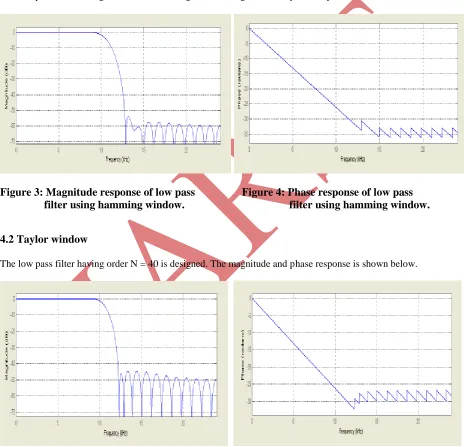
Figure 3: Magnitude response of low pass Figure 4: Phase response of low pass
filter using hamming window. filter using hamming window.
4.2 Taylor window
The low pass filter having order N = 40 is designed. The magnitude and phase response is shown below.
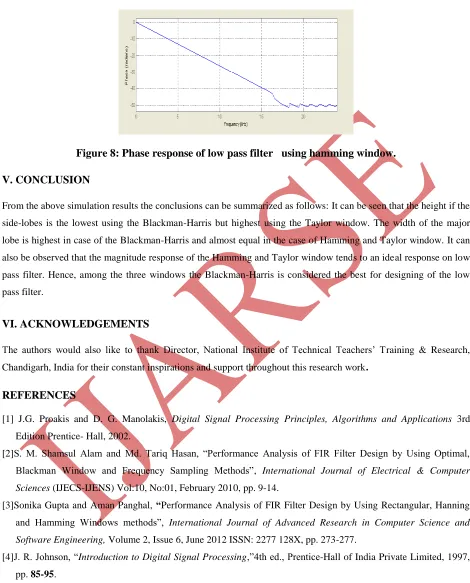
Figure 8: Phase response of low pass filter using hamming window.
V. CONCLUSION
From the above simulation results the conclusions can be summarized as follows: It can be seen that the height if the
side-lobes is the lowest using the Blackman-Harris but highest using the Taylor window. The width of the major
lobe is highest in case of the Blackman-Harris and almost equal in the case of Hamming and Taylor window. It can
also be observed that the magnitude response of the Hamming and Taylor window tends to an ideal response on low
pass filter. Hence, among the three windows the Blackman-Harris is considered the best for designing of the low
pass filter.
VI. ACKNOWLEDGEMENTS
The authors would also like to thank Director, National Institute of Technical Teachers’ Training & Research,
Chandigarh, India for their constant inspirations and support throughout this research work.
REFERENCES
[1] J.G. Proakis and D. G. Manolakis, Digital Signal Processing Principles, Algorithms and Applications 3rd Edition Prentice- Hall, 2002.
[2]S. M. Shamsul Alam and Md. Tariq Hasan, “Performance Analysis of FIR Filter Design by Using Optimal,
Blackman Window and Frequency Sampling Methods”, International Journal of Electrical & Computer
Sciences (IJECS-IJENS) Vol:10, No:01, February 2010, pp. 9-14.
[3]Sonika Gupta and Aman Panghal, “Performance Analysis of FIR Filter Design by Using Rectangular, Hanning
and Hamming Windows methods”, International Journal of Advanced Research in Computer Science and
Software Engineering, Volume 2, Issue 6, June 2012 ISSN: 2277 128X, pp. 273-277.
[4]J. R. Johnson, “Introduction to Digital Signal Processing,”4th ed., Prentice-Hall of India Private Limited, 1997, pp. 85-95.
[5]Tao Zhang, “Research On Design FIR Digital Filter Using MATLAB And Window Function Method”, Journal
400 |
P a g e
[6]Md. Saiful Islam, Md. Shariful Islam, Syed Khalid Rahman, Neelanjana Subin Ferdous and Jakeya SultanaJyoti, “Design of FIR Filter Using Hamming Window”, International Journal of Emerging Research in Management &TechnologyISSN: 2278-9359, 2014 (Volume-3, Issue-2) pp.13-16.
[7]Yadwinder Kumar and Er. Gurpreet Singh Walia “Performance Analysis of FIR Digital High Pass Filters”,
International Journal of Engineering Research and Applications (IJERA) Volume 3, Issue 2, March -April 2013, ISSN: 2248 pp.1012-1015.
[8]Amanjeet Panghal, Nitin Mittal, Devender Pal Singh, R.S. Chauhan and Sandeep K. Arya, “Comparison of
various optimization techniques for design FIR digital filters”, National Conference on Computational Instrumentation, NCCI 2010, 19-20 March 2010, pp.177-181.
[9]Ankan Bhattacharya, “A window function for FIR filter design with an improved frequency response and its
comparison with the Taylor window”, International Journal of Science, Engineering and Technology Research
(IJSETR), Volume 2, Issue 8, August 2013 ISSN: 2278 – 7798, pp.1543-1551.
AUTHORS:
Mohd. Shariq Mahboob received the Bachelors of Technology degree in Electronics and Communication
Engineering from M.J.P.Rohilkhand University Bareilly India in 2008. He is pursuing Masters of
Engineering degree in Electronics and Communication Engineering from National Institute of Technical
Teachers’ Training & Research, Panjab University, Chandigarh, India. He is Lecturer in Electronics and
Communication Engineering Department, United Group of Institutions, Naini, Allahabad. His current
research interests are in Digital Signal Processing and VLSI Design.
Rajesh Mehra received the Bachelors of Technology degree in Electronics and Communication Engineering from National Institute of Technology, Jalandhar, India in 1994, and the Masters of
Engineering degree in Electronics and Communication Engineering from National Institute of Technical
Teachers’ Training & Research, Panjab Univsrsity, Chandigarh, India in 2008. He is pursuing Doctor of
Philosophy degree in Electronics and Communication Engineering from National Institute of Technical
Teachers’ Training & Research, Panjab Univsrsity, Chandigarh, India.
He is an Associate Professor with the Department of Electronics & Communication Engineering,, National Institute of Technical Teachers’ Training & Research, Ministry of Human Resource Development, Chandigarh, India. His current research and
teaching interests are in Signal, and Communications Processing, Very Large Scale Integration Design. He has authored more