GENERAL GUIDELINES FOR APPLICATION OF THE EXTENDED
SUBTRACTION METHOD IN SASSI SOIL-STRUCTURE INTERACTION
ANALYSIS
C. C. Chin1, Nan Deng2, and Farhang Ostadan3
1
Senior Engineer, Bechtel Corporation, San Francisco, CA ([email protected])
2
Engineering Supervisor, Bechtel Corporation, San Francisco, CA
3
Bechtel Fellow, Chief Engineer, Bechtel Corporation, San Francisco, CA
ABSTRACT
The computer program SASSI (1999) is widely used for seismic soil-structure interaction (SSI) analysis of nuclear structures. The program offers two main sub-structuring methods: the Direct method and the Subtraction method. These methods are the basis for computation of the impedance matrix as well as formulation of the equation of motion for typical SASSI SSI models. The difference between the two methods is in the size of impedance problem which is defined by the number of interaction nodes in the free-filed sub-structure model from which the flexibility matrix and subsequently the impedance matrix is computed frequency by frequency. The Direct method, developed in early 1980s as part of the original SASSI program imposes the displacement compatibility between the free-field substructure and the entire excavated soil volume through the common interaction nodes of the two substructures thus the method requires a large group of interaction nodes. However, the strict requirement of the displacement compatibility between the two substructures does make the Direct method capable of producing stable and accurate results within the range of frequencies limited by mesh sizes.
In the Subtraction method, the compatibility of the displacement is maintained for a smaller set of interaction nodes at the common boundary of the free-field substructure and the excavated soil. The limitation of the Subtraction method associated with maintaining the compatibility of the displacement at limited number of interaction nodes must be recognized and considered in the modeling and analysis. The accuracy of the solution by the Subtraction method can be improved significantly by extending the Subtraction method to so called “Extended Subtraction” method (ESM). The Extended Subtraction method is based on the experience of SSI analysis for several verification examples that can in effect re-produce the solution of the Direct method with substantially reduced computational effort.
INTRODUCTION
displacement compatibility between the two substructures does make the Direct method capable of producing stable and accurate results within the range of frequencies limited by mesh sizes.
In the Subtraction method, the compatibility of the displacement is maintained for a smaller set of interaction nodes at the common boundary of the free-field substructure and the excavated soil. The Subtraction method significantly reduces the numerical effort involved in calculation of the impedance matrix for largely embedded structures but suffers from numerical accuracy at high frequencies of the SSI analysis. The accuracy of the solution by the Subtraction method can be improved significantly by extending the Subtraction method to so called “Extended Subtraction” method (ESM). The Extended Subtraction method is based on the experience of SSI analysis for several verification examples that can in effect re-produce the solution by the Direct method with substantially reduced computational effort. The Extended Subtraction method starts by imposing the compatibility of the displacement at the surface of the free-field site as interaction nodes. For deeply embedded structures, additional horizontal layers of interaction nodes may be necessary to ensure stable and accurate results.
SCATTERING RESPONSES
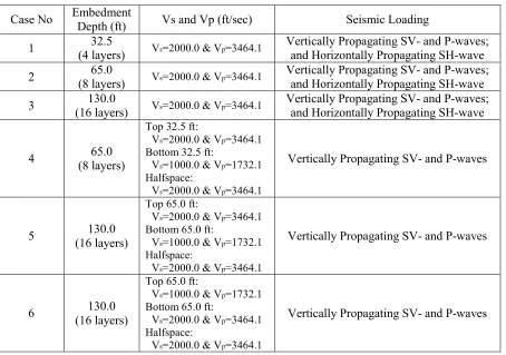
In this paper, scattering responses of embedded rigid massless cylinders subjected to vertically propagating SV- and P-waves and horizontally propagating SH-wave are computed. Parts of the SV- and SH-wave results of analysis are compared with the solution published by Day (1977). Six cases of SASSI models representing embedded foundations with a dimensionless parameter H of 0.5, 1.0, and 2.0 are analyzed. The parameter, H, is defined as the ratio of the embedment depth to the radius of the foundation. The SASSI soil layer models consist of 4 (Case 1), 8 (Cases 2 and 4), and 16 (Cases 3, 5, and 6) top layers and a halfspace below the top layers. Each of the top layers has a thickness of 8.125 ft. The halfspace is modeled by an additional 10 layers with varying thicknesses as a function of frequency and a viscous boundary at the base. The shear-wave velocity (Vs) and P-wave velocity (Vp) of the soil layers for the six cases are summarized in Table 1. Other soil properties used are: weight density= 128.68 pcf, Poisson's ratio= 0.25, and material damping= 0.01.
It is noted that the halfspace in all cases has the same shear-wave (Vs=2000 ft/sec) and P-wave velocity (Vp= 3464.1 ft/sec). The foundations are rigid massless cylinders with a radius (R) of 65
ft and are fully embedded to a depth of 32.5 (Case 1, H=0.5), 65 (Cases 2 and 4), and 130 (Cases 3, 5, and 6, H=2.0) ft. Stiff properties are used to ensure the rigidness of the foundation.
MODELING
Excavated Soil and Structural Models
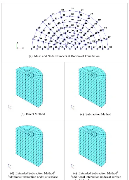
Half of the cylinder foundations are modeled due to symmetry and discretized using brick elements. Nodes at the bottom of the foundation models are the same for all cases (H=0.5, 1.0, and 2.0) as shown in Figure 1(a). The excavated soil models are created similarly to the cylinder foundation models. The finite element models of the excavated soil for the various sub-structure methods in the cases of H=2.0 are also shown Figure 1. It is noted that the symbol, *, is used to indicate interaction nodes in these figures. For example, all nodes of the excavated soil models in the Direct method are interaction nodes as shown in Figure 1(b).
SSI Frequencies and Wave Fields
(a) Mesh and Node Numbers at Bottom of Foundation
(b) Direct Method (c) Subtraction Method
(d) Extended Subtraction Method1
1
additional interaction nodes at surface
(e) Extended Subtraction Method2
2
additional interaction nodes at surface and mid-depth
Note: *’s are interaction nodes.
Vs R f 2
a0 =
π
⋅ ⋅ (1)where R is the radius of the cylinder and Vs is the shear wave velocity of the soil material. It is noted that the a0 is only applicable to Cases 1, 2, and 3 because of the uniform Vs in these cases. Also it is noted that
the model mesh constructed for this problem is valid up to the frequency limit of 33.3 Hz corresponding to a0 = 6.8 for the three cases. The model mesh is valid up to the frequency limit of 16.7 Hz for Cases 4,
5, and 6.
The control motion is specified to be vertically propagating SV- or P-wave; or horizontally propagating SH-wave with a control point defined at the ground surface.
Table 1: Tables should be centered and preceded by a numbered caption.
Case No Embedment
Depth (ft) Vs and Vp (ft/sec) Seismic Loading
1 32.5
(4 layers) Vs=2000.0 & Vp=3464.1
Vertically Propagating SV- and P-waves; and Horizontally Propagating SH-wave
2 65.0
(8 layers) Vs=2000.0 & Vp=3464.1
Vertically Propagating SV- and P-waves; and Horizontally Propagating SH-wave
3 130.0
(16 layers) Vs=2000.0 & Vp=3464.1
Vertically Propagating SV- and P-waves; and Horizontally Propagating SH-wave
4 65.0 (8 layers)
Top 32.5 ft:
Vs=2000.0 & Vp=3464.1 Bottom 32.5 ft:
Vs=1000.0 & Vp=1732.1 Halfspace:
Vs=2000.0 & Vp=3464.1
Vertically Propagating SV- and P-waves
5 130.0 (16 layers)
Top 65.0 ft:
Vs=2000.0 & Vp=3464.1 Bottom 65.0 ft:
Vs=1000.0 & Vp=1732.1 Halfspace:
Vs=2000.0 & Vp=3464.1
Vertically Propagating SV- and P-waves
6 130.0 (16 layers)
Top 65.0 ft:
Vs=1000.0 & Vp=1732.1 Bottom 65.0 ft:
Vs=2000.0 & Vp=3464.1 Halfspace:
Vs=2000.0 & Vp=3464.1
Vertically Propagating SV- and P-waves
ANALYSIS RESULTS
SV- and SH-Wave Scattering Response of Cases 1, 2, and 3
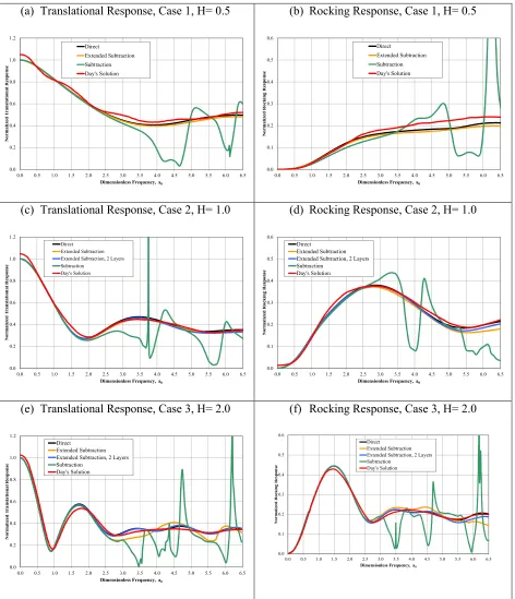
It is noted that the Extended Subtraction method with two additional layers of interaction nodes at the ground surface and at the mid-depth of the foundations are only analyzed for Cases 2 and 3 because the embedment of the foundation in Case 1 is shallow. The amplitude of the translational response motion at Node 1 (X-direction, see Figure 1(a) for locations of nodes) and the amplitude of the rocking motion (Z-direction at Node 66, assuming that the vertical response at Node 1 is negligible) of the foundation subjected to vertically propagating SV-waves for the three cases are normalized to the amplitude of free-field motion and plotted in Figure 2. The results are compared with results reported by Day (1977). As shown in the figure, the results by the Direct method and Extended Subtraction method with two additional layers of interaction nodes (at the ground surface and at the mid-depth of the embedment) and the results reported by Day are in good agreement in all cases. The accuracy of the results by the Extended Subtraction method (additional interaction nodes at the ground surface) are in agreement with Day’s solutions below a0=5 in Case 3 (H=2.0). The Subtraction method is most efficient and the results
are accurate when a0 is less than 3 in all cases.
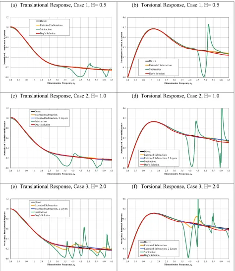
The horizontal responses of foundation to horizontally propagating SH-wave are shown in terms of the response at Node 1 (Y-direction) and compared with the results reported by Day in Figure 3 for Cases 1, 2 and 3. In addition to the horizontal response motion, SH-waves create some torsional response motion in the foundation. The torsional response is presented by X-direction response at Node 72 (see Figure 1(a) for locations of nodes), assuming that X-direction response at Node 1 is negligible. The results are normalized to the unit amplitude of control motion at the free-field surface and plotted in Figure 3. The results by the Direct method and Extended Subtraction method with two additional layers of interaction nodes (at the ground surface and at the mid-depth of the embedment) and the results reported by Day are in good agreement in all horizontally propagating SH-wave cases. The accuracy of the results by the Extended Subtraction method (additional interaction nodes at the ground surface) reduces above a0=3 in Case 3 (H=2.0) and the rest of the results are in good agreement with Day’s results.
As in the vertically propagating SV-wave loading, the Subtraction method is accurate when a0 is less than
3 for the horizontally propagating SH-wave loading.
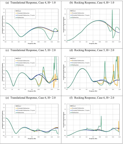
SV-Wave Scattering Response of Cases 4, 5, and 6
(a) Translational Response, Case 1, H= 0.5 0.0 0.2 0.4 0.6 0.8 1.0 1.2
0.0 0.5 1.0 1.5 2.0 2.5 3.0 3.5 4.0 4.5 5.0 5.5 6.0 6.5
N o rm a li ze d T ra n sl a ti o n a l R es p o n se
Dimensionless Frequency, a0 Direct
Extended Subtraction Subtraction Day's Solution
(b) Rocking Response, Case 1, H= 0.5
0.0 0.1 0.2 0.3 0.4 0.5 0.6
0.0 0.5 1.0 1.5 2.0 2.5 3.0 3.5 4.0 4.5 5.0 5.5 6.0 6.5
N o rm a li ze d R o ck in g R es p o n se
Dimensionless Frequency, a0 Direct Extended Subtraction Subtraction Day's Solution
(c) Translational Response, Case 2, H= 1.0
0.0 0.2 0.4 0.6 0.8 1.0 1.2
0.0 0.5 1.0 1.5 2.0 2.5 3.0 3.5 4.0 4.5 5.0 5.5 6.0 6.5
N o rm a li ze d T ra n sl a ti o n a l R es p o n se
Dimensionless Frequency, a0 Direct
Extended Subtraction Extended Subtraction, 2 Layers Subtraction
Day's Solution
(d) Rocking Response, Case 2, H= 1.0
0.0 0.1 0.2 0.3 0.4 0.5 0.6
0.0 0.5 1.0 1.5 2.0 2.5 3.0 3.5 4.0 4.5 5.0 5.5 6.0 6.5
N o rm a li ze d R o ck in g R es p o n se
Dimensionless Frequency, a0 Direct
Extended Subtraction Extended Subtraction, 2 Layers Subtraction
Day's Solution
(e) Translational Response, Case 3, H= 2.0
0.0 0.2 0.4 0.6 0.8 1.0 1.2
0.0 0.5 1.0 1.5 2.0 2.5 3.0 3.5 4.0 4.5 5.0 5.5 6.0 6.5
N o rm a li ze d T ra n sl a ti o n a l R es p o n se
Dimensionless Frequency, a0 Direct
Extended Subtraction Extended Subtraction, 2 Layers Subtraction
Day's Solution
(f) Rocking Response, Case 3, H= 2.0
0.0 0.1 0.2 0.3 0.4 0.5 0.6
0.0 0.5 1.0 1.5 2.0 2.5 3.0 3.5 4.0 4.5 5.0 5.5 6.0 6.5
N o r m a li z ed R o c k in g R e sp o n se
Dimensionless Frequency, a0 Direct Extended Subtraction Extended Subtraction, 2 Layers Subtraction
Day's Solution
(a) Translational Response, Case 1, H= 0.5 0.0 0.2 0.4 0.6 0.8 1.0 1.2
0.0 0.5 1.0 1.5 2.0 2.5 3.0 3.5 4.0 4.5 5.0 5.5 6.0 6.5
N o rm a li ze d T ra n sl a ti o n a l R es p o n se
Dimensionless Frequency, a0 Direct
Extended Subtraction Subtraction Day's Solution
(b) Torsional Response, Case 1, H= 0.5
0.0 0.1 0.2 0.3 0.4 0.5 0.6
0.0 0.5 1.0 1.5 2.0 2.5 3.0 3.5 4.0 4.5 5.0 5.5 6.0 6.5
N o rm a li ze d T o rsi o n a l R esp o n se
Dimensionless Frequency, a0 Direct
Extended Subtraction Subtraction Day's Solution
(c) Translational Response, Case 2, H= 1.0
0.0 0.2 0.4 0.6 0.8 1.0 1.2
0.0 0.5 1.0 1.5 2.0 2.5 3.0 3.5 4.0 4.5 5.0 5.5 6.0 6.5
N o rm a li ze d T ra n sl a ti o n a l R es p o n se
Dimensionless Frequency, a0 Direct
Extended Subtraction Extended Subtraction, 2 Layers Subtraction
Day's Solution
(d) Torsional Response, Case 2, H= 1.0
0.0 0.1 0.2 0.3 0.4 0.5 0.6
0.0 0.5 1.0 1.5 2.0 2.5 3.0 3.5 4.0 4.5 5.0 5.5 6.0 6.5
N o rm a li ze d T o rs io n a l R es p o n se
Dimensionless Frequency, a0 Direct
Extended Subtraction Extended Subtraction, 2 Layers Subtraction
Day's Solution
(e) Translational Response, Case 3, H= 2.0
0.0 0.2 0.4 0.6 0.8 1.0 1.2
0.0 0.5 1.0 1.5 2.0 2.5 3.0 3.5 4.0 4.5 5.0 5.5 6.0 6.5
N o rm a li ze d T ra n sl a ti o n a l R es p o n se
Dimensionless Frequency, a0 Direct
Extended Subtraction Extended Subtraction, 2 Layers Subtraction
Day's Solution
(f) Torsional Response, Case 3, H= 2.0
0.0 0.1 0.2 0.3 0.4 0.5 0.6
0.0 0.5 1.0 1.5 2.0 2.5 3.0 3.5 4.0 4.5 5.0 5.5 6.0 6.5
N o rm a li ze d T o rs io n a l R es p o n se
Dimensionless Frequency, a0 Direct
Extended Subtraction Extended Subtraction, 2 Layers Subtraction
Day's Solution
(a) Translational Response, Case 4, H= 1.0 0.0 0.2 0.4 0.6 0.8 1.0 1.2 1.4 1.6 1.8
0.0 2.0 4.0 6.0 8.0 10.0 12.0 14.0 16.0
N o rm a li ze d T ra n sl a ti o n a l R es p o n se Frequency (Hz) Direct Extended Subtraction Extended Subtraction, 2 Layers Subtraction
(b) Rocking Response, Case 4, H= 1.0
0.0 0.2 0.4 0.6 0.8 1.0 1.2
0.0 2.0 4.0 6.0 8.0 10.0 12.0 14.0 16.0
N o rm a li ze d R o ck in g R es p o n se Frequency (Hz) Direct Extended Subtraction Extended Subtraction, 2 Layers Subtraction
(c) Translational Response, Case 5, H= 2.0
0.0 0.2 0.4 0.6 0.8 1.0 1.2 1.4 1.6 1.8
0.0 2.0 4.0 6.0 8.0 10.0 12.0 14.0 16.0
N o rm a li ze d T ra n sl a ti o n a l R es p o n se Frequency (Hz) Direct Extended Subtraction Extended Subtraction, 2 Layers Subtraction
(d) Rocking Response, Case 5, H= 2.0
0.0 0.2 0.4 0.6 0.8 1.0 1.2
0.0 2.0 4.0 6.0 8.0 10.0 12.0 14.0 16.0
N o rm a li ze d R o ck in g R es p o n se Frequency (Hz) Direct Extended Subtraction Extended Subtraction, 2 Layers Subtraction
(e) Translational Response, Case 6, H= 2.0
0.0 0.2 0.4 0.6 0.8 1.0 1.2 1.4 1.6 1.8
0.0 2.0 4.0 6.0 8.0 10.0 12.0 14.0 16.0
N o rm a li ze d T ra n sl a ti o n a l R es p o n se Frequency (Hz) Direct Extended Subtraction Extended Subtraction, 2 Layers Subtraction
(f) Rocking Response, Case 6, H= 2.0
0.0 0.2 0.4 0.6 0.8 1.0 1.2
0.0 2.0 4.0 6.0 8.0 10.0 12.0 14.0 16.0
N o rm a li ze d R o ck in g R es p o n se Frequency (Hz) Direct Extended Subtraction Extended Subtraction, 2 Layers Subtraction
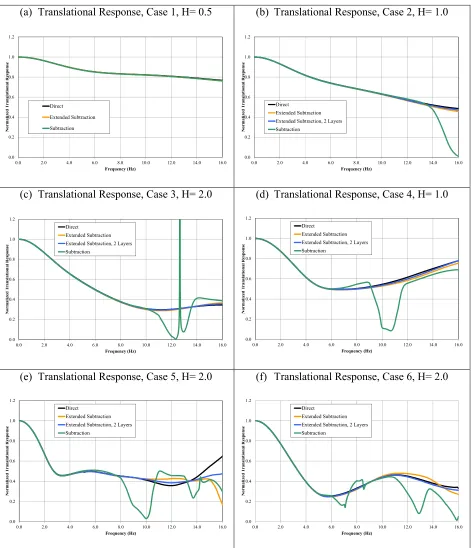
P-wave Scattering Response of All Cases
(a) Translational Response, Case 1, H= 0.5 0.0 0.2 0.4 0.6 0.8 1.0 1.2
0.0 2.0 4.0 6.0 8.0 10.0 12.0 14.0 16.0
N o rm a li ze d T ra n sl a ti o n a l R es p o n se Frequency (Hz) Direct Extended Subtraction Subtraction
(b) Translational Response, Case 2, H= 1.0
0.0 0.2 0.4 0.6 0.8 1.0 1.2
0.0 2.0 4.0 6.0 8.0 10.0 12.0 14.0 16.0
N o rm a li ze d T ra n sl a ti o n a l R es p o n se Frequency (Hz) Direct Extended Subtraction Extended Subtraction, 2 Layers Subtraction
(c) Translational Response, Case 3, H= 2.0
0.0 0.2 0.4 0.6 0.8 1.0 1.2
0.0 2.0 4.0 6.0 8.0 10.0 12.0 14.0 16.0
N o rm a li ze d T ra n sl a ti o n a l R es p o n se Frequency (Hz) Direct Extended Subtraction Extended Subtraction, 2 Layers Subtraction
(d) Translational Response, Case 4, H= 1.0
0.0 0.2 0.4 0.6 0.8 1.0 1.2
0.0 2.0 4.0 6.0 8.0 10.0 12.0 14.0 16.0
N o rm a li ze d T ra n sl a ti o n a l R es p o n se Frequency (Hz) Direct Extended Subtraction Extended Subtraction, 2 Layers Subtraction
(e) Translational Response, Case 5, H= 2.0
0.0 0.2 0.4 0.6 0.8 1.0 1.2
0.0 2.0 4.0 6.0 8.0 10.0 12.0 14.0 16.0
N o rm a li ze d T ra n sl a ti o n a l R es p o n se Frequency (Hz) Direct Extended Subtraction Extended Subtraction, 2 Layers Subtraction
(f) Translational Response, Case 6, H= 2.0
0.0 0.2 0.4 0.6 0.8 1.0 1.2
0.0 2.0 4.0 6.0 8.0 10.0 12.0 14.0 16.0
N o rm a li ze d T ra n sl a ti o n a l R es p o n se Frequency (Hz) Direct Extended Subtraction Extended Subtraction, 2 Layers Subtraction
CONCLUSION
The Extended Subtraction method is an extension of the Subtraction method based on the experience of soil-structure interaction (SSI) analysis for several verification examples and nuclear power plant structures that can in effect re-produce the solution by the Direct method with substantially reduced computational effort. For most cases in which the ratio of the embedment depth to the radius of the foundation is less than 2 (H<2), the Extended subtraction method (additional interaction nodes at the ground surface) efficiently produces stable and accurate results. For deeply embedded foundations (H≥2), it is recommended that additional layers of interaction nodes should be considered between the ground surface and the bottom of the foundations.
REFERENCES
University of California at Berkeley (1999). “SASSI2000 - A System for Analysis of Soil-Structure Interaction.”