Fast Tracking MPPT for Photo Voltaic System
Using ANFIS Control Logic Algorithm
Mekapati Suresh Reddy1, Prof.P.V.Ramana Rao2
P.G. Student, Department of Electrical Engineering, Acharya Nagarjuna University, Guntur, Andhrapradesh, India1
Professor, Department of Electrical Engineering, Acharya Nagarjuna University, Guntur, Andhrapradesh, India2
ABSTRACT: The main theme of this research is to design and implementation of the MPPT with fuzzy logic & ANFIS control algorithm. Fuzzy logic and ANFIS naturally deals with nonlinearities. This technique overcomes the difficulty in the modelling of the nonlinear systems. In order to accomplish this aim, an SPS model consists of a PV module, a dc-dc converter, and a fuzzy logic controller & ANFIS was developed. An integrated model of the PV module and the identified converter was simulated and the results used to derive the expert knowledge needed to formulate and tune the fuzzy logic controller & ANFIS. The proposed method shows better performance in the mpp and tracking speed to parameter variation. The results represents that a significant amount of additional energy can be extracted from a photovoltaic module by using a fuzzy logic & ANFIS based maximum Power Point tracker.
KEYWORDS: PV system; mpp; SPS; MPPT; Fuzzy; ANFIS; P &O.
I. INTRODUCTION
Energy neither be created nor be destroyed but it can be transformed from one form to other form only which supports the Newton’s law of conversation of energy. Energy can be available in the form of two types of sources, one form of Renewable energy sources includes Solar energy, Wind energy, Geothermal energy, Tidal energy, Hydro energy etc. are inexhaustible in nature, Other form of source is non-renewable energy includes thermal, diesel, gas, nuclear are generally called as a conventional energy sources. Big challenge to the electrical engineer is to generate the power continuously to meet the demand without failing. The availability of conventional energy sources are going to exhaustible. We have to depend on other alternative sources which are in inexhaustible form. Solar energy the prime energy sources which are being utilized in this regard. The continuous usage of fossil fuels affects the depletion of the biosphere which leads to global warming.
Sun is the main source of solar energy and delivers 1.6x10^18 units of energy annually on to the earth. This is 20,000 times the requirement of mankind on the earth. 0.1% of solar energy converted in to electrical energy at an efficiency of 10% would world generating capacity of about 3000GW be 4 times the solar energy. Solar energy can be useful for many purposes which are evaporation of water leading to rains, creation of rivers, and photosynthesis for plants and finally negligible small fraction of energy can be used for conversion of energy to electrical energy.
Photovoltaic system consists of number of solar cells to produce desirable amount of power. Single solar cell alone can generates the power of 1-2watt [1] which is not sufficient to use the power at load at high levels, in order to produce more amount of power we need to connect more amount of Solar cells in series and parallel combination called PV modules. PV modules connected in parallel and series to form PV array. The PV solar cell is modelled by using two diode models [2]. Two diode models shows better results under low illumination level, the form factor is the size, configuration, or physical arrangement of a computing device.
Maximum power point (MPP) without having particular control logic in the MPPT boost converter. If the MPP is not Tracked continuously by the proper controller, there will be Power losses in the system which leads to discontinuity of the output voltage of the Solar system doesn’t boost up to the desired value [3]. The voltage at the output side of the PV system is quite low as compared with the required rating level. This output voltage can bringing up to required rating value of 220V by using Boost converter with proper control logic.
The control logic for the MPPT boost converter can be selected on the basis of simplicity and ease implementation of the P&O algorithm. AI based techniques offers high accurate and flexible nature towards the nonlinear nature of the photovoltaic system.AI techniques gives fast & computationally demanding solution for the nonlinear Photovoltaic system problems.
Fuzzy logic is simple to design as it doesn’t require knowledge of the exact model but requires the operation information of the model. In this paper Fuzzy logic based MPPT and ANFIS based MPPT will replaces the P&O based MPPT controller in the SPS. A comparative analysis for the different MPPT control logic performances in the SPS are to be implemented and examined in this paper. In the following sections solar power system modelling with MPPT controlled boost converter can be discussed in detail.
.
II. MODELLINGOFPHOTOVOLTAICMODULESINMATLAB,SIMULINK
Solar power system consists of three stages: the generation side stage, converter /controller side stage and the load side stage. The proposed designed model consists of PV panel, dc/dc boost converter and MPPT controller using P&O, Fuzzy and ANFIS algorithms. The designed and proposed diagram of the model is as shown in Fig.1
Fig.1. Block Diagram of Solar Power System
Normal PV cell mathematical analysed models were proposed by Different researchers in [4-5]. Simulation is needed to get the real significance of a mathematical model of a two-diode model of a PV cell and as shown in Fig. 2. The performance of a two diode model under the low illumination level is better over the single diode model [6].
Fig.2. Equivalent circuit of two-diode model of PV cell
The relation between the output current (I) and output voltage (V) can be calculated by applying Kirchhoff’s current law (KCL) to the above figure 2 [7].
Where
Iph = Photo-generated current ID1 = current in the diode 1 ID2 = current in the diode 2 Rs = Series Resistance, Rp = Shunt Resistance, V = output voltage, I=Ipv = PV current.
1 = 1 exp ∗
1∗ ∗ −1 − − − − −(2) 2 = 02 exp ∗
2∗ ∗ −1 − − − − −(3)
Where, Io1, Io2 are the reverse saturation currents of individual diodes D1& D2, q is the charge of electron (1.602∗
10 c) , N1, N2 are the quality factors of individual diodes D1& D2, k is the Boltzmann constant (1.38∗10 )
and T is the junction temperature. Rewriting the 2 and 3 equations as
1 = 1 exp + ∗
1∗ −1 − − − − −(4) 1 = 1 exp + ∗
2∗ −1 − − − − −(5)
Where = ∗ ∗ = Thermal voltage of the PV panel Ns = Number of cells connected in series
ℎ= ∗ − − − − −(6) Substituting equations 4,5and 6 in equation 1 we get
= ℎ − 1 exp + ∗
1∗ −1 − 02 exp
∗
2∗ ∗ −1 −
+ ∗
− − − − −(7)
A two-diode model implemented in MATLAB Simulink for analyzing the dynamic behavior of the PV systemasshowninFig.3[8].
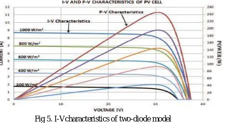
Theequivalentcircuitparametersareextractedfromthemanufacturer’sdatasheet [9].Simulated two-diode model of PV array of I-V and P-V characteristics developed in MATLAB/Simulink is as shown in Fig 5[10].
Fig 5. I-Vcharacteristics of two-diode model
To validate the simulation results with manufacturer data sheet we need to compare both data. PV panel at STC standard test condition, solar insolation of 1000W/ , cell operating temperature at 25 C are shown in Table 1[10].
ElectricalParame ters
ManufacturerData-sheet
Two-diodemodelof PVPanel inSimulink
Voc 37.5V 37.5V
Isc 8.73A 8.73A
Pmax 245W 249.4W
Vmpp 30.5V 32.75V
Impp 8.04A 7.61A
TABLE1. Comparison of Simulated data with manufacturer datasheet at STC
III. MPPTCONTROLLOGICIMPLEMENTATION
IGBT based boost converter is used which converts dc regulated voltage from unregulated dc voltage. The MPPT controlled boost converter is as shown in Fig.6.Boost converter consisting various elements namely inductor (L), filter capacitance ( C ), resistance (R),diode (D) and duty cycle switch.
Fig.6. MPPT controlled Boost converter for PV system
The design of boost converter which includes Duty cycle can be calculated as
Where V0 =output voltage of boost converter
Vs = Input voltage of boost converter
D = Duty cycle used to control the ON/OFF state of IGBT
Selection of inductor, capacitor is calculated as follows [11].
Inductance is selected on the basis of maximum allowed ripple current at two conditions one is at minimum duty cycle Dmin value and other is at maximum input voltage (Vs). For calculating the critical inductance always converter to be operated in continuous conduction mode and critical inductance is less than the boost inductance (L>Lb).
=(1− )∗ ∗
2 − − − − − − −(9)
Where Lb= critical inductance is calculated as the boundary edge between continuous and discontinuous mode of the
boost converter.
R = Equivalent load resistance
fs = Switching frequency of IGBT boost converter
A larger capacitor is used as filter at output side to limit theVoltage ripples at output side. Output filter capacitors are selected to meet maximum voltage ripple at output side. A larger capacitor is used as filter at output side to limit the Voltage ripples at output side. Output filter capacitors are selected to meet maximum voltage ripple at output side.
= 0∗
∗ ∆ 0∗ − − − − − −(10)
Where, ΔVo = Output voltage ripple selected in the range 5% less than Vo i.e. (ΔVo < Vo)
The different control logics are used in the MPPT for different cases as follows, which are namely P&O, FUZZY and ANFIS.
Perturb & observe (P&O) method is direct, simple and most common method for PV models. Perturbation refers to the increase or decrease in power. This is also called a “trial and error” method. Thus the implementation cost and time complexity is very less .The algorithm and flow chart of P&O algorithm for MPPT in [12].Simulink implementation of P&O logic for MPPT as shown in fig 7. In a PV system Perturb & Observe algorithm is taken as control logic for the MPPT. In P&O algorithm Voltage and current is taken as the inputs to the controller, are investigated in [13]. This control logic will computes the duty cycle continuously then the power electronic switch will control the boost converter and gives the desired boosting level.
A mamdani FUZZY logic controller is selected as controller for The MPPT shown in fig 8. In this logic error (Ek) and change in error (CEk) are taken as the inputs to the controller. They can be computed by considering Photo voltaic input current (Ipv) and voltage (Vpv) as the initial values from the PV panel, error and change in error can be calculated by the ratio of rate of change of power ∆P to the rate of change of voltage ∆V [14].
( ) = ∆ /∆ − − − − − −(11) ( ) = ( )− ( −1) − − − − − −(12)
Where
∆ = hangeinpower = ( )− ( −1)
∆ = changeinvoltage = ( )− ( −1)
Ek = Error
CEk = Change in error
Matlab / Simulink implementation of fuzzy logic system is as shown in fig 8.
Fig.8 Subsystem Implementation of MPPT control for Fuzzy logic
The rules for the mamdani FUZZY system implementation are as shown in below Table III.
Fig.8 Rule based fuzzy logic implementation
The generated duty cycle is to control the boost converter switch which tracks the MPP [15].A Seven subset of (7x7) forty-nine rules is used in the system and for the tuning of forty nine rules will take time, but it gives good dynamic response (Nonlinear response) and accuracy.
Fig.9. MPPT Sub-system implementation for ANFIS system
ANFIS is the combination of two learning techniques (ANN and FUZZY) into a single machine. The working of ANFIS system needs training of the data which requires some known data that can be collected by two ways, one from the real time process and other way from the simulation of dynamic PV model [12]. Operating temperature and Insolation are taken as the inputs to the ANFIS controller. ANFIS system implementation of MPPT is as shown in fig 9 [11].The proposed ANFIS MPPT will gives maximum power (Pmax) from the PV array at the same actual power(Pactual) which comes from the PV array by sensing voltage and current. Both powers are compared and outcome is given to the PI controller as the error value. The PI controller will gives the signal to PWM generator to generate the high frequency signals (25 kHz) which compare with operating signal. Finally PWM signals will control the duty cycle of the MPPT boost converter [12].
IV. SIMULATED RESULTSANDDISCUSSION
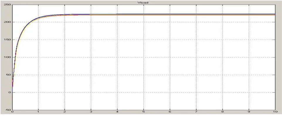
In the MATLAB/Simulink SPS is implemented at 1000 W/m2 irradiation and 25oc temperature to deliver a voltage of 220V (In order to generate 220v two Pv panel are connected in series to meet demand) and power of 400W to the DC load. The simulated results of SPS are as shown below. The SPS is implemented with the P&O algorithm, Fuzzy and ANFIS control logics for MPPT controller and the comparison of the simulated results as shown in Fig. 10-12. (Red line refers P&O, yellow refers fuzzy and blue refers ANFIS)
Fig.10.Simulated value of Load Voltage
fuzzy and ANFIS) in the SPS. It shows that the voltage of load value enhances when MPPT controller using ANFIS control logic. ANFIS boost up to the desired value of 220V load voltage in 1.58sec, whereas the system with MPPT fuzzy controller will reach at 1.62 sec and MPPT P&O controller reaches the same output voltage at 1.9sec.(Red line refers P&O, yellow refers fuzzy and blue refers ANFIS)
Fig.11. Simulated value of Load Current
The Fig.11 shows that the system with MPPT ANFIS controller brings the current of load to the required value of 0.4942amps in 1.58sec, whereas the system with fuzzy output current reaches at 1.62 sec and MPPT P&O controller reaches the required output current at 1.9sec.(Red line refers P&O, yellow refers fuzzy and blue refers ANFIS)
Fig.12. Simulated result of Load Power of SPS
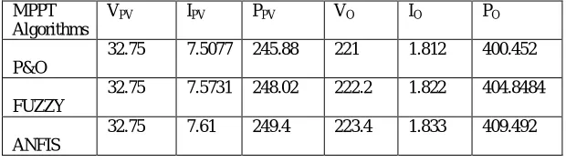
the system with fuzzy output power reaches at 1.62 sec and MPPT P&O reaches same output current at 1.9sec.The performance comparison of load voltage, load current and load power for various control logics as show in the table III.
MPPT Algorithms
VPV IPV PPV VO IO PO
P&O
32.75 7.5077 245.88 221 1.812 400.452
FUZZY
32.75 7.5731 248.02 222.2 1.822 404.8484
ANFIS
32.75 7.61 249.4 223.4 1.833 409.492
Table III. Performance comparison of ANFlS, Fuzzy and P&O
The system with MPPT ANFIS controller shows significant improvement in the load power than the other two MPPT control logics as shown in table IV.
Various Conditions Tracking Methods Power (W) Tracking Speed Maximum Power(W) %Tracking Efficiency 1000W/m2 250C
P&O 404.6 1.90
400
94.34
FUZZY 404.9 1.62 94.78
ANFIS 405.2 1.58 95.82
Table IV. Power comparison of ANFlS, Fuzzy and P&O
It is clearly shows that the MPPT controller plays a very much key role in the solar power system. We require a fast MPPT controller in order to improve the efficiency and performance by reducing the losses in the solar system. A MPPT controller with ANFIS control logic algorithm serves for this purpose.
V. CONCLUSION
MPPT using P&O algorithm reaches the maximum point in 1.9sec, whereas fuzzy logic can take to reach MPP value in 1.62 sec, finally ANFIS system makes the system to reach MPP in a less time than previous methods i.e. 1.58sec. The two MPPT methods are developed (P&O and artificial neural networks) and are compared together. The proposed neural network method i.e. ANFIS gives accurate results and faster response than the other two methods (P&O, fuzzy logic). The efficiency of the systems is in the ascending order as follow as ANFIS > FUZZY > P&O. So finally ANFIS system gives the better results in faster rate.
REFERENCES
1.Foster, R., M. Ghassemi, and A. Cota, Solar energy: renewable energy and the environment. 2010, Boca Raton: CRC Press.
2.Salam, Z.; Ishaque, K.; Taheri, H., "An improved two-diode photovoltaic (PV) model for PV system," 2010 Joint International Conference on Power Electronics, Drives and Energy Systems (PEDES)& 2010 Power India, pp.1,5, 20-23 Dec. 2010.
3.Yuncong Jiang; Qahouq, J.A.A.; Orabi, M., "AC PV solar system distributed architecture with maximum power point tracking," IEEE 34th International Telecommunications Energy Conference (INTELEC), pp.1-5, Sept. 30 2012-Oct. 4 2012.
4.Yuncong Jiang; Qahouq, J.A.A.; Batarseh, I., "Improved solar PV cell Matlab simulation model and comparison," Proceedings of 2010 IEEE International Symposium on Circuits and Systems (ISCAS), pp.2770- 2773, May 30 2010-June 2 2010.
5.Mahmoud, Y.A.; Weidong Xiao; Zeineldin, H.H., "A Parameterization Approach for Enhancing PV Model Accuracy," IEEE Transactions on Industrial Electronics, vol.60, no.12, pp.5708-5716, Dec. 2013.
6.Nikhil, P.G.; Subhakar, D., "An improved simulation model for photovoltaic cell," International Conference on Electrical and Control Engineering (ICECE), pp.1978-1982, 16-18 Sept. 2011.
8.A V Pavan Kumar; Alivelu M Parimi; K Uma Rao, “A Comparative Study of Model Based Design of PV cell in MATLAB / Simulink / Simscape” International Journal of Advanced Trends in Computer Science and Engineering, Vol. 3 , No.1, Pages : 37 - 42 (2014).
9.http://www.solaruk.net/pdf/DS%20-%20Sharp % 20 NU %20 Series % 20235 W-245W%20-%20Data%20Sheet.pdf.
10. A.V. Pavan Kumar, Alivelu M. Parimi, K. Uma Rao “Implementation of MPPT Control Using Fuzzy Logic in Solar-Wind Hybrid Power
System” IEEE2015 IEEE International Conference on Signal Processing, Informatics, Communication and Energy Systems (SPICES),pp.15,19-21 Feb. 2015
11. Ravinder K. Kharb, Md. Fahim Ansari, S. L. Shimi "Design and Implementation of ANFIS based MPPT Scheme with Open Loop Boost
Converter for Solar PV Module" International Journal of Advanced Research in Electrical, Electronics and Instrumentation Engineering , Vol. 3, Issue 1, January 2014.
12. A. Padmaja ,M.Srikanth"Design of MPPT Controller using ANFIS and HOMER based sensitivity analysis for MXS 60 PV module" International Journal of Innovative Research in Advanced Engineering (IJIRAE) ISSN: 2349-2163 Issue 11, Volume 2 (November 2015)
13. A V Pavan Kumar; Alivelu M Parimi; K Uma Rao, “Performance Analysis of a Two-Diode model of PV cell for PV based generation in
MATLAB”, IEEE International Conference on Advanced Communication Control & Computing (ICACCCT), pp.68-72, May 8- 10th, 2014 Chennai, India.
14. Hasan Mahamudul, Mekhilef Saad, and Metselaar Ibrahim Henk, “Photovoltaic System Modeling with Fuzzy Logic Based Maximum
Power Point Tracking Algorithm,” International Journal of Photo energy, vol. 2013, Article ID 762946, 10 pages, 2013.