Orcad
®
Layout
Cadence PCB Systems Division 13221 SW 68th Parkway, Suite 200 Portland, OR 97223
Trademarks
Allegro, Ambit, BuildGates, Cadence, Cadence logo, Concept, Diva, Dracula, Gate Ensemble, NC Verilog, OpenBook online documentation library, Orcad, Orcad Capture, PSpice, SourceLink online customer support, SPECCTRA, Spectre, Vampire, Verifault-XL, Verilog, Verilog-XL, and Virtuoso are registered trademarks of Cadence Design Systems, Inc.
Affirma, Assura, Cierto, Envisia, Mercury Plus, Quickturn, Radium, Silicon Ensemble, and SPECCTRAQuest are trademarks of Cadence Design Systems, Inc.
Alanza is a service mark of Cadence Design Systems, Inc.
All other brand and product names mentioned herein are used for identification purposes only and are registered trademarks, trademarks, or service marks of their respective holders.
Part Number 60-30-643 Second edition 31 May 2000
Cadence PCB Systems Division (PSD) offices PSD main office (Portland) (503) 671-9500
PSD Irvine office (949) 788-6080
PSD Japan office 81-45-682-5770
PSD UK office 44-1256-381-400
PSD customer support (877) 237-4911
PSD web site www.orcad.com
Contents
Before you begin ix
Welcome to OrCAD . . . ix
How to use this guide . . . x
Symbols and conventions . . . x
Related documentation . . . xi
Part one
Layout Basics
The Layout design flow 3
Chapter 1
Board-level schematic . . . 4Component placement . . . 4
Board routing . . . 5
Post processing . . . 5
Intertool communication . . . 6
Getting started 7
Chapter 2
Opening a design . . . 8Resolving missing footprint errors . . . 11
Resolving other AutoECO errors . . . 12
Saving a board . . . 13
Closing a board and exiting Layout . . . 14
The Layout design environment 15
Chapter 3
The design window . . . 16The library manager . . . 17
The session log . . . 18
The toolbar . . . 19
Viewing the current coordinates . . . 23
Viewing the current layer . . . 23
Using the postage stamp view . . . 24
The status bar . . . 24
Using help and the online tutorial . . . 25
The spreadsheets . . . 26
Editing spreadsheet information . . . 30
The query window . . . 31
Using Refresh Hot Link to query spreadsheets . . . 32
Pop-up menus . . . 32
Selecting and deselecting objects . . . 33
Editing object properties . . . 34
Undoing actions . . . 35
Setting environment preferences . . . 35
Display Preferences . . . 36
Global Preferences . . . 37
Copper Pour Preferences . . . 37
Miscellaneous Preferences . . . 38
Save User Preferences . . . 38
Using color in the graphical display of your board . . . 39
Part two
Creating a printed circuit board
Setting up the board 45
Chapter 4
Using technology templates . . . 46Custom templates . . . 47
Creating a board outline . . . 49
Setting units of measurement . . . 51
Setting system grids . . . 51
Adding mounting holes to a board . . . 54
Defining the layer stack . . . 55
Defining global spacing values . . . 56
Defining padstacks . . . 58
Defining vias . . . 59
Defining free vias . . . 60
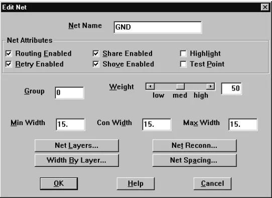
Setting net properties . . . 61
The Edit Net dialog box . . . 62
Enabling layers for routing . . . 65
Setting net widths by layer . . . 66
Contents
v
Creating and editing obstacles 71
Chapter 5
Creating obstacles . . . 72
Selecting obstacles . . . 79
Editing obstacles . . . 79
Copying obstacles . . . 80
Moving obstacles . . . 81
Rotating obstacles . . . 81
Mirroring obstacles . . . 82
Exchanging the ends of obstacles . . . 82
Moving segments . . . 83
Creating circular obstacles . . . 83
Deleting obstacles . . . 84
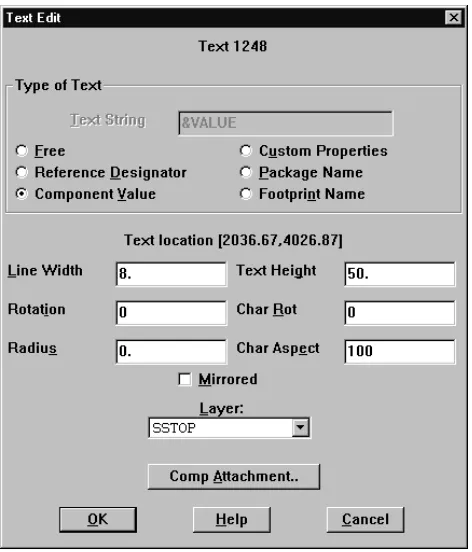
Creating and editing text 85
Chapter 6
Creating text . . . 86Moving text . . . 90
Deleting text . . . 91
Placing and editing components 93
Chapter 7
Preparing the board for component placement . . . 94Checking the board, place, and insertion outlines . . . 94
Checking the place grid . . . 95
Checking mirror layers and library layers . . . 96
Weighting and color-coding nets . . . 97
Checking gate and pin information . . . 98
Securing preplaced components on the board . . . 99
Creating height or group keepins and keepouts . . . 101
Loading a placement strategy file . . . 102
Disabling the power and ground nets . . . 103
Placing components manually . . . 103
Selecting the next components for placement . . . 104
Placing component groups . . . 105
Minimizing connections to optimize placement . . . 106
Copying, moving, and deleting components . . . 106
Swapping components . . . 107
Rotating components . . . 108
Mirroring components . . . 108
Placing components using a matrix . . . 109
Editing components . . . 111
Adding footprints to the board . . . 115
Checking placement . . . 116
Using Placement Spacing Violations . . . 116
Using the density graph . . . 117
Viewing placement statistics . . . 118
Routing the board 119
Chapter 8
Routing the board manually . . . 121Checking the board outline, via definitions, and routing and via grids . 121 Loading a routing strategy file . . . 121
Changing board density using routing strategy files . . . 122
Routing power and ground . . . 123
Defining a DRC box . . . 126
Fanout . . . 127
Creating split planes . . . 129
Verifying plane layer connections and disabling power and ground nets 132 Using manual routing tools . . . 133
Using add/edit route mode . . . 134
Using edit segment mode . . . 135
Using interactive routing tools . . . 137
Using shove track mode . . . 137
Using auto path route mode . . . 139
Creating duplicate connections . . . 140
Optimizing routing using manual routing commands . . . 141
Minimizing connections . . . 141
Changing the colors of nets . . . 141
Copying tracks . . . 142
Removing tracks . . . 142
Moving segments of tracks . . . 144
Changing the widths of tracks . . . 145
Forcing a net width on a layer . . . 145
Adding vias . . . 146
Adding a free via matrix . . . 146
Changing vias . . . 147
Changing free vias . . . 148
Using tack points . . . 149
Exchanging the ends of a connection . . . 150
Contents
vii
Creating nets . . . 151
Splitting nets . . . 151
Adding and deleting pins connected to nets . . . 152
Disconnecting pins from nets . . . 153
Generating test points interactively . . . 153
Checking routing . . . 154
Using Route Spacing Violations . . . 154
Viewing routing statistics . . . 155
Using thermal reliefs and copper pour zones 157
Chapter 9
Using thermal reliefs . . . 158Defining thermal reliefs . . . 158
Previewing thermal reliefs . . . 160
Rules that apply to creating thermal reliefs . . . 161
Forced thermal reliefs and preferred thermal reliefs . . . 162
Using padstacks to create thermal reliefs . . . 163
Creating copper pour zones . . . 164
Designating a seed point . . . 166
Creating a copper pour . . . 166
Ensuring manufacturability 171
Chapter 10
Checking design rules . . . 172Investigating errors . . . 173
Removing violations . . . 174
Cleaning up your design . . . 174
Post processing 175
Chapter 11
Renaming components . . . 176Back annotating . . . 177
Documenting board dimensions . . . 178
Viewing the Post Process spreadsheet . . . 180
Previewing layers . . . 182
Moving the drill chart . . . 185
Generating a drill tape . . . 186
Using Run Post Processor . . . 187
Creating reports . . . 188
Part three Libraries
About libraries 193
Chapter 12
Libraries . . . 194
Footprints . . . 195
Managing footprint libraries 197
Chapter 13
Starting the library manager . . . 198Making libraries available for use . . . 199
Viewing footprints . . . 200
Creating a custom footprint library . . . 201
Adding, copying, and deleting footprints . . . 203
Creating and editing footprints 205
Chapter 14
Setting a grid for the footprint pins . . . 206Creating a footprint . . . 206
Adding pins to a footprint . . . 207
Assigning padstacks to footprint pins . . . 208
Attaching obstacles to footprints and pins . . . 210
Adding labels to footprints . . . 211
Moving the insertion origin . . . 211
Editing footprints and footprint pins . . . 212
Editing padstacks . . . 213
Copying padstack layers . . . 214
Understanding the files used with Layout 217
Appendix A
System files . . . 218Design files . . . 219
Library files . . . 219
Report files . . . 219
Netlist files . . . 220
Board files . . . 220
Board templates . . . 221
Technology templates . . . 221
Strategy files . . . 226
Glossary 233
Before you begin
Welcome to OrCAD
OrCAD offers a total solution for your core design tasks: schematic- and VHDL-based design entry; FPGA and CPLD design synthesis; digital, analog, and mixed-signal simulation; and printed circuit board layout. What’s more, OrCAD’s products are a suite of applications built around an engineer's design flow—not just a collection of
How to use this guide
This guide is designed so you can quickly find the information you need to use OrCAD Layout. To help you learn and use Layout efficiently, this manual is separated into the following sections:
• Part One contains the basic information you need to get started using Layout. It explains the role of Layout in the printed circuit board (PCB) design flow,
describes how to start Layout, and introduces the Layout work environment.
• Part Two contains information about setting up the board, and then populating it with obstacles, text, and components.
• Part Three contains information concerning libraries and footprints.
Symbols and conventions
OrCAD printed documentation uses a few special symbols and conventions.
Notation Examples Description
C+r Press C+r Means to hold down the C key while pressing r.
A, f, o From the File menu, choose Open (A, f,
o)
Means that you have two options. You can use the mouse to choose the Open command from the File menu, or you can press each of the keys in
parentheses in order: first A, then f, then o.
Monospace font In the Part Name text box, type PARAM. Text that you type is shown in monospace font. In the example, you type the characters P, A, R, A, and
M.
How to use this guide
xi
Related documentation
In addition to this guide, you can find technical product information in the online Help, the online interactive tutorial, online books, OrCAD’s technical web site, as well as other books. The table below describes the types of technical documentation provided with Layout.
Italics In Capture, save design_name.DSN. Information that you are to provide is shown in italics. In the example, you save the design with a name of your choice, but it must have an extension of .DSN.
This documentation component . . . Provides this . . . This guide—
OrCAD Layout User’s Guide
A comprehensive guide for understanding and using the features available in Layout.
Online Help Comprehensive information for understanding and using the features available in Layout.
You can access Help from the Help menu in Layout, by choosing the Help button in a dialog box, or by pressing
1. Topics include:
• Explanations and instructions for common tasks.
• Descriptions of menu commands, dialog boxes, tools on the toolbar and tool palettes, and the status bar.
• Error messages and glossary terms.
• Reference information.
• Product support information.
You can get context-sensitive help for a error message by placing your cursor in the error message line in the session log and pressing 1.
Online interactive tutorial A series of self-paced interactive lessons. You can practice what you’ve learned by going through the tutorial’s specially designed exercises that interact directly with Layout. You can start the tutorial by choosing Learning Capture from the Help menu.
Online Layout Quick Reference Card Concise descriptions of the commands, shortcuts, and tools available in Layout.
ODN—OrCAD Design Network at www.orcad.com/odn
An internet-based technical support solution. ODN provides a variety of options for receiving and accessing design and technical information. ODN provides:
• A Knowledge Base with thousands of answers to questions on topics ranging from schematic design entry and VHDL-based programmable logic design to printed circuit board layout methodologies.
• A Knowledge Exchange forum for you to exchange information, ideas, and dialog with OrCAD users and technical experts from around the world. A list of new postings appears each time you visit the Knowledge Exchange, for a quick update of what’s new since your last visit.
• Tech Tips that deliver up-to-the-minute product information in your email box. Stay informed about the latest advances, tips, and announcements on your OrCAD product.
• Online technical support via the Tech Support
Connection. Use this service to submit technical support incidents online. Create submissions, upload files, track your incidents and add comments directly into OrCAD’s support database.
Part one
Layout Basics
Part One contains the basic information you need to get started using Layout. It explains the role of Layout in the printed circuit board (PCB) design flow, describes how to start Layout, and introduces the Layout work
environment.
• Chapter 1, The Layout design flow describes where
Layout fits into the board design process.
• Chapter 2, Getting started explains how to start Layout,
load a board template, load a netlist, open a board, save a board, close a board, and exit Layout.
The Layout design flow
1
Layout supports every phase of the design process. A typical printed circuit board design flow has five key phases:
• Board-level schematic • Component placement • Board routing
• Post processing
Board-level schematic
Using a schematic capture tool, such as OrCAD Capture, you can create a Layout-compatible netlist that includes preset design rules to guide logical placement and routing. This gives you the ability to specify critical design rules at the schematic level, such as component locations, net spacing criteria, component group information, net widths, and routing layers, and bring them into Layout in a netlist. If the schematic netlist changes, you can reload it. Layout’s AutoECO (automatic engineering change order) utility updates the board without harming finished work.
Component placement
Whether you choose to use Layout’s manual placement tools, or the interactive and autoplacement utilities (available in Layout Plus only), you have ultimate control of the component placement process. You can place components individually or in groups.
During autoplacement, Layout’s shove capability moves components out of your way automatically while
adhering to design rule check (DRC) guidelines. You can autoplace components individually, by area, or you can autoplace the entire board.
Board routing
5
Board routing
With Layout, you can route your board manually, or you can use Layout’s interactive and automatic routing tools (available in Layout Plus and Layout only).
Using manual routing, you guide the routing process and manually route each track. Then you optimize routing using a variety of manual routing commands.
In interactive routing, you still control the routing of individual tracks, but can take advantage of Layout’s automatic routing technologies, such as push-and-shove, which moves tracks to make space for the track you are currently routing.
If you choose to use Layout’s autorouter, you can interrupt routing at any time to manage and control the routing process. You can autoroute a single track, a selected area of the board, a group of nets, or the entire board.
Post processing
In Layout, all of your output settings are stored in a spreadsheet that you can call up and revise. You can give layer-by-layer instructions for writing to Gerber files, DXF files, or hardcopy devices.
Layout produces more than twenty standard reports, including fabrication drawings, assembly drawings, and pick-and-place reports. In addition, you can create custom reports of your own.
Intertool communication
Layout has the ability to communicate interactively with OrCAD Capture and OrCAD Express using intertool communication (ITC).
You can use intertool communication to communicate updated schematic information to Layout at any stage of the design process. Also, you can back annotate board data to Capture or Express from Layout.
Getting started
2
This chapter describes how to: • load a board template • load a netlist
Opening a design
You can open a new design or an existing design. When you open a new board design, Layout prompts you to choose a template and a schematic netlist. A board template provides the framework within which you can create a board design. A netlist describes the parts and interconnections of a schematic design.
A board template (file_name.TPL) contains a board outline and design rules from Layout’s default technology template, DEFAULT.TCH. DEFAULT.TCH, described in
Appendix A, Understanding the files used with Layout,
contains the following parameters, among others: • 62-mil pads
• 12-mil tracks • 12-mil spacing
The board templates, located in the LAYOUT/DATA directory, offer numerous, unique board outlines, which are listed and illustrated in the OrCAD Layout Footprint
Libraries manual. The board outline titles correspond to
the filenames of the board templates that contain them.
Tip
If you cannot use any of the board outlines provided with Layout,
you can create your own board outline. In this case, load a
technology template (.TCH) instead of a board template (.TPL)
when you open the new design. Then, create your own board
outline by following the instructions in Creating a board outline on
page 61.
If you choose to load one of the board templates (board outlines) provided with Layout, but DEFAULT.TCH is not suitable for your type of board, you can load a technology template to match the characteristics of your board, including manufacturing complexity and
Opening a design
9 Note
For more information on netlist files, board files, and technology
templates, and for a complete list of the technology templates
provided with Layout, see Appendix A, Understanding the files used
with Layout.
Tip
If you load a technology template after loading a board template,
you can save the result as a custom technology template for use
with future designs. See Using technology templates on page 58 for
more information.
A netlist file describes the interconnections of a schematic design using the names of the signals, components, and pins. A netlist file (.MNL) contains the following
information:
• Footprint names • Electrical packaging • Component names • Net names
• The component pin for each net • Net, pin, and component properties
You can create a Layout netlist directly in Capture or Express, or you can import Layout-supported netlists using a translator that corresponds to your schematic program. The translator creates the file design_name.MNL.
The AutoECO (Automatic Engineering Change Order) process combines a board template (.TPL) and a schematic netlist (.MNL) to produce a Layout board file (.MAX) that contains all of the board’s physical and electrical
information.
Caution
Running multiple copies of Layout is not recommended. When
multiple copies of Layout are running, data is shared between the
two copies. Performing processes like AutoECO or making edits in
the Library Manager can cause changes in other open copies.
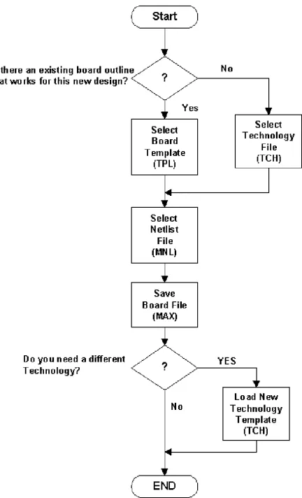
Figure 1 illustrates the process for opening a new design.
Figure 1 Opening a new board design in Layout.
To open a new design
1 From the File menu, choose New. The Load Template File dialog box appears.
2 Select a board template (.TPL or .TCH), then choose the Open button. The Load Netlist Source dialog box appears.
3 Select a netlist file (.MNL), then choose the Open button. TheSave File As dialog box appears.
For a complete list of board templates and illustrations of the board outlines they include, see the OrCAD Layout Footprint Libraries.
Note If you do not want to load one of the board outlines provided with Layout, load a technology template instead (.TCH). For more information about technology templates, and for a complete list of the technology templates provided with Layout, see Appendix A,
Opening a design
11 4 Supply a name for the new board file (.MAX), then
choose the Save button. AutoECO runs automatically, and displays its progress in an ASCII report file (.LIS). If there are no AutoECO errors, the new board opens in Layout’s design window.
Resolving missing footprint errors
If you are in the process of running AutoECO and it is unable to find a designated footprint, the Link Footprint to Component dialog box appears. Choose one of the options in the dialog box (described below) to resolve the error, so that the AutoECO process can continue.
Link existing footprint to component
Create or modify footprint library
Opens the library manager, which you can use to create or modify footprint libraries, as described in Chapter 13,
Managing footprint libraries and Chapter 14, Creating and editing footprints. When you’re finished, exit the library
manager (from the File menu, choose Exit) to return to AutoECO.
Defer remaining edits until completion
Continues to run AutoECO, then checks for errors at its completion. Layout reports missing footprints in an ASCII file (design_name.ERR).
Resolving other AutoECO errors
There are two other problems that can occur during the AutoECO process when opening a design.
• Mounting holes disappear from the board when you run AutoECO.
• The pin numbers from the schematic do not match the pad names in Layout.
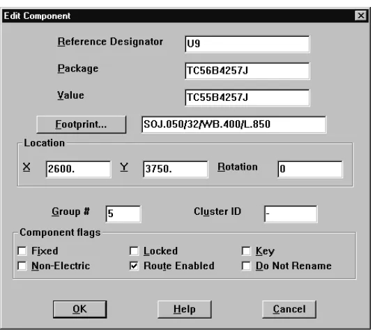
If an object, such as a mounting hole, is on the board but not in the schematic, specify it as non-electrical in the Edit Component dialog box. Otherwise, it may be deleted when you run AutoECO.
To define a component as non-electrical
1 Choose the spreadsheet toolbar button, then choose Components.
2 Locate and double-click on the component in the spreadsheet. The Edit Component dialog box appears.
Saving a board
13
Pin numbers in the schematic must match the footprint pin names in the footprint library files. For example, a diode in the schematic might have pins named Anode and Cathode, while the actual footprint has corresponding pin names of Ano and Cath. These differences must be reconciled or the design will not load. To correct this situation, do one of two things.
• Change the symbol pin names in the schematic to match the footprint pin names in the Layout library. • Change the footprint pin names in the library to match
the symbol pin names.
To open an existing board
1 From the File menu, choose Open. The Open Board dialog box appears.
2 Locate and select an existing board (.MAX), then choose the Open button.
3 If necessary, respond to the message asking if you want to update the board because the netlist has changed. The board opens in the design window.
Saving a board
To save a new board
1 From the File menu, choose Save As. The Save File As dialog box appears.
2 Select a folder, enter a filename in the File name text box, then choose the Save button. The board is saved, and remains open in the design window.
To save an existing board
1 From the File menu, choose Save. The board is saved in the directory it was opened from, and remains open in the design window.
To save a copy of a board
1 From the File menu, choose Save As. The Save File As dialog box appears.
2 Select a folder, enter a filename in the File name text box, then choose the Save button. A copy of the board is created. The copy of the board appears in the design window and the original file is closed.
Closing a board and exiting
Layout
To close a board
1 From the File menu, choose Close. Layout asks if you want to save your changes.
2 Choose either the Yes or No button. Layout displays an empty board in the design window.
To exit Layout
1 From the File menu, choose Exit. Layout asks if you want to save your changes.
The Layout design
environment
3
The design window
The library manager
17
The library manager
The library manager is used to view, create, and edit footprints and footprint libraries. The library manager is split into two windows: the library manager window and the footprint editor. The windows open simultaneously, and are tiled vertically.
In the library manager window, you can browse to select the libraries you want to modify during the current session. Once you select a library, you have access to all of the footprints in that library. Using the library manager, you can also create custom libraries, create footprints, and save new or modified footprints to the library of your choice.
The footprint editor is the primary window you use when creating and editing footprints. It provides a graphical display of the footprint and is specifically tailored for the creation and modification of individual footprints.
To open the library manager
1 Choose the library manager toolbar button or from the File menu, choose Library Manager.
To close the library manager, click on the X in the upper, right-hand corner in either the library manager window or the footprint editor, and choose the OK button when Layout asks if you want to close the library manager.
The session log
The toolbar
19
To open the session log
1 From the File menu, choose Text Editor. A text editor (such as Notepad) appears.
2 From the text editor’s File menu, choose Open. The Open dialog box appears.
3 Change the Files of type to All Files, locate and select LAYOUT.LOG, then choose the Open button. The session log opens in the text editor window.
The toolbar
By choosing a tool in the toolbar, you can quickly perform the most frequent Layout tasks. When you move the pointer over a toolbar button, the button’s name appears below the button, in what is referred to as a tooltip.
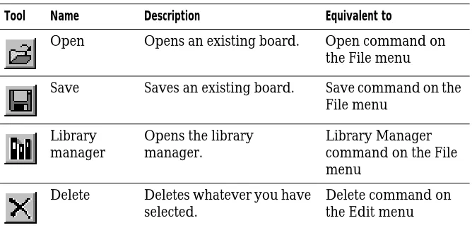
[image:31.612.100.434.493.656.2]The table below summarizes the functions of the toolbar icons. The functions are described in detail throughout this manual.
Table 1 The toolbar
Tool Name Description Equivalent to
Open Opens an existing board. Open command on the File menu
Save Saves an existing board. Save command on the File menu
Library manager
Opens the library manager.
Library Manager command on the File menu
Delete Deletes whatever you have selected.
Delete command on the Edit menu
The same toolbar appears when you’re using the library manager, although some buttons are unavailable (and appear dimmed) because they do not apply to the current activity.
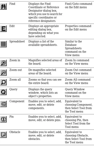
Find Displays the Find Coordinate or Reference Designator dialog box, which you use to search for specific coordinates or reference designators.
Find/Goto command on the Edit menu
Edit Displays an appropriate editing dialog box, depending on what you have selected.
Properties command on the Edit menu
Spreadsheet Displays a list of the available spreadsheets.
Similar to the Database Spreadsheets command on the View menu Zoom in Magnifies selected areas of
the board.
Zoom In command on the View menu Zoom out De-magnifies selected
areas of the board.
Zoom Out command on the View menu Zoom all Zooms so that you can see
the entire board.
Zoom All command on the View menu Query Displays the query
window, which lists an object’s properties.
Query Window command on the View menu Component Enables you to select, add,
move, edit, or delete components.
Equivalent to
choosing Component, then Select Tool from the Tool menu Pin Enables you to select, add,
move, edit, or delete pins.
Equivalent to choosing Pin, then Select Tool from the Tool menu
Obstacle Enables you to select, add, move, edit, or delete obstacles.
[image:32.612.183.513.147.659.2]Equivalent to choosing Obstacle, then Select Tool from the Tool menu
The toolbar
21
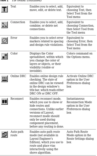
Text Enables you to select, add, move, edit, or delete text.
Equivalent to choosing Text, then Select Tool from the Tool menu
Connection Enables you to select, add, combine, or delete net connections.
Equivalent to
choosing Connection, then Select Tool from the Tool menu Error Enables you to select error
markers related to spacing and design rule violations.
Equivalent to choosing Error, then Select Tool from the Tool menu
Color Displays the Color
spreadsheet, within which you change the color of layers or objects, or their visibility (visible or invisible).
Colors command on the Options menu.
Online DRC Enables online design rule checking. The state of online DRC can be viewed in the design window’s title bar, which reads either DRC ON or DRC OFF.
Activate Online DRC option in the User Preferences dialog box
Reconnect Enables reconnect mode, which you use to show or hide routes and
connections. Unlike earlier versions of Layout,
reconnect mode should only be used during component placement, before any routing is done.
Instantaneous Reconnection Mode option in the User Preferences dialog box
Auto path route
Enables auto path route mode (not available in Layout Engineer’s
Edition), which you use to route and place vias interactively using the shove algorithm.
[image:33.612.99.436.138.676.2]Auto Path Route Mode option in the Route Settings dialog box
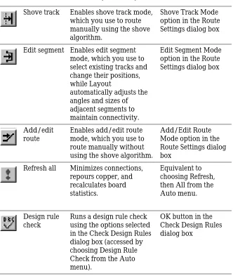
Shove track Enables shove track mode, which you use to route manually using the shove algorithm.
Shove Track Mode option in the Route Settings dialog box
Edit segment Enables edit segment mode, which you use to select existing tracks and change their positions, while Layout
automatically adjusts the angles and sizes of adjacent segments to maintain connectivity.
Edit Segment Mode option in the Route Settings dialog box
Add/edit route
Enables add/edit route mode, which you use to route manually without using the shove algorithm.
Add/Edit Route Mode option in the Route Settings dialog box
Refresh all Minimizes connections, repours copper, and recalculates board statistics.
Equivalent to choosing Refresh, then All from the Auto menu.
Design rule check
Runs a design rule check using the options selected in the Check Design Rules dialog box (accessed by choosing Design Rule Check from the Auto menu).
[image:34.612.183.515.143.536.2]OK button in the Check Design Rules dialog box
Viewing the current coordinates
23
Viewing the current coordinates
The X and Y coordinates corresponding to the location of the cursor appear below the toolbar buttons. The value is measured in the units of measurement you specify in the System Settings dialog box, accessed by choosing System Settings from the Options menu.
Viewing the place grid
The current place grid setting appears directly below the toolbar buttons. The display reflects the Place grid value you specify in the System Settings dialog box, accessed by choosing System Settings from the Options menu in the design window.
Viewing the current layer
The active board layer and its color appear below the toolbar buttons in the layer drop-down list. You can change layers by choosing one from the list, or by typing the number corresponding to the layer you want. For example, type 1 to change to the top layer.
Using the postage stamp view
A miniature outline of the board appears at the far right of the toolbar buttons. You can use this to determine what your current view is in relation to the entire board. You can change the view by moving your cursor into the
postage stamp view and clicking on a different area. Or, you
can draw a window within the postage stamp view to zoom to that window. Double-clicking in the postage stamp view has the same effect as choosing Zoom All from the View menu.
The status bar
Using help and the online tutorial
25
Using help and the online tutorial
Layout’s online help is designed to complement this manual, and contains additional information that will help you become familiar with Layout. You can access help from the Help menu, from the Help buttons in the dialog boxes, or by pressing 1.
Help topics include:
• Detailed dialog box descriptions • Detailed command descriptions
• Explanations and instructions for common tasks • Product support information
The spreadsheets
Layout provides a variety of spreadsheets that you can use to view and edit board information. To display most of the spreadsheets, choose the spreadsheet toolbar button, then choose a spreadsheet. Or, choose Database Spreadsheets from the View menu and choose a
spreadsheet.
Because the routing-related spreadsheets are used in setting routing strategies, you can display them by choosing the spreadsheet toolbar button, choosing Strategy, then choosing a spreadsheet. Alternatively, from the Options menu, choose Route Strategies, then choose a spreadsheet. From the Options menu, choose Global Spacing to display the Route Spacing spreadsheet. Because the placement-related spreadsheet is used to set autoplacement strategy, you can display it by choosing the spreadsheet toolbar button, choosing Strategy, then choosing Place Pass. Alternatively, from the Options menu, choose Placement Strategy.
From the Options menu, choose Colors to display the Color spreadsheet, or choose Post Process Settings to display the Post Process spreadsheet.
Tip If you want to select every element in a spreadsheet, click in the leftmost column’s title cell.
The spreadsheets
27
Route Sweep
Use the Route Sweep spreadsheet to view the settings (routing window size, overlap percent, and sweep direction) for the six main routing sweeps Layout uses to try to route a board to 100%.
Route Pass
Use the Route Pass spreadsheet to view the routing strategies (via cost, retry cost, route limit, and attempts) and routing algorithms (heuristics, maze, Auto DFM, fanout, via reduce, and Auto CDE) Layout uses in its routing passes.
Route Layer
Use the Route Layer spreadsheet to view whether a layer is enabled for routing, the primary direction of a layer, its layer cost (a low cost for a layer indicates that the layer is preferred for routing), and its between pins cost (the cost of routing between pins on 0.100 (or less) centers).
Route Spacing
Use the Route Spacing spreadsheet to view the settings for the various spacing criteria (track to track, track to via, track to pad, via to via, via to pad, and pad to pad) Layout uses when routing and when checking for DRC violations.
Statistics
Use the Statistics spreadsheet to view general information about the board, including placement and routing data. The Enabled column reports the components and nets that are active. The Total column reports the enabled
Layers
Use the Layers spreadsheet to view, add, disable, or modify the board layers.
Padstacks
Use the Padstacks spreadsheet to view and edit the location, type, and size of pads. Each padstack has a name, slightly offset from the layer definitions, and a size defined for each layer. Plane layer padstack sizes define clearance.
Footprints
Use the Footprints spreadsheet to view, access, and edit the library of physical parts used in the board.
Packages
Use the Packages spreadsheet to view and edit the logical gate and pin information for gate and pin swapping.
Components
Use the Components spreadsheet to view and edit the component footprint, package name, location, rotation, routing status, and group.
Nets
Use the Nets spreadsheet to set net properties such as width, route enabling, plane layer enabling, and shove. These properties affect both manual and automatic routing.
Obstacles
The spreadsheets
29
Text
Use the Text spreadsheet to view and edit board text.
Error Markers
Use the Error Markers spreadsheet to view error types and error marker locations. You can delete error markers from the board by deleting them in the spreadsheet.
Drills
Use the Drills spreadsheet to view and edit drill sizes, symbols, and tolerance.
Apertures
Use the Apertures spreadsheet to view and edit D-codes and their widths, heights, and shapes.
Color
Use the Color spreadsheet to view and edit the color of a layer or objects, or to make a layer visible or invisible. Display the Color spreadsheet by choosing the color toolbar button, or choose Colors from the Options menu.
You can also use the Color spreadsheet to set color and visibility when post processing.
Post Process
Place Pass
Use the Place Pass spreadsheet to view and edit the settings (iterations, attempts, and maximum clusters) for the six placement operations (assign clusters, proximity place, adjust components, place clusters, swap
components, and swap pins) Layout Plus uses during autoplacement.
Editing spreadsheet information
Layout’s spreadsheets not only visually and structurally organize the information and elements that comprise your board, they also provide a means for editing board data. There are two ways to edit board data using the
spreadsheets. You can access dialog boxes by
double-clicking in a spreadsheet. Or, you can access a pop-up menu by pressing the right mouse button while in a spreadsheet.
To edit spreadsheet data
1 Choose the spreadsheet toolbar button and choose a spreadsheet.
2 Do one or more of the following:
• Double-click in a cell to open a dialog box with that cell’s information available and the other cell’s information unavailable (dimmed).
• Double-click in a column heading to open a dialog box with the column’s information available and other information unavailable (dimmed).
• Double-click in the first cell of a row to open a dialog box with all of the editable options for that row available.
Note The Place Pass spreadsheet is only available in Layout Plus.
The query window
31 • Double-click in the first column’s heading to open
a dialog box with all of the editable options for all of the rows of the spreadsheet available.
• Press the right mouse button to display a pop-up menu, then choose one of the commands.
The query window
The query window provides detailed data for an object selected in either the design window or in a spreadsheet. When you click on a keyword (marked with quotation marks) in the query window, information about that item appears in the query window, and the item is highlighted on the board.
If you click on a location (the X and Y coordinates given in brackets) in the query window, the location is highlighted on the board and marked with an “X.”
By placing the query cursor (shaped like a Q) in the query window and pressing the J key, an appropriate edit dialog box appears, so that you can edit data. By placing the query cursor in the query window and pressing the
T key, an appropriate search dialog box (the Find and Select Item dialog box or the Find Coordinate or Reference Designator dialog box) appears.
If you enter the name of an object and choose the OK button in the search dialog box, the information about the object appears in the query window and the object is highlighted on the board.
To open the query window
Using Refresh Hot Link to query spreadsheets
If you open a spreadsheet and choose Refresh Hot Link from its pop-up menu, any objects in the spreadsheet that are related to the object visible in the query window are highlighted on the board and in related spreadsheets. For instance, if you open both the Nets and Components spreadsheets and highlight GND in the Nets spreadsheet, its information appears in the query window, and the components attached to GND are highlighted in the Components spreadsheet.
Pop-up menus
You can display pop-up menus in the design window, library manager, and spreadsheets by pressing the right mouse button. Their commands are specific to the tool you are using. For instance, if you display a pop-up menu in the Design Window with a component selected, the commands will be different than if you had no component selected.
To access pop-up menus
Selecting and deselecting objects
33
Selecting and deselecting objects
This section describes the different ways to select individual objects and groups of objects. These selection methods work both in the design window and library manager.
There are two selection modes available in Layout: • autotool
• tool-specific
When you select the Activate AutoTool Select Mode option in the User Preferences dialog box, Layout selects objects without regard to the active tool. The active tool is the tool that you last selected for use. For example, if you last chose the component tool, it is the active tool.
If you have trouble selecting an object using autotool select, it may be too close to surrounding objects. Choose the appropriate tool before selecting the object. After selecting the object, Layout automatically returns to autotool select mode.
If you don’t select the Activate AutoTool Select Mode option, Layout uses the tool-specific method. This method of selection is useful if the board is dense and you have trouble isolating an object using the autotool select mode.
To select an object in autotool select mode
1 Click an object with the left mouse button.
To select multiple objects in autotool select mode
1 Press the C key and select each object.
Tip
In the design window, pins and error markers cannot be selected
using autotool select mode. Hence, you must choose the pin tool or
error tool first. However, in the library manager, pins can be
selected using autotool select mode, but components cannot.
The reasoning behind this is that, in general, you select a pin in the
footprint library, not an entire footprint. If you need to select an
entire footprint, choose the component tool first.
Tip If you pick up the correct object, but on the wrong layer, you can type the layer number for the appropriate layer.
To select an object using tools
1 Choose the appropriate tool for the object you want to select.
2 Press the C key and click the left mouse button with the pointer over the object. The selected object appears in the highlight color specified in the Color
spreadsheet.
To select multiple objects using tools
1 Press the C key and select each object or
hold the left mouse button while dragging the mouse, drawing a rectangle around the object or objects to select. Release the left mouse button.
The selected objects appear in the highlight color specified in the Color spreadsheet.
To deselect objects
1 Press the E key or click on an area where there are no objects.
Editing object properties
Each object has a set of property values that you can edit. Editing properties usually affects the appearance and function of an object.
To edit an object
1 Select the object.
2 Choose the Properties command from the pop-up menu. An appropriate editing dialog box appears.
3 Change the values as necessary, then choose the OK button.
Undoing actions
35
Undoing actions
When you’re using tools such as the component tool, the Undo command is available on both the Edit menu and the pop-up menu. The Undo command returns the board to the state that existed before the last action was taken.
To undo the last action
1 From the pop-up menu, choose Undo or from the Edit menu, choose Undo.
Setting environment preferences
In Layout, you can edit the default settings that affect your design environment.
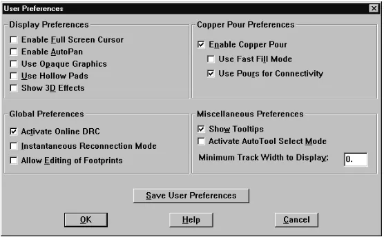
To set user preferences
1 From the Options menu, choose User Preferences. The User Preferences dialog box appears.
[image:47.612.100.378.487.659.2]2 Edit the options to reflect your preferences and requirements, then choose the OK button.
Display Preferences
Enable Full
Screen Cursor
Changes the cursor to a full screen cursor, with X and Y axes that extend the width and height of the design window.Enable Auto
Pan
With an object selected, placing the pointer at the horizontal edge of the design window causes Layout to pan in the direction of the pointer. The pointer and selected object move to the middle of the screen after panning.Use Opaque
Graphics
When selected, tracks and other objects are solid. You cannot see what, if anything, is under them. When not selected, tracks and other objects are translucent and you can see the tracks and objects beneath them.Use Hollow
Pads
Displayssquares or circles to reduce solid pads as hollow redrawing time. They do not print or plot as hollow.Show 3D
Setting environment preferences
37
Global Preferences
Copper Pour Preferences
Activate
Online DRC
Enables online design rule checking. Equivalent to choosing the online DRC toolbar button. With this option selected, you can only draw routes that conform to your space settings.Instantaneous
Reconnection
Mode
Enables reconnect mode, which you can use to show or hide nets.
Equivalent to choosing the reconnect toolbar button.
Allow Editing
of Footprints
Enables you to edit component footprints on the board without opening the library manager. You can edit obstacles, text, and pins attached to separate components.Enable Copper
Pour
Enables copper pour drawing and refreshing. You must select this option in order to select the Use Fast Fill Mode option or the Use Pours for Connectivity option.Use Fast Fill
Mode
Reduces the drawing time for copper pour by using a simple pattern to represent copper pour on your screen. This option only affects the display of the copper pour on the screen. It does not accelerate the actual pour process.Use Pours for
Connectivity
Layout considers connections to be routed when they exist in a copper pour, provided that the copper pour is common to the same net as the pins.Miscellaneous Preferences
Save User Preferences
Show Tooltips
Displays tool descriptions as you pass your cursor over the toolbar buttons. It also enables the use of pop-up dialog boxes as error indicators. If you do not select this option, Layout uses beeps to indicate errors and displays the errors in the status bar.Activate
AutoTool
Select Mode
Enables you to select an object without having to choose the appropriate tool first.
Minimum
Track Width to
Display
Reduces the redraw time for wide tracks by using a minimum width to represent the tracks. Layout draws tracks wider than this setting as actual size, and draws all other tracks as a single pixel line.
Save User
Preferences
Button
Using color in the graphical display of your board
39
Using color in the graphical
display of your board
Layout assigns a default color for each board layer. You can use the Color spreadsheet to edit the colors used in the graphical display and to make layers visible or invisible.
To open the Color spreadsheet
1 Choose the color toolbar button or
from the Options menu, choose Colors. Layout displays the Color spreadsheet.
To change the color of an object or layer
1 Select an item in the Color spreadsheet.
2 From the pop-up menu, select a new color for the item or click the Define Custom Colors button to create a custom color.
3 Choose the OK button.
4 Close the Color spreadsheet. The item appears in the new color.
Tip You can save a color scheme as a strategy file for use with future boards. To do so, define the colors using the instructions in this section, then use the Save As command (from the File menu) to save the file with an .SF extension.
Note Layout uses a different process for specifying the colors you want to use for preview and output. For information on using color during post processing, see Previewing layers on page 194.
Note Diagonal lines within a color box indicate that a layer and the objects on that layer are set to invisible.
To make a layer visible or invisible
1 Select a layer in the Color spreadsheet.
2 From the pop-up menu, choose Visible<>Invisible. The color appears as a solid color if you made the layer visible, or as a diagonal pattern if you made the layer invisible.
3 Close the Color spreadsheet.
To add an object to the Color spreadsheet
1 In the Color spreadsheet, choose New from the pop-up menu. The Add Color Rule dialog box appears.
2 Select the item that you want to add and specify the layer that the item is on in the Layer text box. A dash indicates “any layer,” signifying any occurrence of the object.
3 Choose the OK button.
Using color in the graphical display of your board
41
To delete an object or layer from the Color spreadsheet
1 Select the object or layer in the Color spreadsheet and press the D key. The object or layer no longer appears in the design window.
Part two
Creating a printed circuit
board
Part Two contains the following information:
• Chapter 4, Setting up the board describes how to set up a
new board.
• Chapter 5, Creating and editing obstacles obstacles
describes how to create obstacles for footprint libraries and boards. Obstacles include board outlines, place outlines, group and height keepins and keepouts, and copper zones.
• Chapter 6, Creating and editing text explains how to use
text in Layout.
• Chapter 7, Placing and editing components explains how
to place components on the board using Layout’s manual place tools.
• Chapter 8, Routing the board explains how to use
describes how to use thermal reliefs and copper pour zones in Layout.
• Chapter 10, Ensuring manufacturability explains how to
use Layout’s design rule and manufacturability checks to test the integrity of the board.
• Chapter 11, Post processing describes how to rename
Setting up the board
4
In Layout, you should set up the board before you begin placing components. This chapter explains how to set up a board by combining a board template or a technology template with other Layout commands and processes.
The steps involved in the board setup process are listed below, but not all of them are necessary for every board. • Load a template
• Create a board outline • Set the units of measurement • Set system grids
Using technology templates
When creating a new board design, Layout asks you for a template file to use. There are two kinds of templates that you can indicate for use:
• technology (.TCH) • board (.TPL)
Technology templates let you establish design standards and manufacturing complexity. Layout comes with several technology templates to choose from, including a default template. See Appendix A, Understanding the files
used with Layout for a detailed discussion.
A board template conatins physical board objects such as a board outline, mounting holes, and so on. Layout comes with several board templates to choose from.
You can load either type of template when creating your design. If you load a board template, the default
technology template is included. If the default technology template does not satisfy your design standards and manufacturing complexity requirements, you can load one that does.
If you load only a technology template, there will be no physical board objects upon opening.
To load a template
1 From the File menu, choose Load. The Load File dialog box appears.
2 Select either a board (.TPL) or technology (.TCH) template.
3 Click the Open button.
When you load a new technology template, some existing board data is overwritten, and some is ignored.
Using technology templates
47
Custom templates
It is easiest to create a custom template by modifying an existing board template and saving it under a new name, but you can also start with an empty board file. You can use your custom template with any Layout board.
You may want to create a custom template if, for instance, you want to use a board outline provided with Layout, but need more from the technology template than DEFAULT.TCH can offer. Or, you may want to create a custom template if you are creating your own board outline. If you know that you will use the board outline in future boards, you can create a custom template that incorporates the outline and any other design rules you use often.
To create a custom template using one of Layout’s board outlines
1 From the File menu, choose Open. The Open Boarddialog box appears.
2 Change Files of type to All Files, open the DATA folder and select the board template (.TPL) that has the board outline you want to use, then choose the Open button. The board template opens in Layout.
3 From the File menu, choose Load. The Load File dialog box appears.
4 Change Files of type to Template, select the technology template (.TCH) you want to use, then choose the Open button. Layout loads the technology file.
5 Define other board criteria as necessary using the processes in this chapter.
6 From the File menu, choose Save As. The Save File As dialog box appears.
To create a custom template using your own board outline
1 From the File menu, choose New. The Load Template File dialog box appears.
2 Choose the Cancel button. An empty board opens in the design window.
3 From the View menu, choose Zoom All. The entire board (its DRC box and drill chart) appears in the design window.
4 Create a board outline by following the instructions in
Creating a board outline in this chapter.
5 From the File menu, choose Load. The Load File dialog box appears.
6 Change Files of type to Template, select the
technology template (.TCH) you would like to save with the new board outline, then choose the Open button. Layout loads the technology file.
7 Define other board criteria as necessary using the processes in this chapter.
8 From the File menu, choose Save As. The Save File As dialog box appears.
9 Change Save as type to Template, select which folder to save the file in, supply a filename (with a .TPL extension), then choose the Save button.
To create a custom template from an existing board
1 Open the board you want to use as a basis for the template.
2 Choose the spreadsheet toolbar button, then choose Components. The Components spreadsheet appears.
Creating a board outline
49 4 In the Edit Component dialog box, select the
Non-Electric option for those items (such as mounting holes) that will not be in your netlist. (Double-click on an item in the Components spreadsheet to display the Edit Component dialog box.)
5 Choose the spreadsheet toolbar button, then choose Nets. The Nets spreadsheet appears.
6 Select all the nets in the spreadsheet, then press the
D key.
7 From the File menu, choose Save As. The Save File As dialog box appears.
8 Change Save as type to Template, select which folder to save the file in, supply a filename (with a .TPL extension), then choose the Save button.
Creating a board outline
Note
Layout requires exactly one board outline, on the global layer.
To create a board outline
1 From the Tool menu, choose Dimension, then choose Datum. Click on the lower left corner of the board outline to place the datum (to provide a starting grid for component placement). Press h to redraw the screen.
Note
Placing the datum in the lower-left corner of the board outline gives
you positive X, Y coordinates, while placing it in other corners gives
you negative coordinates (in your reports and post processing
results).
Caution
Because the board datum is used for all grids, if you move the
datum after component placement, your place, routing, and via
grids will all be affected. And, you may have difficulty replacing the
datum at the precise location you moved it from.
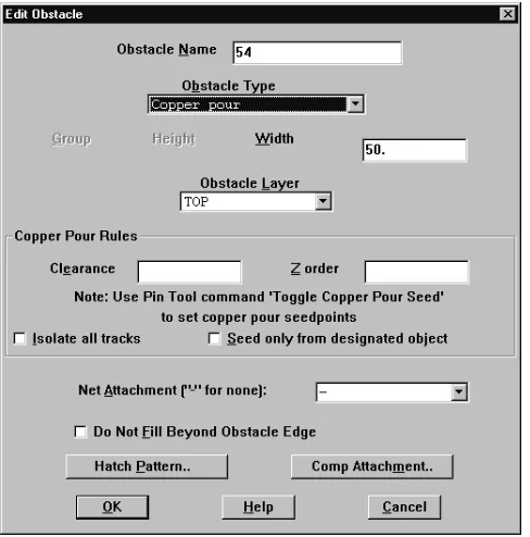
3 From the pop-up menu, choose New, then from the pop-up menu, choose Properties. The Edit Obstacle dialog box appears.
4 From the Obstacle Type drop-down list, select Board outline.
5 In the Width text box, enter a value for the outline’s width.
6 From the Obstacle Layer drop-down list, select Global Layer, then choose the OK button. The Edit Obstacle dialog box closes.
7 Move to the point on the board at which you want to start drawing the outline, then click the left mouse button to insert the first corner.
Because a board outline must be a closed polygon, Layout automatically begins forming a closed area after you insert the first corner of the board outline, and automatically closes the polygon for you if you don’t close it yourself.
8 Continue clicking the left mouse button to insert corners.
9 After you click to insert the last corner, choose Finish from the pop-up menu. Layout automatically
completes the board outline.
Tip Layout has a 50 mils default board outline width, in order to provide clearance on plane layers for the copper of the plane to the edge of the board. One-half of the width is the pullback (25 mils in the default width), so set the board outline’s width to two times the pullback you would like. The cut is made down the center of the board outline obstacle.
Tip If you zoom in while drawing, you can press C to put your current cursor
Setting units of measurement
51
Setting units of measurement
In Layout, you can set numeric data to display in mils, inches, microns, millimeters, or centimeters. You can change these values as needed (for example, you can route the board in inches or mils, then confirm pad locations within footprints in millimeters).
To set measurement units
1 Open your board in Layout.
2 From the Options menu, choose System Settings. The System Settings dialog box appears.
3 Select mils, inches, microns, millimeters, or centimeters.
4 Choose the OK button.
Caution
Once you decide on a measurement unit, you should stick with it
and not change it in either your board or your schematic. If you
back annotate to your schematic, then change to another
measurement unit, it may cause board corruption problems.
Setting system grids
Using the System Settings dialog box, you can set five distinct grid settings. The grid values that you assign determine the resolution of the pointer location
coordinates given in the status bar in the lower left corner. For example, if the obstacle tool is selected and the Place grid is set to 100 mils, the coordinates that display are accurate to 100 mils.
Grid values are in user-specified units that you set in the Display Units group box in the System Settings dialog box. If you want to use fractions in your grid values, enter a space character following the integer and use a forward slash as the division character (for example, 8 1/3). You can also use decimals for rational numbers.
Tip
Here are some rules of thumb for setting the grids:
For efficient routing performance, the routing grid and via grid
should have the same value.
The place grid must be a multiple of the routing and via grids.
The routing grid should never be less than 5 mils.
The detail grid can be set as low as 1 mil for better resolution.
Components are placed on the place grid using the component
datum, which is typically pad 1 (unless the component has been
modified).
To set system grids
1 From the Options menu, choose System Settings. The System Settings dialog box appears.
2 Set these options, then choose the OK button.
Visible grid
Assigns a display grid based on the X and Y coordinates (for example, if you’re using mils, a setting of 200 would place a grid dot at every 200 mils).
Detail grid
Assigns a drawing grid (for lines and text) based on the X and Y coordinates.
Place grid
Setting system grids
53
Routing grid
Assigns a grid used for routing (see the routing grid chart below for suggested settings).
Via grid
Assigns a grid upon which you or the router can place vias.
The following chart is a synopsis of routing grids and how to use them in Layout.
Routing grid Uses
Compatible grids 25, 121/2, 81/3, and 61/4:
25, 121/2
Use for less dense (usually .45 density or greater) through-hole and SMT boards, and for routing one track between IC pins.
81/3 Use for a secondary grid on through-hole boards,
and for a primary grid on SMT boards. Use as a secondary grid with 25 mils grid only if the 25 mils grid initially routes 95% or better.
61/4 Use for 6/6 technology, or denser
one-between boards. Compatible grids 20 and 10:
20 Use for through-hole boards only. This is the most efficient way to route two tracks between IC pins. 10 Use for through-hole, two-between boards placed
on a 50 mils grid, and for SMT boards using 10/10 technology. Also, use for special cases when a 20 mils grid causes off-grid jogs.
Compatible grids 25, 20, and 10:
Note
Incompatible grids (such as 20 and 25) should not be mixed on the
same board. If you find it necessary to do so, use a 5 mils grid for
the final reroute pass.
Also, a via grid smaller than the routing grid (for instance, a 5 mils
via grid on a 25 mils grid board) increases completion on difficult
SMT boards. Of course, if a board is very dense, via sizes should by
reduced to the minimum size possible, since vias are responsible for
much of the channel blockage during routing.
Adding mounting holes to a
board
You can add mounting holes to your board, and you can save them in a board template (.TPL). After adding the mounting holes to the board, define them as
non-electrical. You can still attach non-electrical mounting holes to the ground net. The non-electrical flag keeps the ECO process from removing them.
To add mounting holes to your board
1 Choose the component toolbar button.
2 From the pop-up menu, choose New. The Add Component dialog box appears.
3 Choose the Footprint button. The Select Footprint dialog box appears.
4 In the Libraries group box, select LAYOUT.LLB. Use the Add button, if necessary, to add this library to the list of available libraries. (LAYOUT.LLB resides in the LIBRARY directory.)
Defining the layer stack
55 6 Select the Non-Electric option, then choose the OK
button to close the Add Component dialog box. The mounting hole attaches to your cursor.
7 Place the mounting hole by clicking the left mouse button.
Tip
To have a mounting hole thermal into the plane layer, attach it to
the net that is shorted to the plane layer. You can do this after
placement.
If you don’t want a pad on the top, bottom, and inner layers, but
need clearance on the plane layers, place pads that are 1 mil in
diameter on the top, bottom, and inner layers. These 1 mil pads will
be seen by SmartRoute and avoided, and will be drilled out when
drill holes are drilled through the board. For the plane layers, you
need to define pads that are 15 mils larger than the drill hole, to
provide adequate clearance from the drill. Pad size on plane layers
is used to define clearance. Plane layers are represented in the
inverse, in Layout.
Defining the layer stack
Routing and documentation layers are defined in the Layers spreadsheet. Using the spreadsheet, you can define the number of routing layers that will be used for the board.
If you plan to have a board with four routing layers (TOP, BOTTOM, INNER1, and INNER2) and two plane layers (POWER, GROUND), then you need to define the layers in a technology template (.TCH) or a board template (.TPL).
Tip
It is better to have too many routing or plane layers defined than
too few (if you’re unsure of the number you will need) before
reading in a netlist, because you can decrease the number of the
layers later, by designating them as unused.