A SIMULATION ARCHITECTURE DESCRIPTION
LANGUAGE FOR HARDWARE-IN-LOOP SIMULATION OF
SAFETY CRITICAL SYSTEMS
YUJUN ZHU, ZHONGWEI XU, MENG MEI
School of Electronics & Information Engineering, Tongji University, Shanghai 201804, Shanghai, China
ABSTRACT
The architecture is a key aspect of the design of any system including simulation systems. An architecture description should provide a formal specification of the architecture in terms of components and connectors and how they are composed together. Further, a simulation architecture description for safety critical system must provide a specification of how the architecture can satisfy safety and execution characteristics. This paper introduces the simulation architecture description language for hardware-in-loop simulation of safety critical systems (SADL) to support the real-time simulation of safety critical systems. SCS-SADL is a graphical language with constructs and semantics defined to provide the user with the capability to define the simulation at various levels. A supporting toolset is proposed and provided the interface to SCS-SADL for the design simulation description. With a case study, SCS-SADL is illustrated its ability to represent the simulation of safety critical systems.
Keywords: Multicast Architecture Description Language, Safety Critical System, Hardware-in-loop
Simulation, Software Architecture
1. INTRODUCTION
Safety critical systems are those systems whose failure could result in loss of life, significant property damage, or damage to the environment. There are many well known examples in application areas such as medical devices, aircraft flight control, weapons, and nuclear systems. Future safety-critical systems will be more common and more powerful [1].The development of a safety critical system typically involves a period of simulation, especially, hardware-in-loop simulation(HILS). HILS provides a precise environment, access to physically immeasurable variables and rapid redesign and testing, not to mention sparing wear and damage on equipment. Additionally, some systems may present a danger in the event of system failure. For several decades, HILS has been a bridge between simulation and implementation [2]. Although each project is different, HILS of safety critical systems have requirements, characteristics and behaviors that can be used to define simulation architecture.
The simulation architecture is a description of the simulation and represents specific simulation methods. It includes architectural information such as the types of hardware and software components in the simulation, the interfaces among components,
and the software architecture. Simulation architectural design has always played a strong role in determining the success of HILS of safety critical system. However, the practice of simulation architectural design has been largely ad hoc, informal, and idiosyncratic. As a result, simulation architectural designs are often poorly understood by developers; simulation architectural choices are based more on default than solid engineering principles; simulation architectural designs cannot be analyzed for consistency or completeness; simulation architectural constraints assumed in the initial design are not enforced as a system evolves; and there are virtually no tools to help the simulation architectural designers with their tasks.
the hardware-in-loop simulation of safety critical systems.
2. RELATED WORK
In the last several years, There has been much research done involving ADL or SADL[4,5] and in the related area of hardware/software design [6]. Although all of the languages are concerned with architectural design, each provides certain distinctive capabilities: Aesop supports the use of architectural styles [7]; Adage supports the description of architectural frameworks for avionics navigation and guidance [8]; Meta-H provides specific guidance for designers of real-time avionics control software [9]; C2 supports the description of user interface systems using a message-based style [10]; Rapide allows architectural designs to be simulated, and has tools for analyzing the results of those simulations [11]; UniCon has a high-level compiler for architectural designs that supp ort a mixture of heterogeneous component and connector types [12]. A large challenge for an SADL is the ability to describe static but also dynamic software architectures from structural and behavioral viewpoints. The above languages cannot satisfy the real-time execution and support the hardware-in-loop activities, because the simulation software and/or hardware must meet the deadlines, periodic and aperiodic behavior imposed in the real environment, in addition, some attributes of language elements needed for completeness cannot be represented graphically. Exiting tools designed do not apply to the HILS of safety critical systems, creating a need for the tools tailored to this application domain. The objective of this paper is to present a simulation architecture description language for hardware-in-loop simulation of safety critical systems, called SCS-SADL, for the design, specification and implementation of the HILS. The constructs and semantics combine to provide the ability to define the HILS including the execution characteristics. SCS-SADL provides the designers with the capability to define the HILS at various levels.
3. SCS-SADL
SCS-SADL is an ADL specifically tailored to the design and representation of real-time safety critical system simulations. The focus on this application domain is what differentiates SADL from the existing ADLs discussed in the previous section. We now describe SCS-SADL, highlighting its key features. These key features are:
1. Components composing basic architectural design elements, representing the hardware devices and simulation software process.
2. Connectors describing the relationships those exit among the components, including the interactions among the hardware and software as well as abstract components.
3. Semantic reasoning about architectural descriptions, providing the basic structural semantics.
3.1 Components Definition
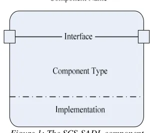
Components represent the primary computational elements and data stores of simulation system. Intuitively, they correspond to the boxes in box-and-line descriptions of simulation software architectures. Typical examples of components include such things as clients, servers, filters, objects, blackboards, and databases. Components are the locus of computation and state. Each component in SCS-SADL has:
a name
an interface a type
an implementation.
[image:2.612.346.496.434.567.2]The component in SCS-SADL is depicted in Figure 1.
Figure 1: The SCS-SADL component
specification that can be used as nodes in the graph representation.
Figure 2: The SCS-SADL Processes Representation
Periodic process, as its name implies, is used to represent simulation processes that execute periodically. A series of jobs associated with the process are invoked at regular time intervals. It can typically represent the simulation software having hard real-time requirements. Aperiodic process is used to represent simulation processes that execute aperiodically during the simulation. The jobs associated with this process do not instantiated at regular, predictable time intervals. Continuous process is invoked once at the beginning of the simulation and never suspends its execution by blocking. Instead, It polls, or busy waits, for external events or conditions consuming all of the computational resources of a processor for the entire duration of the simulation.
3.2 Connectors Definition
Connectors must represent all the timing and data relationships that exit among the simulation components and define the synchronization and communication requirements of each simulation software process of the simulation system, and they also represent the constraints imposed on the execution order of the processes, in effect defining the partial orders of execution among them. SCS-SADL uses a set of predefined directed arcs to connect the components in high-level diagrams and the nodes in low-level diagrams in a manner that represents the data flow, control flow, timing, and hierarchical relationships among the simulation components. The connectors defined in SCS-SADL include a component communication arc, a data transfer arc, a synchronization (sync) arc, and a synchronization-with-data (sync-with-data) arc [13].
The component communication is defined in the component level. The other three connectors are
used to describe the communication among the processes.
[image:3.612.313.522.183.290.2]The arcs are differentiated graphically using different line type, as shown in Table 1, and each has its own semantics that are described in the following sections.
Table 1: Connector Types And Their Associated Line Type In SCS-SADL
Connector type Line
Component Communication
Data Transfer
Synchronization
Synchronization-with-Data
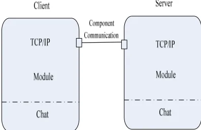
The component communication is used for abstraction purposes; it can only be used to connect the simulation component. So the component communication contains all the arcs that exist between the process nodes contained in a simulation component but do not represent any functionality of the simulation. Figure 3 shows a Client/Server pattern example for SCS-SADL component description using a component communication. A black line describes the component communication, one end of which is connected to the Server component interface, and other end to the Client component interface. The two components have a communication.
Figure 3: The Component Communication Connector Of High-Level Abstract
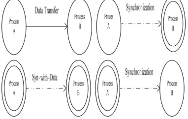
[image:3.612.323.521.470.598.2]synchronization and transfers data. The semantics associated with these types of connectors are different because of the different type of nodes that are connected. Figure 4 shows a example to express the difference of the connectors, here is not to enumerate.
Figure 4: The Different Type Of Connectors With Different Nodes
3.3 Semantic Description
[image:4.612.316.520.348.406.2]The graphs described in above sections represent only a single communication between one pair of simulation components. These relationships form the fundamental building blocks needed for the specification of more complex systems. The following content will give the semantic relationships for more complex systems.
Figure 5: A HILS Subsystem Graph Described Within SCS-SADL
Fig 5 shows a HILS subsystem graph described within SCS-SADL, such a graph can be specified in the following manner.
C(G)={C C C1, 2, 3} (1)
11 12 21 31
V(G)={p ,p ,p ,p }
(2)
11 21 31 12
E(G)={(p ,p ), (p ,p )}
(3)
31 12 11 21
P(G)={swd − ,df − }
(4)
Where
G
represents the graph,C(G)
is the setof components of graph
G
,V(G)
is the set ofvertices of graph
G
,E(G)
is the set of arcs ofgraph
G
where the ordered pair(
p
11,
p
21)
represents an arc from vertex
p
11 to vertexp
21.P(G)
is the set of connector properties of graphG
wheredf
11 21− represents a data transferconnector between
p
11 andp
21 ,swd
31 11−represents a synchronization-with-data connector property between
p
31 andp
12 .df
11 21− and31 11
swd
− can express the meaning showed in table 2. The properties about frequency and execution time are important for the interface of HILS system which will connect with the safety critical system; those properties can be represented in SCS-SADL.Table 2
A property description of SCS-SADL semantic
Property Name Frequency Execution Time
11 21
df
− 100HZ 5ms31 11
swd
− 30HZ 20ms4. TOOLSET FOR SCS-SADL
In order to use the SCS-SADL for the development of HILS of safety critical systems, there must be a toolset that can provide the engineers designing and implementing HILS systems. A prototype of SCS-SADL tool has been implemented to support the SADL. SCS-SADL tool allows engineers to design applications in a visualized way showed in Figure 6.
[image:4.612.100.296.431.555.2] [image:4.612.272.520.554.721.2]The SCS-SADL Toolset can provide the component design in the high-level abstract; it also can describe the process design in the low-level implementation. However, its function is only to provide the design view similar to the UML, the code can not be achieved automatically converted.
5. CASE STUDIES
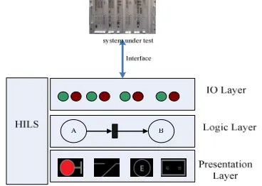
[image:5.612.101.285.258.389.2]A motivation example about the railway signal system will be illustrated. It needs to develop a HILS system for testing and evaluating the interlocking system, a typical safety critical system. The HILS system structure is showed in Figure 7.
Figure 7: The HILS System For Interlocking System.
There are three important components of this HILS system: Computation component, IO component, View component. Figure 8 shows using SCS-SADL to represent the partial architecture of the HILS for Interlocking system.
Figure 8: The Partial Architecture Description Of HILS For Interlocking System.
Where
p
21 is the process represented in Viewcomponent,
11
p
in Computation component and31
p
,32
p
in IO component.df
11 21− ,df
31 11− and11 32
swd
− are expressed like Table 2 to describe some safety critical properties.6. CONCLUSION
This paper presents an architecture description language, SCS-SADL, especially for applications in hardware-in-loop simulation because most existing
tools do not apply to the design of HILS of safety critical systems. This graphical specification language represents the simulation using a process graph representation as well as nonfunctional properties associated with each of the simulation components. A toolset has been developed and it provides the interfaces to complete the SCS-SADL. The future works is to setup an HILS framework for SCS-SADL and transforming SCS-SADL into UML or skeleton codes.
ACKNOWLEDGEMENTS
This work was supported by National Natural Science Foundation of P.R. China (61075002, 61273180).
REFERENCES:
[1] J. C. Knight, "Safety-critical systems: challenges and directions", Proceedings of International
Conference on Software Engineering, ACM
Press, May 19-25, 2002, pp.547-550.
[2] N. R. Gans, W.E. Dixon, R. Lind, A. Kurdila, "A hardware in the loop simulation platform for vision-based control of unmanned air vehicles",
Mechatronics, Vol. 19, No. 7,2009,pp.1043–
1056.
[3] D. Garlan, B. Monroe, D. Wile, "ACME: an interchange language for software architecture",
Proceedings of Centre for Advanced Studies Conference, IBM, November 10-13, 1997,
pp.159-173.
[4] P. Clements, "A survey of architectural description languages", Eight International
Workshop on Software Specification and Design, IEEE Computer Society Press, March
22-23, 1996, pp.16-25.
[5] P. Kogut, P. Clements, "Features of architecture description languages", Proceedings of Software
Technology Conference, Meridian, April 28-30,
1995, pp.1-10
[6] D. Garlan, R. Allen, J. Ockerbloom. "Exploiting style in architectural design environments",
Proceedings of the Second ACM SIGSOFT Symposium on the Foundations of Software Engineering, ACM Press, December 6-9, 1994,
pp.179-185.
[7] W. Tracz, "DSSA(domain-specific software architecture) pedagogical example", Software
Engineering Notes, Vol.20, No. 3, 1995,
pp.49-62.
[image:5.612.98.294.462.556.2]simulator", Proceedings of Digital Avionics
Systems Conference, AIAA/IEEE, October
26-30, 1997, pp.8-14.
[9] N. Medvidovic, P. Oreizy, J. E. Robbins, R. N. Taylor, "Using object-oriented typing to support architectural design in the C2 style",
Proceedings of the Fourth ACM Symposium on the Foundations of Software Engineering, ACM
Press, October 16-18, 1996, pp.24-32.
[10] D. C. Luckham, L. M. Augustin, J. J. Kenney, J. Veera, D. Bryan, W. Mann, "Specication and analysis of system architecture using Rapide",
IEEE Transactions on Software Engineering, Special Issue on Software Architecture, Vol. 21,
No. 4, 1995, pp.336-354.
[11] M. Shaw, R. DeLine, D. V. Klein, T. L. Ross, D. M. Young, G. Zelesnik, "Abstractions for software architecture and tools to support them", IEEE Transactions on Software Engineering, Special Issue on Software Architecture, Vol. 21, No. 4, 1995, pp.314-335.
[12] K. G. Ricks. J. M. Weir. B. E. Wells, "SADL: simulation architecture description language",