983
CONCEPTUAL FRAMEWORK FOR RECURSION IN
COMPUTER PROGRAMMING
SABAH AL-FEDAGHI
Assoc. Prof., Computer Engineering Department, Kuwait University
E-mail: [email protected]
ABSTRACT
Recursion is an important concept and a fundamental problem-solving technique in computer science. Studies have reported that it is considered a very difficult concept for students to learn and teachers to teach, and students have many misconceptions about recursion. Tools proposed to overcome these difficulties include visualization and algorithm animation. Conceptual models form the basis of methods for teaching recursion and influence the instructional tactics used when teaching it. Conceptual models of recursion have been found to provide a necessary representation for understanding the mechanics of recursion. Several of these models have been proposed, including the Russian dolls model, process tracing model, mathematical induction model, and structure template model. These are not based on a systematic foundation that visualizes the process in terms of flows of the recursive algorithm from the stages of creating (copying) then processing (executing) it. This paper presents such a methodical conceptual picture that describes the recursive process in a precise, visual way that assists in teaching and learning. The new model is illustrated by several examples, including factorial and binary tree traversing.
Keywords: Recursive Process, Recursion, Computer Programming, Conceptual Model
1. INTRODUCTION
Recursion is an important notion and a fundamental problem-solving technique in computer science. Some researchers claim that it should be a recurring or “basic concern throughout the discipline” [1]. A recursive problem solution is built from instances of the same type of problem, and then these problems are repeatedly solved using the successive application of instantiations. In computer programming this is accomplished by a “flow of control” that embeds flows until reaching a terminating instance then folding backward to end unfinished instances [2].
It is reported that recursion is a very difficult concept for students to learn and teachers to teach [3][4]. Students have many misconceptions about recursion and construct mental models which are non-viable [5]-[7].
Several reasons have been suggested for such problems, including difficulty in understanding passive flow of control [2] and suspended computation [8], and lack of everyday analogies [1]. Er [9] attributes the cause to a lack of conceptual model for illustrating recursive flow of control and also to the complexity of variable
binding, parameter passing, and environmental closure [9].
Many methods of teaching recursion have been proposed, such as concentrating on the concept of the base case [10]. Proposed tools include visualization [2][11]and algorithm animation [12].
According to Gotschi [5],
Conceptual models form the basis of methods for teaching recursion and will influence the instructional tactics used when teaching recursion. A conceptual model of recursion is one which provides an accurate and consistent representation of the mechanics of recursion.
In this context, a model is the conceptual representation of an abstract concept or a physical system that provides an explanatory instrument for understanding a concept or system [3]. It describes objects and their relations in the perceived world [3][13]. It is claimed that a conceptual model is necessary when learning recursion [14] since it would reduce misconceptions and enhance problem-solving abilities [15].
984 does not contain another. The process tracing model [17] traces process generation by recursive functions. The mathematical induction model [18] uses the mathematical basis of proof by induction. The structure template model [14] provides programs and descriptions of the base cases and recursive cases. The copies model approach utilizes a procedure of looping over a stack of function calls with self-triggering mechanism and control passing back from terminated instantiations [19] [20]
.
Still, these models are not based on a systematic foundation that visualizes the process in terms of flows of the recursive algorithm from stages of creating (copying) then processing (executing) it. This lack of systematic foundation becomes clearer when these models are contrasted with a new conceptual model proposed in this paper. Our proposed methodology describes the recursive process in a precise visual way that assists in teaching and learning.
The next section briefly reviews the basic framework used to model a recursive process.
2. FLOWTHING MODEL
To make this paper self-contained, the materials in this section are summarized from a series of papers that have applied the model in several application areas [21]-[25].
The Flowthing Model (FM) was inspired by the many types of flows that exist in diverse fields, such as, for example, supply chain flow, money flow, and data flow in communication models. This model is a diagrammatic schema that uses flowthings to represent a range of items that can be data, information, objects, or signals. FM also provides the modeler the freedom to draw the system using flowsystems that include six stages, as follows:
• Arrive: A flowthing reaches a new flowsystem
(e.g., a buffer in a router)
• Accepted: A flowthing is permitted to enter the
system (e.g., no wrong address for a delivery); if arriving flowthings are also accepted, Arrive and Accept can be combined as a Received stage.
• Processed (changed): The flowthing goes
through some kind of transformation that changes its form but not its identity (e.g., compressed, colored, etc.)
• Released: A flowthing is marked as ready to be
transferred (e.g., airline passengers waiting to board)
• Created: A new flowthing is born (created) in
the system (a data mining program generates the conclusion Application is rejected for input data)
• Transferred: The flowthing is transported
somewhere outside the flowsystem (e.g., packets reaching ports in a router, but still not in the arrival buffer)
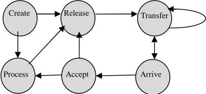
These stages are mutually exclusive, i.e., a flowthing in the process stage cannot be in the created stage or the released stage at the same time. Figure 1 shows the structure of a flowsystem. A flowthing is a thing that has the capability of being created, released, transferred, arrived, accepted, or processed while flowing within and between systems. A flowsystem depicts the internal flows of a system with the six stages and transactions among them. FM also uses the following notions:
• Spheres and subspheres: These are the
environments of the flowthing, such as a company and the departments within it, an instrument, a computer, an embedded system, a component, and so forth. A sphere can have multiple flowsystems in its construction if needed.
• Triggering: Triggering is a transformation
(denoted in FM diagrams by a dashed arrow) from one flow to another, e.g., flow of electricity triggers the flow of air. If a sphere has one flowsystem, then the two flows can be represented by one box.
A flowsystem need not include all the stages; for example, an archiving system might use only the stages Arrive, Accept, and Release. Multiple systems captured by FM can interact with each other by triggering events related to one another in their spheres and stages.
[image:2.612.328.530.520.612.2]
Figure 1. Flowsystem, Assuming That No Released Flowthing Is Returned
Create
Process Accept
Transfer Release
985 It may be argued that data can be in a stored state, which is not included as a stage of a flowsystem; however, stored is not a primary state, because data can be stored after being created, hence it is stored created data, or it is stored after being processed, hence it is stored processed data, and so on. Because current models of software and hardware do not differentiate between these states of stored data, we will assume flowsystems with unified storage.
3. APPLYING FM CONCEPTUALIZATION
TO RECURSIVE RELATIONS
A flowsystem can be viewed as having recursion according to its six stages. In this section we consider the situation where there is no recursive creation as we apply the notion of “recurring” to “objects” as an introduction to the modeling technique in FM.
Consider, for example, the entity-relationship (E-R) modeling that depicts a situation where, say, one employee manages another employee as a unary relationship, sometimes called a recursive relationship. Such a relationship is represented by drawing an ellipse and then connecting it to the entity twice. The semantics in this case mean that the entity Employee manages (many) Employee(s).
The recursion sense in this conceptual picture is based on the relationship of an entity with itself. But such a perspective comes from an arbitrary decision to halt further discreteness of the situation. It is analogous to describing marriage as a relationship between a person and a person. Similarly, manage can describe a relationship between a managing Employee and a managed Employee, until we reach the base of recursion, where there is an instance of an Employee who does not manage. This is not apparent in a marriage relation because the base is reached on one level, since there is no person who is married to another person who is in turn married to yet another person.
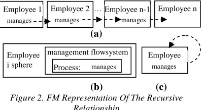
This type of recursive feature is represented in FM as shown in Figure 2(a), where “Employee i” is a sphere/flowsystem of a hierarchy of types of entities. Figure 2(b) shows a complete picture of each entity type, and Figure 2(c) shows a shorthand representation of the relationship.
In entity-relationship modeling, we sense the strain between the semantics of Employee as a person and his/her relationship to other persons, and what the data structure representation stands for
(as a record–a tuple–in a relational table with links to other records).
The E-R representation is a static link between two different types of nodes. In FM, semantically, Employee stands for a real element (sphere) that is defined by a process (flowsystem) called management where “management things” (e.g., regulation, instructions, …) flow. Other stages (transfer, release, …) and processing (besides manage) can be added.
In FM, the recurrence feature is modeled through the recurrence of manages by a process (sphere/flowsystem, since a sphere, in this example, contains a single flowsystem). That is, the sphere/flowsystem Employee is a process (not a static entity in the E-R model) that processes (manages) another process, and so forth. The result is a systematic conceptual picture of processes that process each other.
Consider the relationship among several massagers: a messenger who uses another messenger, who in turn uses another messenger, … For example, a visual metaphor is sometimes applied to the network communication process where computers, one after another, act as messengers. This can be represented as in Figure 3, where there is an actual flow (solid arrows) and not triggering as in Figure 2. Again, we see the systemization of a process (computer) that process (send to) another process.
Notice that, for simplicity’s sake, the flowsystems (of messages) and sphere (computer) are represented by one box.
Computer
Receive Transfer
[image:3.612.330.530.132.241.2]Release
Figure 3. Recursive Relationships Among Intermediate Computers
Employee 1 manages
Employee 2 manages
Employee n-1 manages
Employee n …
Employee
i sphere Process: manages management flowsystem
(a)
(b)
Figure 2. FM Representation Of The Recursive Relationship
Employee manages
[image:3.612.371.497.641.690.2]986
4. APPLYING FM CONCEPTUALIZATION
TO A RECURSION PROCESS I
In programming, the recurrence feature is applied to the method of solution (e.g., algorithm). A recursive problem solution clones itself, making new copies of the code and the local variables. This means:
1. The flow is a flow of methods, i.e., the flowthing is a method.
2. The flow system creates a copy of the method.
Consider the following famous factorial (n) algorithm:
Factorial (n) If n==1 return 1
else return n* factorial (n-1)
There are three elements embedded in the term factorial (n):
● Factorial as a method (algorithm)
● The value as global storage that holds the result, and
● The local variable n
The method and n form a sphere; let us call it (recursive) Step with its own version of the method and local variable n.
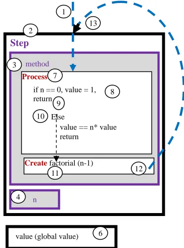
Accordingly, there are: a Step sphere that includes method and n, and a final value. The method is conceptualized as a flowthing that is received, transferred, processed, created, and released. The value and n are single flowsystem spheres, but for simplicity’s sake we draw them as boxes without internal details. Figure 4 shows the FM representation of the Factorial (n).
The execution starts with an outside triggering (circle 1) to process (7) or activate the method. We assume that the method is already received and residing in the system, waiting for execution. For example, in the context of a computer, the method is a program already loaded into memory, ready to be executed.
Activating process in method (circle 7) causes the evaluation of n; if it is zero, then (local) n is set to 1 (circle 8), and returned (9) to resume the execution in the parent method. Else (10), a new copy of the method and n (Step sphere) are created (11) and immediately activated (12 and 13).
We assume that creating a new step would freeze the current step waiting to be reactivated (9).
If we remove this assumption, we have to add “de-activating” indicators in the right places.
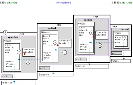
Creating and processing (activating) that form a step that includes a copy of the method and a local variable n, continues until n is equal to zero (the base of recursion). Figure 5 shows a sample calculation of 40. The execution proceeds according to the numbers in circles.
The FM provides a systematic representation of recursion instead of sketches of pictures and figures, typically used in teaching the concept. It is a framework that specifies flowsystems with creation and processing stages; thus, the base of recursion is a flowsystem that includes processing but does not include creation.
5. APPLYING FM CONCEPTUALIZATION
TO A RECURSION PROCESS II
To further demonstrate the FM methodology of modeling recursion, consider a traversal of a binary tree where each element of the binary tree is visited exactly once inorder as specified in the following.
Inorder(x)
if x = nil then return Inorder-Walk(left [x]) Print key[x]
Inorder-Walk(right[x]) Step
Process
Create factorial (n-1)
n
value == n* value return
value (global value)
if n == 0, value = 1, return
Else
method 2
3
4
6 7
8 9
11 12
10
[image:4.612.336.523.124.376.2]13
Figure 4. FM Representation Of The Factorial Solution
987 For example, for the binary tree shown in Figure 6, the inorder traversing is 2, 3, 4, 5, 6.
There are many software environments that support visual interface for recursive programs. For example, LabVIEW [26] uses block diagrams for a recursive algorithm with dragged icons. Figure 7 shows a sample screen view of a binary tree where “the value of the current node is compared with the new value until an empty child is found and it is inserted to the tree” [26]. The point of showing this methodology of visual representation of a binary tree is to demonstrate how such a professional application is built upon a collection of heterogeneous notions from data structures (e.g., tree), electrical schemata tools (e.g., inverter!), flowcharts, and so forth. These contrast with FM-based conceptual description constructed from spheres and flowsystems based on the notions of flow and triggering.
[image:5.612.97.527.73.346.2]Figure 8 shows a general FM model of the Inorder algorithm. First, the algorithm is triggered (circle 1) from outside, e.g., by an operating system as in the case of a program residing in main memory. Inorder is activated (processed) to call itself in left (2) and right (3). A recursive call means creating a copy of Inorder that is followed by processing (4 and 5).
Figure 7. The Value Of The Current Node Is Compared With The New Value Until An Empty Child Is Found And
Inserted Into The Tree (From [26]). step
Process
Create active factorial (3) if n == 1
value = 1, return Else
value == n* value Return
n = 4
method
step
Process
Create active factorial (2) if n == 1
value = 1, return Else
value == n* value Return
Figure 5. FM Representation Of Steps To Calculate Factorial 3
method step
Process
if n == 1 value = 1 return
method
value = 1 step
Process
Create active factorial (1) if n == 1
value = 1, return Else
value == n* value Return
method
n = 3
n = 2
n = 1
value = 2
value = 6
value = 24 1
2
3
4
5
6
7
8
Inorder(x)
Process: if x = nil then return Inorder(left [x]) Print key[x] Inorder(right[x])
create: Inorder(left [x])
Create: Inorder(left [x]) 1
2
3
[image:5.612.327.523.466.553.2]4 5
Figure 8. FM General Modeling Of Inorder Figure 6. Sample Binary Search Tree
0 3 0
left 6 0
0 5 0 0 2 right
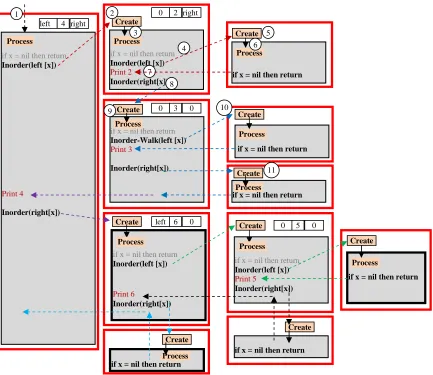
[image:5.612.318.530.610.702.2]988 Figure 9 shows an implementation of this algorithm for the binary tree shown in Figure 6. The execution starts at the root of the tree when the residing copy of the algorithm is activated (circle 1). Since the root is not nil, then Inorder(left [x]) is executed, causing the creation of a copy of Inorder (circle 2) with root of the sub-tree equal to 2.
Notice that no synchronization tool is incorporated into this description. It is assumed that the creation of a copy would “freeze” execution of the original execution waiting for a return from the call. FM description provides a basic conceptual map of flows and triggering; nevertheless, other tools such as synchronizations, timing, and logical operations (e.g., AND, OR) can be superimposed on the basic description.
Thus, based on our assumption, creating a copy (circle 2) is followed by processing of this copy (activating – circle 3).
This execution creates a copy of Inforder (circle 4) where the left links the root (circle 5). Executing (processing – circle 6) if x = nil then return causes continuation of the execution in the previous copy (7) where 2 is printed. The Inorder(right[x]) is executed (8), moving us to the sub-tree with root 3. The recursive process of creating and processing of copies continues for the left link (circle 10), and the right link (11) and so forth.
if x = nil then return
if x = nil then return Inorder(left [x])
Print 4
Inorder(right[x])
if x = nil then return Inorder(left [x]) Print 2
Inorder(right[x])
if x = nil then return Inorder-Walk(left [x]) Print 3
Inorder(right[x]) Process
Create
Create left 4 right
0 2 right
if x = nil then return Create
0 3 0 Create
if x = nil then return Create
if x = nil then return Inorder(left [x])
Print 6
Inorder(right[x]) Create left 6 0
if x = nil then return Inorder(left [x]) Print 5
Inorder(right[x]) Create 0 5 0
if x = nil then return Create
if x = nil then return Create
if x = nil then return Create Process
Process
Process
Process
Process
Process
Process Process
Process
1 2
3
4
5 6
7 8
9 10
[image:6.612.100.533.311.686.2]11
989
6. CONCLUSION
This paper introduces a conceptual model that provides a suitable representation for understanding the mechanics of recursion and assists in teaching and learning such a concept.
The model is analyzed using sample programs including factorial and binary tree traversing. The resulting conceptual picture points to the viability of the proposed methodology as an apparatus for understanding recursion. Further investigation aims at experimenting with the flow-based description of the recursive process in actual teaching environments.
REFERENCES:
[1] Turner, A. J. (1991). A summary of the ACM/IEEE-CS Joint Curriculum Task Force Report. Computing Curricula 1991. Communications of the ACM, 34(6), 69–84. [2] George, C. (2000). EROSI – Visualising
recursion and discovering new errors. In Proceedings of the 31st SIGCSE technical symposium on computer science education (pp. 305–309), Austin, Texas, USA.
[3] Wu, C., Dale, N., & Bethel, L. (1998). Conceptual models and cognitive learning styles in teaching recursion. In Proceedings of the 29th SIGCSE technical symposium on computer science education (pp. 223–227), Atlanta,
Georgia, USA.
http://www.it.uu.se/edu/course/homepage/datadi daktik/ht06/teaching/p292-wu-dell-bethel.pdf [4] Sooriamurthi, R. (2001). Problems in
comprehending recursion and suggested solutions. In Proceedings of the 6th annual conference on innovation and technology in computer science education (pp. 25–28), Canterbury, UK. ACM Press.
[5] Gotschi, T. (2003). Mental models of recursion. (Master’s thesis). University of the
Witwatersrand, Johannesburg.
ftp://ftp.cs.wits.ac.za/pub/research/reports/TR-Wits-CS-2004-1.pdf
[6] Levy, D., & Lapidot, T. (2000). Recursively speaking: analyzing students’ discourse of recursive phemomena. In Proceedings of the 31st SIGCSE technical symposium on computer science education (pp. 315–319), Austin, Texas, USA.
[7] Wiedenbeck, S. (1988). Learning recursion as concept and as a programming technique. SIGCSE Bulletin, 20(1), 275–278.
[8] Bhuiyan, S., Greer, J., & McCalla, G. (1994). Supporting the learning of recursive problem solving. Interactive Learning Environments, 4(2), 115–139.
[9] Er, M. C. (1984). On the complexity of recursion in problem-solving. International Journal of Man- Machine Studies, 20, 537–544. [10] Haberman, B., & Averbuch, H. (2002). The
case of base cases: why are they so difficult to recognize? Student difficulties with recursion. In Proceedings of the 7th annual conference on innovation and technology in computer science education (pp. 5–8), Aarhaus, Denmark. [11] Shih, Y. F., & Alessi, S. M. (1993). Mental
models and transfer of learning in computer programming. Journal of Research on Computing in Education, 26(2), 154–175. [12] Wilcocks, D., & Sanders, I. (1994). Animating
recursion as an aid to instruction. Computers and Education, 23(3), 221–226.
[13] Norman, D. A. (1983). Some observation of mental models. In D. Gentner and A. L. Stevens (Eds.), Mental models (pp. 7-14). Hillsdale, NJ: Erlbaum.
[14] Pirolli, P. L., & Anderson, J. R. (1985). The role of learning from examples in the acquisition of recursive programming skills. Canadian Journal of Psychology, 39, 240–272. [15] Mayer, R. E. (1988). Using conceptual models
to teach BASIC computer programming. Journal of Educational Psychology, 80(3), 291– 298.
[16] Dale, N. B., & Weems, C. (1991). Pascal (3rd ed.). Lexington, MA: D. C. Heath.
[17] Koffman, E. B. (1992). Pascal (4th ed.). Reading, MA: Addison Wesley.
[18] Aho, A. V., & Ullman, J. D. (1992). Foundations of computer science. New York: W. H. Freeman.
[19] Kessler, C. M., & Anderson, J. R. (1989). Learning flow of control: recursive and iterative procedures. In E. Soloway & J. C. Spohrer (Eds.), Studying the novice programmer (pp. 229-260). Hillsdale, NJ: Lawrence Erlbaum. [20] Greer, J. E. (1987). Empirical comparison of
techniques for teaching recursion in
introductory computer science. (Doctoral
dissertation). The University of Texas at Austin. [21] Al-Fedaghi, S., & AlZanaidi, D. (2012).
990 [22] Al-Fedaghi, S. (2011). Pure conceptualization
of computer programming instructions. International Journal of Advancements in Computing Technology, 3(9), 302–313.
[23] Al-Fedaghi, S. (2011). Awareness of context and privacy. American Society for Information Science & Technology (ASIS&T) Bulletin, 38(2).
[24] Al-Fedaghi, S. (2011). Information security management systems. Fifth Annual IFIP WG 11.10 International Conference on Critical Infrastructure Protection, Dartmouth College, Hanover, New Hampshire, USA, March 23–25. [25] Al-Fedaghi, S. (2012). Perceived privacy. IEEE
9th International Conference on Information Technology: New Generations, ITNG 2012, Las Vegas, Nevada, USA, April 16–18.