http://www.sciencepublishinggroup.com/j/ajme doi: 10.11648/j.ajme.20170305.12
Positive Streamer Simulation in Air Using Finite Element
Method
Abd Elatif El-Zein, Mohamed Talaat, Ashraf Samir
Electrical Power & Machines Department, Faculty of Engineering, Zagazig University, Zagazig, Egypt
Email address:
[email protected] (A. El-Zein), [email protected] (M. Talaat), [email protected] (A. Samir)
To cite this article:
Abd Elatif El-Zein, Mohamed Talaat, Ashraf Samir. Positive Streamer Simulation in Air Using Finite Element Method. American Journal of Modern Energy. Vol. 3, No. 5, 2017, pp. 95-100. doi: 10.11648/j.ajme.20170305.12
Received: August 20, 2017; Accepted: August 30, 2017; Published: September 26, 2017
Abstract:
A new methodology for positive streamer process is presented. This process depends on the critical electric field value that required for streamer initiation. So, an accurate computational of the electric field distribution across needle-to-plane gap is required. A finite element method using Comsol Multiphysics program is adopted for this simulation. The streamer path has been considered as a conducting path of 300 micro-meter in length and 30 micro-meter in radius with 108 electrons on its head. The results have been verified with others.Keywords:
Positive Streamer, Critical Electric Field, Needle-to-Plane, Finite Element Method1. Introduction
The electrical breakdown is an important electric phenomenon in dielectric materials. Conductors, in electrical equipment, are insulated by dielectric material in all three states to avoid flashover or short circuits between the parts of the electrical system with each other. Streamers are thin ionized filaments that break through a previously non-ionized region under the effect of an electric field. It is the pre-breakdown process and now became basically element in many electrical discharges. It is well-known that Streamers play important roles in production and growth of lightning channels. So, streamers have been strongly connected to development of lightning technology. In addition that is used for coating, powder formation and triggering fuel combustion in vehicle motors [1]. Nanosecond pulsed discharges are very operative in generating chemical radicals for the ignition of combustible mixtures too [2, 3].
The simulation methods are considered as one of the most suitable methods for studying the discharge process; there is several simulation methods used, with needle-to-plane configurations. Finite difference method (FDM), is a numerical method, is used for solving differential equations by approximating converting them into difference equations with many grid points. But, this method can only be applied on the uniform field gap [4-8]. Boundary element method (BEM) is a numerical computational method of solving linear
partial differential equations which, is based on the integral of the boundary to achieve the controlling differential equation [7, 9].
It can be applied on many areas of engineering and science including fluid mechanics, acoustics, and electromagnetics. So, the surface of the problem domain is only needed to be modelled.
Charge simulation method (CSM) [7, 10-16], is used for simulation of the electric field by several discrete number of imaginary charges which are existed inside the conductors. These charges are determined at several selected contour points at the conductor surfaces by satisfying the boundary conditions. All these charges are determined; the simulated electric field can be evaluated at any point around the conductors by using the principle of superposition. Finite element Method (FEM) is using the mesh generation techniques for distributing a complex problem to small elements so as to solve the problems according to boundary conditions [5, 7, 17-20].
FEM is used for detecting the solutions of the electric field distribution which satisfy the boundary conditions using partial differential equations. FEM can be suitable for complex configurations of the streamer systems progress in any case of the electrode shape, medium gases, volume of charges, and gap length.
of space charge [21-23]. The 1.5-D equilibrium fluid model have been studied by Davies et al [24], Yoshida and Tagashira [25], and Morrow [26] for the electric breakdown observation in gases with the spatial temporal development of ionization. In the work by [27], a local discontinuous Galerkin method for the 1.5-dimensional streamer discharge simulations is proposed. The required electric field value for streamer initiation is 4.5 5 kV/cm [28-33], considering fair atmospheric conditions of 1013 and 293 at a humidity of 11 under impulse voltage supply of
1.2 50⁄ as given by [28]. From the previous experimental
results [30, 31, 33] the critical electric field requires a velocity of ≅ 10! / .
In this work, a simulation study of the streamer methodology process has been investigated using a simplified needle-to-plane will be used which is consisted of needle protrusion bar for anode and disc plane structured for from a copper. The concept of FEM has been used which depend on partial differential equations (PDE) solutions by COMSOL Multiphysics program. The steps of the gap will be 30 for each step of the streamer progress. For the streamer initiation, the applied electric field is selected from mentioned references to be 4.5 "#/$ and for each step of the streamer there is 10% electrons distributed at the streamer tip. The simulation results have been investigated with previous theoretical and experimental result given by others.
2. Method of Analysis
The model of streamer inception is based on the accumulation of successive individual avalanches when reach to the critical size. The avalanches all contain 10% electron and start from photoelectrons produced in the gas by photons emitted from the avalanche region by secondary effects [33].
2.1. Critical Avalanche Size
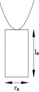
The model considers the avalanche as cylindrical shape shows Figure 1. So, the volume size of individual avalanche can be evaluated according to Equation (1).
&'() * + , -.(- ( 1) where, - and (- is a radius and length of the avalanche.
Figure 1. The avalanche model with cylindrical geometry.
So, the electron density (/0) in each avalanche is calculated from Equation (2).
/0+3145264 (2)
where, 70 is the number of electrons.
If the avalanche grows with velocity &- through time 8, the length (- can be written
(-+ &-∗ 8 (3) and
8 + 45
:; (4)
where, D is the electron diffusion coefficient.
By using Equation (2, 3, 4), the radius of avalanche is
-+ 3<:;14=22 >/: (5)
But the number of electrons in avalanche can be evaluated from the following Equation (6)
70+ *∝@ (6)
where, ∝ is Townsend’s first ionization coefficient, A is the distance gap. For the streamer condition, the value of ∝ A ranges from 18 8' 20 [34].
From spectroscopic measurements, the diffusion coefficient is C + 16800 $ .. > [32] and {/0+ 6 ∗
10>: $ [32], &-+ 2 ∗ 10E $ / and the minimum
∝ A + 18}. According to the previous values the radius of primary streamer equal+ 0.0032 $ ≅ 30 . This result corresponds with more of experimental and modelling works.
2.2. Mathematical Model
The electric field intensity (E) can be evaluated at (each streamer step), by using Poisson’s Equation [35] as follow;
G.U + IJ
K (7)
where, L< is the volume charge density in M⁄ , N is the potential in each point between the two electrodes at the surrounding domain in Volt V ,, and O is the dielectric permittivity (in air, O ≅ OP is approximately the vacuum dielectric permittivity of 8.854 Q 10 >.F/m)
∴ G ∙ UOP GU V + L< (8)
But, the value of the electric field intensity, can be given as;
+ GU V m⁄ (9) The boundary condition between the two electrodes, surrounding domain, for FEM analysis satisfies the Poisson’s equation.
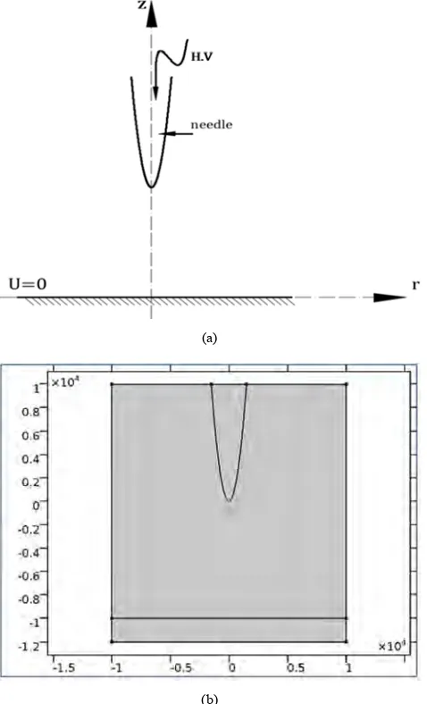
two electrodes given by a certain value of the applied voltage, at the needle U + #, and the plane U + 0 as Figure 2.
(a)
(b)
Figure 2. (a) needle-to-plane model, (b) A schematic diagram using Comsol Multiphysics program.
In 3-D dimensions, the electric field intensity is calculated in terms of the variation of the electrical potential as:
+ WXYX Z XYX[ [ZX\X] ]^ (11)
But, in 2-D modeling, due to the geometry are axially symmetric, the variation of the potential in the angle rotational direction (_ direction) is considered as zero, (`N `_⁄ + 0). Also, the value of the volume charge density will be taken per unit length and considered as surface charge density, La, uniformly distributed along the circular base area of the streamer head.
∴ G ∙ OP + La (12)
where, the electric field intensity in 2-D is given as,
+ WX\X ZX\X] ]^ (13)
At the streamer head of each step, many charges, La, have been produced. These charges generate an external electric field. The streamer can be initiated when the field at the head or at each advanced streamer head approaches the critical electric field, which equals 4.5 "#/$ [29, 36]. According to the Meek's criterion of streamer initiation, the number of electrons for streamer inception is nearly 10% electrons [37-40].
Thus, the surface charge density of 10% electrons is given as,
Lb+ *70 (14) where, * is the charge of electron, 70 is the number of electrons.
3. Results and Discussions
3.1. Needle to Plane Simulation
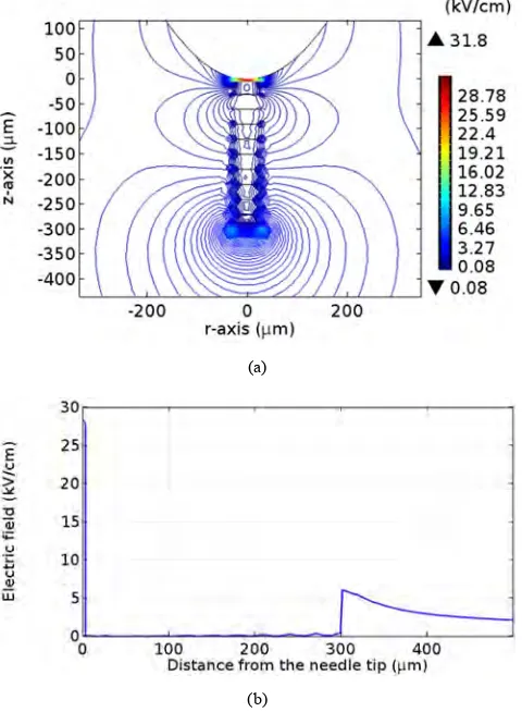
The simulation results of the distribution of the electric field across the needle-to-plane gap are given in Figure 3.
Figure 3. The simulation of the electric field along the gap.
Figure 4. Electric field distributions along z-axis using FEM.
Figure 3, shows that the stressed zone is around the needle tip with a field value of 4.5 "#/$ which is required for the streamer initiation.
3.2. Streamer Inception Simulation
Figure 5, is represented the simulation methodology of streamer inception which is distributed 10% electrons at each step of the streamer head. This figure represents the development and growth of the streamer through ten stages in the stressed volume zone, which is given as 300 [41] through the needle-to-plane gap.
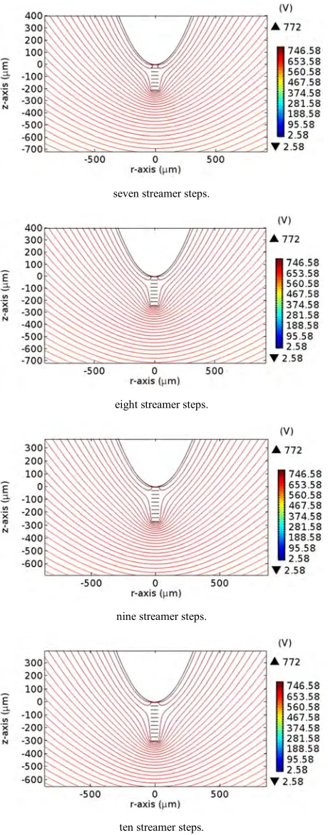
Also, the distributions of the electric potential along the vertical steps of the streamer propagation through the stressed volume zone obtained from Comsol Multiphysics program. Figure 6, explains that the region between the needle through streamer path is nearly conducting, which is considered as a characteristic and a boundary condition of stressed/ quasi-conducting zone [35].
(a)
(b)
Figure 5. (a) The simulation of the electric field for streamer progress, (b) Electric field distributions along the gap axis Voltage Distribution.
one streamer step
two streamer steps
three streamer steps
four streamer steps
five streamer steps
seven streamer steps.
eight streamer steps.
nine streamer steps.
ten streamer steps.
Figure 6. The simulation of the potential distribution as a contour lines around the needle tip in the locating of surface charges for ten stages streamer progress.
4. Conclusions
The previous simulation results give the methodology to the streamer progress. After accurate field simulation, the
following points can be illustrated as follow:
1. The critical electric field required for streamer initiation is 4.5 "#/$ .
2. The length of the streamer step and the radius of the streamer filament is approximately equal to 30 . 3. A value of 10% electrons at streamer tip is required for
obtaining the critical electric field value at each streamer propagation step.
4.The path of streamer is represented a quasi-conducting path.
References
[1] J.-P. Borra, "Nucleation and aerosol processing in atmospheric pressure electrical discharges: powders production, coatings and filtration," Journal of Physics D: Applied Physics, vol. 39, p. R19, 2006.
[2] A. Y. Starikovskii, N. B. Anikin, I. N. Kosarev, E. I. Mintoussov, M. M. Nudnova, A. E. Rakitin, et al., "Nanosecond-pulsed discharges for plasma-assisted combustion and aerodynamics," Journal of Propulsion and Power, vol. 24, pp. 1182-1197, 2008.
[3] S. V. Pancheshnyi, D. A. Lacoste, A. Bourdon, and C. O. Laux, "Ignition of propane–air mixtures by a repetitively pulsed nanosecond discharge," IEEE Transactions on Plasma Science, vol. 34, pp. 2478-2487, 2006.
[4] A. Kulikovsky, "Two-dimensional simulation of the positive streamer in N2 between parallel-plate electrodes," Journal of Physics D: Applied Physics, vol. 28, p. 2483, 1995.
[5] W.-G. Min, H.-S. Kim, S.-H. Lee, and S.-Y. Hahn, "An investigation of FEM-FCT method for streamer corona simulation," IEEE transactions on magnetics, vol. 36, pp. 1280-1284, 2000.
[6] X. Wang, F. Wang, W. Pfeiffer, and N. Kouzichine, "Simulation of Two-Dimensional Streamer Discharge in Uniform Field in Low SF 6 Content Mixtures," in Electrical Insulation, 2008. ISEI 2008. Conference Record of the 2008 IEEE International Symposium on, 2008, pp. 324-326.
[7] M. N. Sadiku, Numerical techniques in electromagnetics 2nd ed.: CRC press, 2001.
[8] H. MENGMIN, "Numerical Methods and Comparison for Simulating Long Streamer Propagation," 2014.
[9] A. Peyda, "Numerical and experimental investigation to determine corona inception electric field for rod-plane electrode configuration," in Masters Abstracts International, 2006. [10] L. F. Fouad, M. Abdel-Salam, A. G. Zeitoun, and M. K. Gohar,
"Performance Characteristics of Alpha-Particle Corona-Streamer Counter," IEEE Transactions on Industry Applications, pp. 510-515, 1978.
[11] M. Abdel-Salam and M. El-Mohandes, "Combined method based on finite differences and charge simulation for calculating electric fields," IEEE Transactions on Industry Applications, vol. 25, pp. 1060-1066, 1989.
[13] M. El-Bahy, M. Abouelsaad, N. Abdel-Gawad, and M. Badawi, "Onset voltage of negative corona on stranded conductors," Journal of Physics D: Applied Physics, vol. 40, p. 3094, 2007.
[14] M. Gaber, M. Trlep, and B. Štumberger, "Successful 3D simulation of branching streamer in air bridging the gap between main electrodes using charge simulation method," in Electromagnetic Field Computation (CEFC), 2010 14th Biennial IEEE Conference on, 2010, pp. 1-1.
[15] L. Arevalo, V. Cooray, D. Wu, and B. Jacobson, "A new static calculation of the streamer region for long spark gaps," Journal of electrostatics, vol. 70, pp. 15-19, 2012.
[16] M. Talaat, "Electrostatic field calculation in air gaps with a transverse layer of dielectric barrier," Journal of Electrostatics, vol. 72, pp. 422-427, 2014.
[17] G. Georghiou, R. Morrow, and A. Metaxas, "Two-dimensional simulation of streamers using the FE-FCT algorithm," Journal of physics D: Applied physics, vol. 33, p. L27, 2000.
[18] H.-J. Ju, H.-D. Hwang, J.-H. Park, and K.-C. Ko, "2-dimensional simulation of corona discharge using FEM-FCT method in wire-cylinder reactor," in Plasma Science, 2003. ICOPS 2003. IEEE Conference Record-Abstracts. The 30th International Conference on, 2003, p. 290.
[19] O. Eichwald, O. Ducasse, D. Dubois, A. Abahazem, N. Merbahi, M. Benhenni, et al., "Experimental analysis and modelling of positive streamer in air: towards an estimation of O and N radical production," Journal of Physics D: Applied Physics, vol. 41, p. 234002, 2008.
[20] A. Luque and U. Ebert, "Density models for streamer discharges: beyond cylindrical symmetry and homogeneous media," Journal of Computational Physics, vol. 231, pp. 904-918, 2012.
[21] R. Morrow, "Theory of negative corona in oxygen," Physical Review A, vol. 32, p. 1799, 1985.
[22] N. Aleksandrov and E. Bazelyan, "Simulation of long-streamer propagation in air at atmospheric pressure," Journal of Physics D: Applied Physics, vol. 29, p. 740, 1996.
[23] V. Shveigert, "Ionization wave at streamer gas breakdown. Driftdiffusion approximation," Teplofiz. Vys. Temp, vol. 28, pp. 1056-1063, 1990.
[24] A. Davies, C. Evans, and F. L. Jones, "Electrical breakdown of gases: the spatio-temporal growth of ionization in fields distorted by space charge," in Proceedings of the Royal Society of London A: Mathematical, Physical and Engineering Sciences, 1964, pp. 164-183.
[25] K. Yoshida and H. Tagashira, "Computer simulation of a nitrogen discharge at high overvoltages," Journal of Physics D: Applied Physics, vol. 9, p. 491, 1976.
[26] R. Morrow, "Properties of streamers and streamer channels in SF 6," Physical Review A, vol. 35, p. 1778, 1987.
[27] C. Zhuang and R. Zeng, "A local discontinuous Galerkin method for 1.5-dimensional streamer discharge simulations," Applied Mathematics and Computation, vol. 219, pp. 9925-9934, 2013.
[28] I. Pub, "60-1, “High-voltage test techniques, Part 1: General definitions and test requirements”," International Electrotechnical Commission, International Standard, 1989.
[29] Y. P. Raizer and J. E. Allen, Gas discharge physics vol. 2: Springer Berlin, 1991.
[30] J. Qin and V. P. Pasko, "On the propagation of streamers in electrical discharges," Journal of Physics D: Applied Physics, vol. 47, p. 435202, 2014.
[31] N. Allen and A. Ghaffar, "The conditions required for the propagation of a cathode-directed positive streamer in air," Journal of Physics D: Applied Physics, vol. 28, p. 331, 1995.
[32] F. Bastien and E. Marode, "The determination of basic quantities during glow-to-arc transition in a positive point-to-plane discharge," Journal of Physics D: Applied Physics, vol. 12, p. 249, 1979.
[33] A. Kulikovsky, "The role of photoionization in positive streamer dynamics," Journal of Physics D: Applied Physics, vol. 33, p. 1514, 2000.
[34] D. Kind and H. Kärner, High-voltage insulation technology vol. 621: Springer, 1985.
[35] W. H. Hayt and J. A. Buck, Engineering electromagnetics vol. 7: McGraw-Hill New York, 2001.
[36] A. Fridman and L. A. Kennedy, Plasma physics and engineering: CRC press, 2004.
[37] L. B. Loeb and J. M. Meek, "The mechanism of spark discharge in air at atmospheric pressure. I," Journal of Applied Physics, vol. 11, pp. 438-447, 1940.
[38] H. Raether, "Electron avalanches and breakdown in gases," 1964.
[39] G. Dawson and W. P. Winn, "A model for streamer propagation," Zeitschrift für Physik, vol. 183, pp. 159-171, 1965.
[40] I. Gallimberti, "A computer model for streamer propagation," Journal of Physics D: Applied Physics, vol. 5, p. 2179, 1972.