ABSTRACT
NEEDHAM, ERINN CHRISTINE. Atomic Layer Deposition for the Modification and Creation of Nanomaterials. (Under the direction of Dr. Gregory N. Parsons).
Atomic layer deposition (ALD) is a vapor-phase technique for the conformal deposition of material with sub-nanometer precision, making it an ideal process for modifying and even creating nanomaterials. The focus of this dissertation is the study of how ALD precursors interact with organic materials, namely polymers, to create selectively deposited nano-scale patterns and how ALD coatings modify biological responses to nanomaterials, namely carbon nanotubes (CNT), after inhalation.
Nanoscale patterning is vital to the semiconductor industry. With features becoming smaller and more complex with each passing year, new techniques are required to meet the needs of the industry. The ability to selectively pattern a material onto a wafer is of particular interest for the replacement of costly etching steps.
In the first half of this dissertation, a method for the selective deposition of nano-scale patterns is presented. Patterned polymers were used as sacrificial sponges to soak up ALD precursors for the creation of metal-oxide features. Meanwhile, deposition in areas without polymer was limited to the monolayer regime. Following infiltration, the saturated polymer was burned away and the precursor oxidized to form a metal oxide reproduction of the polymer pattern. Determining the reaction between the ALD precursor, trimethylaluminum, and polymer, poly(methyl methacrylate), helped to achieve patterning by informing the proper selection of reactor temperature as well as exposure and purge times. Using this technique, features from tens of nanometers to tens of microns were patterned uniformly and simultaneously across a 150 mm wafer.
selectively deposit the second material. By patterning two materials from one patterned polymer, no pattern alignment between materials is necessary.
The reaction mechanism determined for this system can be applied and expanded to other vapor-phase metal-organic interactions with polymers. The ability to make and align nanoscale features is critically important for manufacturing improved semiconductor devices.
The second half of this dissertation focuses on how modification of CNT affects biological response in a material-dependent manner. CNT have unique physical and chemical properties that lead to applications in many areas including: electronics, high-strength materials, filtration and drug delivery. By surface-modifying these materials, a whole new realm of applications appears.
Despite the benefits these coatings may provide (e.g., photocatalytic properties and increased conductivity) they can also alter the toxicological response to MWCNT. In rodent models, the inhalation of MWCNT can lead to inflammation and fibrosis. Here, we observed that ZnO coatings on MWCNT led to an acute inflammatory response but did not change the fibrotic response in mice following inhalation.
The contribution of ZnO coating dissolution was still unknown following the in vivo study with mice. Alumina, ZnO and aluminum-doped ZnO (AZO) coatings on MWCNT were studied in vitro using various cell lines to determine the contribution of ions to toxicity. AZO is less soluble than ZnO and composed only of previously-characterized materials.
Atomic Layer Deposition for the Modification and Creation of Nanomaterials
by
Erinn Christine Needham
A dissertation submitted to the Graduate Faculty of North Carolina State University
in partial fulfillment of the requirements for the degree of
Doctor of Philosophy
Chemical Engineering
Raleigh, North Carolina 2016
APPROVED BY:
_______________________________ _______________________________
Dr. Gregory N. Parsons Dr. James Bonner
Committee Chair
_______________________________ _______________________________
DEDICATION
To all those that came before me, without whom the tools necessary to complete this would not exist.
To my teachers, both in an out of school, for my understanding of the world around me. To my parents for always answering my questions, teaching me to solve problems, and
having the patience to do the first two.
BIOGRAPHY
Erinn Christine was born to Sean and Jayne Dandley; two wonderfully weird, supportive and generally bad ass parents; in 1989. She has one brother, Michael, who has been taller and more patient than her since he was two and she was four. Throughout her life she has picked up many random skills from a diverse cast of characters that have led her to being able to complete this body of work. The Dandley’s are quite hands on problem solvers that aren’t afraid to get dirty. From a young age Erinn would help out with projects around the house with the aid of her parents. By middle school she could solve most problems with a roll of duct tape.
Stubborn and fiercely independent she sometimes needed guidance from one brave soul or another. In one such instance it was gently suggested to her that she join track and field in high school. After deciding she hated running she specialized in short sprints, javelin and pole vault. Her pole vaulting career continued at the University of Massachusetts-Amherst where both her parents and her brother went to college. Pole vaulting introduced her to some of her best longtime friends and travel companions.
Throughout school Erinn showed a propensity for math and science. Challenged with a tough chemistry teacher in high school she learned a serious amount of material on the subject. This led her father to suggest a major in chemical engineering at UMass after a year of entrepreneurial studies.
After searching far and wide for the school that fit her best, remember she is stubborn, she decided on NC State, which was really great because Craig was already there studying for his PhD. There she pursued her PhD in chemical and biomolecular engineering under Dr. Greg Parsons. She was also fortunate to be co-advised by Dr. Bonner in toxicology and Dr. Chang in mechanical engineering.
ACKNOWLEDGMENTS
I sincerely thank my parents for creating me as well as teaching me to fix things, question “known” answers, and be an independent person in the world. I thank my brother for forgiving me for being the oldest and for making the world a more beautiful place. I also thank all of my new Needham family for their support and encouragement as well as making me feel so welcome.
My advisor, Greg Parsons, I would like to thank for his encouragement to follow hunches, be creative, explore how things work, and collaborate with people with different specialties. Through his guidance I have greatly increased my research proficiency. I would also like to thank Dr. Chang for expanding my knowledge in material science and applying my research to real life applications. I would like to thank Dr. Bonner for his excellence in scientific storytelling and for allowing me to continue to explore the biological realm.
I also thank all of the friends that I have made during my time here; you all have made Raleigh such a wonderful place to live and have contributed immensely to the establishment of my work-life balance. I would also like to thank my lab mates and collaborators for their support and assistance. Without you I would not have been able to finish this degree.
TABLE OF CONTENTS
LIST OF TABLES ... XI LIST OF FIGURES ... XII
CHAPTER 1. INTRODUCTION ... 1
1.1 Atomic layer deposition (ALD) ... 1
1.2 ALD modifications... 2
1.3 Nanopatterning via infiltration ... 4
1.3.1 Selective deposition ... 4
1.3.2 Infiltration of ALD precursors ... 5
1.3.3 Brief summary of results ... 6
1.4 Modified nanomaterials and the lung ... 8
1.4.1 Pulmonary fibrosis and inflammation ... 9
1.4.2 Nanoparticle-lung interaction following inhalation ... 10
1.4.3 MWCNT uses and current research ... 11
1.4.4 ZnO uses and current research ... 12
1.4.5 AZO uses and current research ... 16
1.4.6 Brief summary of results ... 17
CHAPTER 2. TEMPERATURE-DEPENDENT REACTION BETWEEN TRIMETHYLALUMINUM AND POLY(METHYL METHACRYLATE) DURING SEQUENTIAL VAPOR INFILTRATION: EXPERIMENTAL AND AB INITIO ANALYSIS ... 20
2.1 Introduction ... 20
2.2 Experimental procedures ... 21
2.2.2 Sequential vapor infiltration (SVI)... 22
2.2.3 Characterization ... 22
2.2.4 Quantum chemistry analysis ... 23
2.3 Results ... 24
2.3.1 In situ FTIR and QCM ... 24
2.3.2 Quantum chemical analysis ... 29
2.3.3 Observed chromatic shift ... 33
2.4 Discussion ... 34
2.5 Summary ... 37
2.6 Acknowledgements ... 37
CHAPTER 3. WAFER-SCALE SELECTIVE-AREA DEPOSITION OF NANOSCALE METAL OXIDE FEATURES USING VAPOR SATURATION INTO PATTERNED POLY(METHYL METHACRYLATE) TEMPLATES ... 38
3.1 Introduction ... 38
3.2 Results and Discussion ... 41
3.2.1 Polymer Saturation and Metal Oxide Thickness ... 41
3.2.2 Patterning and Area Selectivity ... 45
3.2.3 Metal Oxide Film Composition, and Extent of TMA Adsorption in PMMA ... 47
3.2.4 Effect of Infiltration Temperature on Vapor/Polymer Interaction and Saturation ... 48
3.2.5 Film Density vs Anneal and Post–Processing Treatment ... 50
3.2.6 Selectivity Scaling and Large-Area Uniformity ... 52
3.3 Conclusion ... 55
3.4.1 Chemicals and Materials ... 56
3.4.2 Polymer Patterning ... 56
3.4.3 Saturated Vapor Infiltration ... 57
3.4.4 Characterization ... 57
3.5 Acknowledgements ... 58
CHAPTER 4. PAIRED SELECTIVE DEPOSITION FOR THE CO-PATTERNING OF TWO DIELECTRICS FROM ONE PATTERNED PHOTORESIST ... 59
4.1 Introduction ... 59
4.2 Methods ... 61
4.2.1 Chemicals and Materials ... 61
4.2.2 Polymer Patterning ... 61
4.2.3 Atomic Layer Deposition ... 61
4.2.4 Vapor Infiltration ... 62
4.2.5 Characterization ... 62
4.3 Results and Discussion ... 63
4.3.1 Zinc oxide deposits selectively in PMMA-free regions ... 63
4.3.1 Selective TMA infiltration into PMMA is not inhibited by prior ZnO/water ALD cycles ... 64
4.3.2 Titania deposits selectively in PMMA free regions ... 66
4.3.3 Alumina deposits as a monolayer on titania ALD but not ZnO ALD during infiltration ... 68
4.3.4 Other ALD precursors tested ... 70
4.4 Conclusions ... 70
CHAPTER 5. ATOMIC LAYER DEPOSITION COATING OF CARBON NANOTUBES WITH ZINC OXIDE CAUSES ACUTE PHASE IMMUNE RESPONSES IN HUMAN MONOCYTES IN VITRO AND IN MICE AFTER PULMONARY
EXPOSURE ... 72
5.1 Background ... 72
5.2 Results ... 74
5.2.1 ALD on MWCNTs creates a conformal layer of ZnO that modifies physical properties ... 74
5.2.2 Z-MWCNTs stimulate pro-inflammatory cytokine expression by THP-1 cells in vitro ... 78
5.2.3 ZnO coating enhances the acute lung inflammatory response to MWCNTs in mice ... 80
5.2.4 ZnO coating prevents MWCNT uptake in the lungs of mice ... 83
5.2.5 ZnO coating of MWCNTs increases the acute phase lung inflammatory response in mice but does not affect the chronic pulmonary fibrotic response ... 83
5.2.6 ZnO coating prevents MWCNT-induced DNA synthesis in airway epithelium of mice ... 84
5.2.7 ZnO coating of MWCNTs increases pro-inflammatory cytokines in the lungs of mice ... 85
5.2.1 Pulmonary exposure to ZnO-coated MWCNTs induces a systemic increase in IL-6 mRNA ... 8IL-6
5.3 Discussion ... 87
5.4 Conclusions ... 95
5.5 Methods ... 96
CHAPTER 6. ALUMINUM DOPING OF ZNO COATINGS ON MULTI-WALLED CARBON NANOTUBES ALTERS THE COATING DISSOLUTION AS WELL AS CELL TYPE DEPENDENT CYTOTOXICITY AND CYTOKINE PRODUCTION . 102
6.1 Common Abbreviations ... 102
6.2 Background ... 103
6.3 Results ... 106
6.3.1 MWCNT Characterization ... 106
6.3.2 ALD coating dissolution and pH dependence ... 109
6.3.3 Cell type dependent dissolution of ZnO ... 110
6.3.4 Cellular uptake of MWCNT in the THP-1 cell line... 112
6.3.5 Cell type dependent cytotoxicity mirrors Zn2+ release ... 114
6.3.6 IL-1 protein release was dependent on cell type and MWCNT coating ... 116
6.4 Discussion ... 118
6.5 Summary ... 124
6.6 Methods ... 125
6.7 Acknowledgements ... 129
REFERENCES ... 130
APPENDICES ... 145
LIST OF TABLES
Table 2.1. Experimental, calculated and adjusted IR peak positions for methyl trimethylacetate as a model for PMMA. Experimental and calculated peak positions are also shown for the starting material after exposure to trimethylaluminum. ... 32
Table 4.1. XPS results for co-patterned sample with ZnO and Al2O3 regions. Atomic percent
rounded to the nearest whole number. < 0.05 % indicates the element was below the detection limit of the XPS. ... 65
Table 4.2. XPS results for co-patterned sample with TiO2 and Al2O3 regions before and after a
nitric acid etch. Atomic percent rounded to the nearest whole number. < 0.05 % indicates the element was below the detection limit of the XPS. ... 68
Table 6.1. Significance data for Zn2+ release when comparing all cell types. * denotes P<0.05, ** denotes P<0.01, *** denotes P<0.001, and NS denotes not significant. ... 112
LIST OF FIGURES
Figure 1.1. Outline of atomic layer deposition (ALD), a set of two self-limiting half reactions leading to growth of one monolayer of material at a time. The reaction between diethylzinc (DEZ) and water are depicted here to deposit zinc oxide (ZnO). ... 1
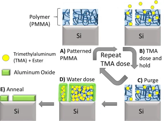
Figure 1.2. Outline of selective infiltration using trimethylaluminum (TMA) to pattern alumina. A) Infiltration starts with a patterned polymer on a silicon wafer. B) TMA gas is introduced to the system and held in the reactor to allow for diffusion and reaction to occur throughout the polymer bulk. C) The reactor is purged to remove unreacted TMA and byproducts. Steps 1-3 are repeated as many times as desired until D) one water dose, with no hold step, is introduced to form an oxide layer to trap in TMA. Samples were then removed from the reactor and E) heated rapidly in a furnace open to air to burn off the polymer, react the TMA with atmospheric water and anneal the product into a solid alumina layer. ... 2
Figure 1.3. Outline of ALD coating on MWCNT. 1) MWCNT are loaded into a mesh basket surrounded by nonwoven polypropylene (PP) and placed into an ALD reactor. 2) DEZ is dosed and held in the reactor and then 3) purged. 4) Water is then dosed into the reactor and held followed by 5) another purge. This can be repeated as many times as desired to coat the CNT with a thin film of ZnO, in the case described, or other materials. ... 3
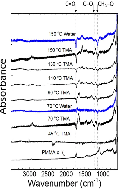
Figure 2.1. In situ FTIR spectra collected after 150 TMA doses on 170 nm thick PMMA films on silicon. The spectra are shown in differential mode, relative to the starting PMMA. Two spectra collected after TMA + water at 70 and 150 °C are also included, and similarly referenced to the starting PMMA. ... 25
Figure 2.2. (a) Overall QCM mass response for 50 nm PMMA films exposed to 100 TMA doses at 70, 100 and 140 °C. (b) Magnified view of the mass response after 41-43 TMA doses. ... 27
shows different reaction trends at different temperatures, most noticeably in the region between 1500 and 1700 cm-1. ... 29
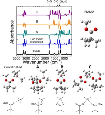
Figure 2.4. Relaxed chemical structures calculated using ab initio modeling, and their corresponding vibrational spectra referenced to spectra from structures calculated without TMA interaction. The bond models used for the calculations are also shown. The calculated spectrum for the PMMA model shows peaks at 1790 cm-1 corresponding to C=O stretch, and features at 1307, 1212 and 1182 cm-1 associated with =C-O- and -O-CH
3 coupled modes. For
each structure, interaction with TMA leads to loss of the 1790 cm-1 C=O mode and changes in
the C-O vibrations. The peak at 1725 cm-1 is TMA coordinated to the C=O in a physisorbed state, and is consistent with the IR and QCM results at lower temperature. Peaks between 1750 and 1500 cm-1 in products B and C correspond to C=O coordinated with a neighboring covalently-bound Al-O, forming a resonant C=O∙∙∙Al-O-C unit, consistent with the higher temperature product mode observed at 1568 cm-1. ... 31
Figure 2.5. Bulk PMMA powder, as received, was treated with 600 TMA doses at varying temperatures. At increased temperatures a color change was observed that was not seen at lower temperatures. A) PMMA powder as received. B) PMMA powder with 600 SVI TMA doses at 90°C. C) PMMA powder with 600 SVI TMA doses at 150°C immediately after removal from the reactor, after D) 1.5 hrs E) 24 hrs and F) 9 months. ... 34
Figure 2.6. Proposed pericyclic activation of ester to form metal acetate. ... 37
Figure 3.1. Schematic of a polymer film saturated by vapor infiltration followed by oxidation. The nano-patterned polymer is saturated with a precursor through extended exposure. Once infiltrated, the sample is annealed to remove the polymer, and oxidize the precursor to create a nano-patterned dielectric material that precisely mimics the starting pattern across a large surface area. ... 39
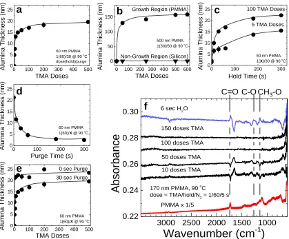
500 oC. A) Increasing TMA doses leads to a saturating alumina thickness after 100 TMA doses. B) Thick alumina films can be achieved while maintaining a non-growth surface. C) Altering the hold time of TMA in the reactor led to increased growth per dose. D) Altering the purge time of each TMA dose led to decreased growth per dose. E) By removing the purge from each TMA dose thick films were grown rapidly but with increased variability. F) In situ infrared spectra show polymer saturation after 50 TMA doses, the formation of a Lewis-acid base adduct between the PMMA ester and TMA at 1670 cm-1, and the partial reversion of this adduct
after water exposure (scans shown in differential form show the difference of one spectra from the one below it)... 43
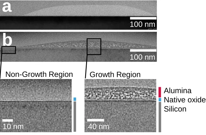
Figure 3.3. XTEM images of starting PMMA and resulting alumina films formed at 90 oC. A) Patterned PMMA 30 nm thick. B) 100 TMA doses into 60 nm PMMA led to 19 nm of alumina following the anneal step, whereas the region without PMMA shows only native oxide present. Film thicknesses are consistent with ellipsometry in Figure 3.2. In the TEM images, the variable contrast in the deposited metal oxide layer is consistent with uniform film porosity. ... 45
Figure 3.4. XPS data shows the elemental differences between the growth (PMMA) and non-growth (silicon) regions of a 2 cm2 silicon substrate that was half coated with 500 nm of PMMA. The sample was infiltrated with 500 TMA doses at 90 oC and annealed at 500 oC. Significantly less alumina was seen on the non-growth region. Following a 1 hour 0.01 M nitric acid etch there was no detectable alumina on the non-growth region while the growth region remained unchanged. ... 46
Figure 3.5. The effect of exposure temperature on alumina thickness. Lines meant to guide the eyes. Recipe: Dose(hold)/purge x number of repeated doses, time in seconds. All samples annealed at 500 oC unless otherwise noted. A) Increased TMA exposure caused alumina
saturation. B) Zoomed in view of Figure 3.5a highlights up to 50 TMA doses. C) A linear relationship between PMMA thickness and alumina thickness was observed. Exposure at 90
alternating between TMA, and water without full reactant saturation, no PMMA thickness dependence was observed. D) The infiltration temperature was altered from 45 to 150 oC using both 5 and 200 TMA doses. Temperatures higher than the glass transition temperature (Tg = 95 oC) show thinner films in both cases, whereas the low temperature films grew thicker with increased TMA dosing. E) Increased annealing temperature and time led to increased alumina refractive index, directly proportional to density. ... 50
Figure 3.6. PMMA was patterned with an electron beam, saturated with TMA and then annealed to alumina. a,b) SEM micrographs of patterned PMMA and the resulting alumina pattern, respectively, show high fidelity in pattern transfer. c) SEM micrograph of patterned PMMA, top, and the resulting alumina, bottom, show the pattern shrinking 33% from 30 to 20 nm following sub-saturating infiltration and anneal. d) Varying the TMA dose controlled the width of the patterned alumina. The original PMMA feature width was 188 nm. e,f) SEM of patterned alumina. g) Side view of alumina film on silicon. h) SEM micrograph of patterned titanium dioxide. In all plan view micrographs patterns through to the silicon substrate are the lighter color except (c) where charging of the nonconductive alumina caused it to appear lighter. i) A 300 nm wide PMMA line (200 nm thick) treated with 200 TMA/water ALD cycles with extended exposures (left) and 200 TMA doses (right). ... 52
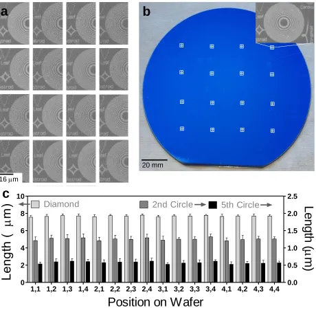
Figure 3.7. A 150 mm wafer was patterned using electron beam lithography to determine process scalability. A 200 by 200 m pattern was applied in groups of 4 as a 4 x 4 matrix across the wafer. A) SEM micrograph of representative patterns at each position on the wafer. B) Photograph of the pre-patterned PMMA coated wafer with symbols displaying approximate pattern locations. C) The width of the dark, alumina, portion of the diamond in the lower left, and the 2nd and 5th circles from the center of each micrograph were measured at each location. ... 53
PMMA was infiltrated with TMA and then samples were annealed to remove the polymer and oxidize TMA to alumina. ... 61
Figure 4.2. XPS results of co-patterned alumina and ZnO. Spectra are shown for the Al 2p and Zn 2p regions. Red lines are scans from the alumina (previously PMMA coated) region of the sample while black lines are from the ZnO (PMMA-free) region of the samples. Diagram included at the bottom for clarity. ... 64
Figure 4.3. SEM micrographs from ZnO-alumina co-patterned samples. Light areas are ZnO while dark areas are alumina... 66
Figure 4.4. XPS results of co-patterned alumina and titania. Spectra are shown for the Al 2p and Ti 2p regions. Red lines are scans from the alumina (previously PMMA coated) region of the sample while black lines are from the titania (PMMA-free) region of the samples. Solid lines are from as-deposited samples, dashed lines are from samples that were etched with 0.01 M nitric acid to remove the thin alumina layer over the titania region. Diagram included at the bottom for clarity. ... 67
Figure 4.5. SEM micrographs from titania-alumina co-patterned samples. Light areas are titania while dark areas are alumina... 69
Figure 5.1. Atomic layer deposition (ALD) of ZnO on MWCNT. A) Schematic of ALD on a generic surface. Reactants are introduced sequentially to build one self-limiting monolayer of material at a time. B) ZnO thickness and material weight gain increase linearly with the number of ALD cycles. C) TEM micrographs of MWCNT, uncoated and coated, show tube length decreases following sonication. Higher magnification images show conformal coating. ... 76
Significance is represented as * without a bracket as compared to the control, * denotes P<0.05, ** denotes P<0.01, and *** denotes P<0.001. C) Time course of Zn+2 ion concentration generated from Z-MWCNT or ZnO NP in serum free media. Zn+2 concentration was measured in serum-free medium in the absence of cells using 200 g/ml of nanomaterial as described in Methods. Data are the mean and SEM of 5 measurements at each time point. D) H2O2
production in serum free media was significantly increased by Z-MWCNT (Z-MW), but not U-MWCNT (U-MW), compared to control. Data are the mean and SEM of 6 replicate measurements. *P<0.05 compared to control. ... 77
Figure 5.3. Cytokine mRNA expression in THP-1 cells 24 hours after exposure to Z-MWCNTs, U-MWCNTs or ZnO NPs. A) Taqman qRT-PCR was used to quantify 6, IL-1, CXCL10 and TNF-mRNA levels. Significant increases in pro-inflammatory cytokines were observed for both Z-MWCNT and ZnO NP treated cells. Asterisks represent comparisons to the control (*P<0.05, **P<0.01, and ***P<0.001). Asterisks above a bar represent comparison to U-MWCNT. (B) Representative TEM images of THP-1 cells (upper panel) and U-MWCNT within cytoplasm (Cyt) of a THP-1 cell (lower panel). ‘Nu’ denotes nucleus. Arrows indicate U-MWCNTs within THP-1 cells. Z-MWCNTs were not observed within THP-1 cells. ... 79
Figure 5.5. A) Micrographs of cell populations from BAL fluid showing U-MWCNTs, but not Z-MWCNTs, taken up by macrophages at one day post-exposure. Arrows represent neutrophils. B) Quantification of U-MWCNTs or Z-MWCNTs within macrophages at one and 28 days. One day after nanotube exposure more than 50% of the macrophage population of U-MWCNT-treated mice have visibly engulfed MWCNTs while only about 10% of the macrophages present in the Z-MWCNT treated mice have visibly engulfed MWCNTs. This difference evens out by day 28. The number of animals per group at one day was control (3), U-MWCNT (4), Z-MWCNT (4) and at 28 days was control (4), U-MWCNT (5), Z-MWCNT (3). Significance is represented as ### (P<0.001) between U-MWCNT and Z-MWCNT at one day post-exposure. ... 83
Figure 5.6. Histopathology of hematoxylin and eosin-stained mouse lung sections after exposure to U-MWCNTs or Z-MWCNTs at one and 28 days post-exposure. Treatment with U-MWCNTs caused more focal, condensed lesions at alveolar duct bifurcations (ADB) at day one (arrows) whereas Z-MWCNTs caused a more diffuse inflammatory response in the lower lung around terminal bronchioles (TB), ADB and alveolar ducts (AD). At day 28, both U-MWCNTs and Z-U-MWCNTs caused focal lesions at ADB (arrows). (*) indicate sites of inflammation. ... 84
Figure 5.8. Lung cytokine protein and mRNA levels at one and 28 days post-exposure to U-MWCNTs or Z-U-MWCNTs. A) IL-6, B) IL-1, C) CXCL10 and D) TNF- protein and mRNA expression. In vivo lung exposure of mice to Z-MWCNTs elevated pro-inflammatory cytokine mRNA and protein levels one day after exposure while exposure to U-MWCNTs did not. Twenty-eight days later all levels are at or below control levels with the exception of TNF- mRNA. The numbers of animals per group at day one weas: Control (3), U-MWCNT (4), Z-MWCNT (4) and at 28 days was: Control (4), U-Z-MWCNT (5), Z-Z-MWCNT (3). Significance is represented as * as compared to the control and # as compared to U-MWCNT, * denotes P<0.05, ** denotes P<0.01, and *** denotes P<0.001. ... 89
Figure 5.9. Systemic effects of Z-MWCNT exposure. A) Expression of IL-6 in the heart is elevated significantly one day after lung exposure to Z-MWCNT. B) IL-6 is slightly elevated in the spleen one day after Z-MWCNT exposure. C) Z-MWCNT exposure caused significantly elevated IL-6 in the liver as compared to control and U-MWCNT dosed mice at one day. The number of animals per group at day one was: control (3), U-MWCNT (4), and Z-MWCNT (4) and at 28 days was: control (4), U-MWCNT (5), Z-MWCNT (3). Significance is represented as * as compared to the control and # as compared to U-MWCNT, * denotes P<0.05, ** denotes P<0.01, and *** denotes P<0.001. ... 90
Figure 5.10. Illustration of proposed mechanisms underlying the acute phase immune response to ZnO-coated MWCNTs (Z-MWCNTs) in human THP-1 monocytes in vitro and after delivery to the lungs of mice in vivo by oropharyngeal aspiration. Uncoated MWCNTs (U-MWCNTs) are subjected to atomic layer deposition (ALD) coating with ZnO to yield Z-MWCNTs. Sonication results in breakage of Z-MWCNTs and the ZnO coating also undergoes partial dissolution to release Zn+2 ions in aqueous media. Unlike U-MWCNTs, Z-MWCNTs
Figure 6.1. MWCNT characterization. a,b) Using a TEM 50-200 ENM were examined per condition for tube length and coating thickness. c,d) The zeta potential and aggregate diameters were determined for all MWCNTs at 40 g/mL by weight in SFDM, three samples per condition were each measured three times. e) Schematic representation of the AZO coated MWCNT. f) XRD measurement of Z-MWCNT and AZO-MWCNT to show sample crystal structure. For box and whisker plots the box represents the range from the 25th to 75th percentile, the mean is represented as a + and the median as a solid line. Significance is represented as # as compared to U-MWCNT and * for comparisons with brackets, # denotes P<0.05, ## denotes P<0.01, and ### denotes P<0.001. ... 107
Figure 6.2. Representative TEM images of each of the ENM. ALD coating-MWCNT boundaries indicated with white bars. ... 108
Figure 6.3. a) Zn2+ release with respect to time in SFDM with an ENM concentration of 200 g/mL normalized to nanoparticle number; SEM of 5 samples. b) pH of media with and without cells present. Cells cultured for 24 hours in SFDM prior to pH reading; SEM of 3 samples. Significance is represented as # as compared to media and * for comparisons with brackets, # denotes P<0.05, ## denotes P<0.01, and ### denotes P<0.001. ... 110
Figure 6.4: Zn2+ release with varying cell types as compared with ion release from media alone 24 hours after ENM exposure. a) HLF-16Lu, b) BEAS-2B, c) 1, d) 1+LPS, e) THP-1+LPS+PMA were seeded in serum free media and exposed to 14 g/mL of ENM normalized to U-MWCNT number; SEM of 5 samples. f) Graph of all cell types together to show comparison between cell lines; significance shown in Table 6.1. Significance is represented as # as compared to control, U-MWCNT and A-MWCNT and * for comparisons with brackets, # denotes P<0.05, ## denotes P<0.01, and ### denotes P<0.001. ... 111
SEM of 100-200 cells. d) Graph of all cell types together to show comparison between cell lines. Significance is represented as # as compared to control, U-MWCNT and MWCNT(s) and * for comparisons with brackets, # denotes P<0.05, ## denotes P<0.01, and ### denotes P<0.001. ... 113
Figure 6.6: Cytotoxicity as measured by LDH release 24 hours after ENM exposure. a) HLF-16Lu, b) BEAS-2B, c) THP-1, d) THP-1+LPS, e) THP-1+LPS+PMA cells were seeded in serum free media and exposed to 14 g/mL of ENM normalized to U-MWCNT number; SEM of 5 samples. f) Graph of all cell types together to show comparison between cell lines; negative values indicate less LDH was present in the media following treatment than in untreated cells. Significance is represented as # as compared to control, U-MWCNT and A-MWCNT and * for comparisons with brackets, # denotes P<0.05, ## denotes P<0.01, and ### denotes P<0.001. ... 114
Figure 6.7: Percent cell viability as measured by trypan blue uptake 24 hours after ENM exposure. a) THP-1, b) THP-1+LPS and c) THP-1+LPS+PMA cells were seeded in serum free media and exposed to 14 g/mL of ENM normalized to U-MWCNT number; SEM 50-100 cells counted in 2-8 samples. Significance is represented as # as compared to control, U-MWCNT, MWCNT(s) and A-MWCNT and * for comparisons with brackets, # denotes P<0.05, ## denotes P<0.01, and ### denotes P<0.001. ... 116
Figure A.1. Zn2+ ion concentration in serum-free defined medium (SFDM) incubated with uncoated MWCNT (U-MWCNT) or ZnO-coated MWCNT (Z-MWCNT) in the absence of cells or in SFDM from THP-1 cell incubated with U-MWCNTs or Z-MWCNTs (SFDM + THP-1). 40 g/mL of Z-MWCNTs or 14 g/mL U-MWCNT were dosed into SFDM with or without THP-1 cells for 24 hours. Data are the mean +/- SEM of 6 replicate determinations. ... 146
Figure A.2. Dose-dependent decrease in cell viability of THP-1 cells 24 hours after exposure to U-MWCNTs, Z-MWCNTs, or ZnO nanoparticles (NP). Cell viability was measured by Trypan Blue staining. Data represents the average of living cells from a total of 100 to 300 cells per dose and treatment. ... 147 Figure A.3. Lung sections stained with Masson’s trichrome from mice 28 days after exposure to saline pluronic (control), U-MWCNTs or Z-MWCNTs. Collagen is indicated by blue stain (arrows). TB (terminal bronchiole), ADB (alveolar duct bifurcation, AD (alveolar duct). . 148
Figure A.4. Lung collagen levels in mice following oropharyngeal aspiration of Z-MWCNT or U-MWCNTs. Right lung lobes were collected at 1 and 28 days and collagen measured by Sircol assay. Collagen levels were normalized to total lung protein in each sample. Each treatment group (control, U-MWCNT, Z-MWCNT) contained 3, 4, and 4 animals at one day, respectively and 4, 5, and 5 animals at 28 days, respectively. No significant differences were observed between treatment groups at either time point. ... 149
Figure A.5. TGF-1 and OPN mRNA levels in lung tissue from mice exposed to Z-MWCNTs or U-MWCNTs. Each treatment group (control, U-MWCNT, Z-MWCNT) contained 3, 4, and 4 animals at one day, respectively, and 4, 5, and 5 animals at 28 days, respectively. *P<0.05 compared to control. ... 150
CHAPTER 1.Introduction 1.1 Atomic layer deposition (ALD)
Atomic layer deposition (ALD) is the leading technique for the creation of thin films. With origins in Finland over four decades ago, ALD has withstood the test of time.1 The inventor of ALD, then called atomic layer epitaxy, was Tuomo Suntola; the first application was electroluminescent displays.1 Today ALD has many diverse applications including
semiconductor fabrication;1 polymer coating, encapsulation and surface modification;2 carbon nanotube modification;3 nanopatterning;4 and organic electronics and printed photovoltaics.5
ALD uses a set of self-limiting surface reactions to create thin, conformal coatings, see Figure 1.1.1,2 Precursors are added one at a time and allowed to react with the surface. Between each step a purge is used to remove all of the free chemical species. Cycles are repeated ABAB until the desired thickness is achieved. This process can be accomplished at a range of temperatures and pressures to achieve the desired coating.5
1.2 ALD modifications
Over the past few decades ALD spin-offs have manifested themselves in academia. Moving on from simply coating a planar substrate, techniques are being created to make and use thin films in broader and more useful applications every day. The focus of this dissertation will be on techniques that go beyond traditional ALD.
Figure 1.2. Outline of selective infiltration using trimethylaluminum (TMA) to pattern alumina. A) Infiltration starts with a patterned polymer on a silicon wafer. B) TMA gas is introduced to the system and held in the reactor to allow for diffusion and reaction to occur throughout the polymer bulk. C) The reactor is purged to remove unreacted TMA and byproducts. Steps 1-3 are repeated as many times as desired until D) one water dose, with no hold step, is introduced to form an oxide layer to trap in TMA. Samples were then removed from the reactor and E) heated rapidly in a furnace open to air to burn off the polymer, react the TMA with atmospheric water and anneal the product into a solid alumina layer.
polymer. As outlined in Figure 1.2, this technique can be used on a nanopatterned polymer to create a nanocomposite of polymer and precursor.
Figure 1.3. Outline of ALD coating on MWCNT. 1) MWCNT are loaded into a mesh basket surrounded by nonwoven polypropylene (PP) and placed into an ALD reactor. 2) DEZ is dosed and held in the reactor and then 3) purged. 4) Water is then dosed into the reactor and held followed by 5) another purge. This can be repeated as many times as desired to coat the CNT with a thin film of ZnO, in the case described, or other materials.
1.3 Nanopatterning via infiltration
The goal of this technique is to allow for dielectric patterning without dielectric etching. Patterning a polymer is faster and requires a less energy-intensive process than patterning a dielectric. In addition, sub-saturating infiltration can lead to pattern shrinking making it possible to pattern smaller features than are currently obtainable with standard patterning techniques. Our hypothesis states that by characterizing how the infiltration process parameters affect the resulting dielectric film we will be able to reliably pattern at the nanoscale across large surface areas.
Moore’s law predicted the doubling of the number of transistors in an integrated circuit roughly every two years.7 Although progress in transistor densification within integrated circuits has slowed recently, feature sizes are poised to reach and scale below 10 nm. This requires novel methods for patterning and aligning features. Several methods are currently under investigation including directed self-assembly,8–10 multiple e-beam direct write systems,11 and nanoimprint patterning.12–14
Directed self-assembly uses the chemical thermodynamic driving forces inherent in block-copolymer layers to create molecular-scale patterns that can be transferred to an underlying active thin film. Compared to optical or physical lithography, such ‘chemical patterning’ methods can act over much smaller length scales and enable very precise feature alignment. Another option for chemical patterning is selective area deposition,15–22 where vapor- or liquid-phase precursors react only at desired locations to directly produce a patterned thin film. However, a basic understanding of selectivity, surface–chemical attraction and bonding is needed to achieve scalable and reliable manufacturing processes.
1.3.1 Selective deposition
To date the bulk of research into selective deposition has focused on chemical vapor deposition (CVD)21,22 despite ALD’s enhanced thickness control, film quality and conformality. In recent
years more research has started to focus on selective ALD.15–20 Various methods for selective
ALD of TiO2,18,23,24Ir,18,25 Pt,25–27 Ru,25,26,28 Al2O3,25,26,29 ZrO2,25 HfO2,15 AZO,29 ZnO,29 and
PbS.30 For a thorough assessment of ALD patterning see the review by A.J.M. Mackus et.al.31 ALD is characterized by monolayer growth due to self-limiting surface reactions from brief gas exposures. Nucleation of this growth can be blocked15–18 or activated32 by polymers or self-assembled monolayers (SAM). The use of patterned polymers or self-self-assembled monolayers as blocking layers allows for the simultaneous deposition of features at various length scales.23–
25,27–30,33–35 Unfortunately, ALD precursors are highly reactive and given enough time will
often diffuse and react with the undesired, or blocked, surface leading to growth in unintended regions.17,36–39 After noting this behavior, infiltration has been capitalized upon to modify soft materials to enhance properties,40–42 create porous materials43,44 and form patterns.45–50
1.3.2 Infiltration of ALD precursors
The intentional infiltration of ALD precursors, with or without co-reactants, into polymers is often accompanied by extended precursor exposures to allow for diffusion to occur. As this process no longer strives for self-limiting surface reactions to create thin films, it was given a new name. The first to publish a paper intentionally using this infiltration technique was Seung-Mo Lee et al. in 2009; it was called multiple pulsed vapor-phase infiltration (MPI) and was used to increase the toughness of spider silk.40 Soon after, in 2010, Qing Peng et al. selectively deposited ALD within the PMMA block of polystyrene-block-PMMA using extended ALD exposures which the group later dubbed sequential infiltration synthesis (SIS).46,47,50 Additionally, in 2011 Bo Gong et al. used this same technique, but called it sequential vapor infiltration (SVI), to create porous materials from infiltrating sacrificial polymers with ALD precursors.43 All three processes (MPI, SIS, and SVI) were characterized by long vapor
exposures (either ABAB or just A) to promote diffusion into and modification of polymers. In this document these processes will be collectively referred to as infiltration as was recently done by Keith Gregorczyk et al.42
co-polymer blocks nucleation. Selective infiltration of TiO2,48,49 Al2O3,45,47–49 ZnO,46,48 SiO2,46
and W,46 have been accomplished using this method. Removing the organic by thermal oxidation or plasma exposure leaves behind nanoscale oxide lines that can function as a solid etch-resist.51 The oxide pattern is generally limited to parallel lines or pillars with limited thickness control. Furthermore, extending the number of process cycles beyond the optimum leads to metal oxide deposition within the less-reactive polymer layer,50 leading to film growth in undesired locations as was seen with the organic blocking layers with ALD.
1.3.3 Brief summary of results
Here we demonstrate that patterned polymers can be used to create nano- to micron-scale features simultaneously across large surface areas, similar to the organic blocking layers used to selectively inhibit ALD but instead using the organic as a positive template. To do this we too used extended vapor exposures to achieve saturated infiltration of the patterned polymer, like the block co-polymer process described above. As opposed to these other techniques, we were able to achieve selective patterning without a blocking layer and thus there was no critical limit to the number of cycles that can be used before selectivity is lost.
Our model system for this study was poly(methyl methacrylate) (PMMA), a common semiconductor photo resist,52 and trimethylaluminum (TMA), a standard ALD precursor for alumina.
First, a careful study of the interaction between TMA and PMMA was performed using in situ quartz crystal microbalance and infrared measurements along with quantum chemistry calculations. We found that at moderate temperatures, between 65 and 110 oC, TMA and PMMA form a Lewis acid-base complex and at higher temperatures, between 110 and 150
oC, undergo a six centered pericyclic reaction to form a covalent bond between PMMA’s
pendant ester group and TMA.
We built upon the basic understanding of polymer/precursor interaction chemistry38 to use the
reproduce features of different sizes on a single substrate. This selective, saturated infiltration process is shown schematically in Figure 1.2. We use an ALD reactor to expose a patterned polymer to multiple doses of a reactant (e.g. TMA) separated by an inert gas purge. Through extended exposures, the ALD reactant diffuses into and saturates the reactive sites within the polymer film bulk,38,39 thus “seeding” the conversion of the polymer to a metal oxide. After
precursor saturation, a one second water exposure step ensures the infiltrated polymer is initially exposed to the same amount of water each time before being exposed to atmosphere for consistency. Following saturation the samples are annealed in air to remove the polymer and oxidize the TMA into alumina, leaving a metal oxide pattern where there was once a polymer pattern. Due to the self-limiting nature of the ALD reactant at the process temperature, substrate regions where the polymer coating has been removed are exposed to only one formal ALD cycle (with a long TMA dose step) limiting growth to the single-monolayer regime (i.e. a few Ångstroms thick).53
We have created patterned films with thicknesses ranging from less than 10 nm to over 150 nm (limited by process time), and patterned features greater than 1 cm to as small as 20 nm (limited by available polymer patterning tools). We also show consistent and repeatable pattern generation across a 6 inch silicon wafer (limited by reactor size). We have also extended this technique to pattern titania by matching polymer reactivity with other vapor reactants.
Patterning of low k materials — which are used for its help in reducing resistance
capacitance delay, power consumption, and cross talk of ultra large scaled integrated circuits — can be used to make interlayer dielectric insulators. Patterning of high k materials — which are used to increase gate capacitance, drive current and thus performance — can be used to make gate oxides that are becoming increasingly more geometrically complicated as manufacturers are forced to design transistors more creatively. Although we have targeted semiconductor applications for this technique, other applications include: templates for magnetic bit patterned media, heterogeneous catalysts, chemical sensing,54 polymer coating,
1.4 Modified nanomaterials and the lung
Using the second technique discussed above, we plan to test how ALD surface modification of multi-walled carbon nanotubes (MWCNT) with zinc oxide (ZnO) and aluminum doped zinc oxide (AZO) will affect the biological and toxicological responses of human lung cells (monocytes, fibroblasts, and epithelial cells) in vitro and mice in vivo.
The goal of this research was to determine how surface modification of MWCNT would affect the physical and chemical properties of the MWCNT and how these changes in physical properties would in turn affect the biological response to these particles. Surface modification of MWCNT is increasing as the push to find new and improved applications for MWCNT swells. A full body of knowledge must be created to allow for proper safe handling procedures of modified MWCNT in addition to their pristine counter parts. Our hypothesis stated that by fully characterizing MWCNT coating thickness, dissolution and composition as well as tube length, zeta potential and aggregate size we would be able to determine the relative effect of each parameter on the elicitation of a fibrogenic response. This will allow us to better predict health consequences of MWCNT with similar chemical and physical properties following surface modification.
This research is crucial for the safe design of engineered nanomaterials (ENM) due to the fact that MWCNT’s high aspect ratio and ability to readily disperse in the air is similar to that of asbestos. Asbestos is a well-known cause of pulmonary fibrosis, described in Figure 1.4, in humans. Numerous reports over a period of decades document lung tissue thickening and scarring (asbestosis) in asbestos miners, workers installing asbestos products (e.g., building insulation and brake linings), or in individuals living near asbestos mines. There is no cure for pulmonary fibrosis; prevention is the best and only way to keep people safe.3,55–58 No cases of
MWCNT-induced pulmonary fibrosis have yet been documented but MWCNT have already been implicated in causing pulmonary fibrosis in rodent models.3,55,57–60 By studying the
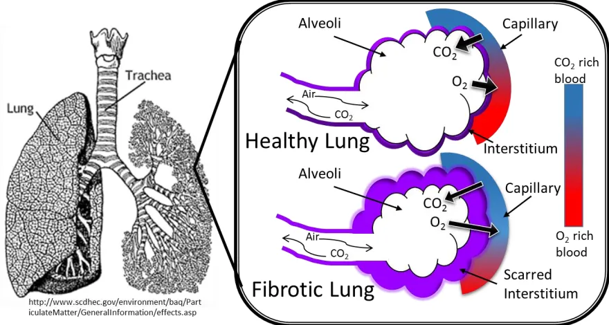
Figure 1.4. The secretion of extracellular matrix proteins by fibroblast cells is a necessary part of wound healing. Once the wound is healed, fibroblasts go through apoptosis to prevent overproduction of proteins. In pulmonary fibrosis, fibroblasts continue to survive and create proteins, leading to lung thickening. Thickening of the interstitial space of the alveoli leads to poor oxygen–CO2 transfer between the lungs and blood stream.
1.4.1 Pulmonary fibrosis and inflammation
Pulmonary fibrosis is a chronic disease of the lungs caused by excess accumulation of extracellular matrix (ECM) proteins and altering of the lung architecture. The death of epithelial cells coupled with altered fibroblasts leads to imbalanced proliferation and apoptosis of fibroblasts as well as ECM creation and breakdown.61 Idiopathic pulmonary fibrosis is the
most severe form with a mean survival of 3 years with no treatment options61
Chronic inflammation is often associated with fibrosis. Inflammation is a response to injury, infection or toxic exposure. The goal of inflammation is to recover normal tissue function but unresolved it leads to tissue damage. Inflammation works to remove invaders from the body and restore normal function to the affected area.62 An increase in macrophages, neutrophils and eosinophils along with an increase in pro-inflammatory cytokines are often observed in inflammation.
Macrophages are one of the first lines of defense against foreign particles in the body and work to phagocytose invaders. When the foreign object is too large this can lead to frustrated phagocytosis or the fusion of multiple macrophages to form huge cells able to engulf the invader62 which in turn leads to the release of reactive oxygen species (ROS) and hydrolytic enzymes.60 ROS are often a component of inflammation. ROS lead to damage to DNA, proteins, cell membranes, and mitochondria.61 Oxidative stress can originate from environmental toxins, mitochondria or the depletion of antioxidants among other things.63 Neutrophil influx is also characteristic of inflammation.64 Neutrophils are short lived granular leukocytes that also perform phagocytosis and can break down materials with enzymes, like myeloperoxidase, and have been known to degrade CNT.62 Eosinophils are less common white blood cells that are recruited to parasites, allergy and chronic inflammation; eosinophil peroxidase has been shown to degrade SWCNT.62
1.4.2 Nanoparticle-lung interaction following inhalation
When nanoparticles (NP) are inhaled, the upper airway is cleared by the mucociliary escalator while the lower airway is cleared by macrophage phagocytosis of particles smaller than 10 m followed by transportation to the mucociliary escalator or across the epithelium to the lymph. Neutrophils are also recruited to help clear nanomaterial. Macrophages are most able to clean materials that are close to their size (14-21 μm) with small (<100-200 nm) particles evading uptake.64,65 Following phagocytosis, phagosomes and lysosomes can combine to form
likely to interact with the epithelial cell lining and lead to fibrosis. Increased residence times of materials leads to increased negative health effects.64,65
Physical characteristics (size, shape, density) of NP can change where they deposit in the lungs with clearance and translocation dependent on geometry and surface area.64 Particles smaller
than 10 m can deposit in the alveoli while larger particles collect at larger branches. Increasing NP concentration can increase their aggregation and lead to increased clearance.65
NP are likely to deposit in alveoli if smaller than 100 nm or between 100 nm and 1 μm and of high density. NP inhalation will exhibit impaired clearance if the NP are smaller than 100 nm, fiber shaped, surface charged, and/or have slow to no dissolution. Increased inflammation is observed if NP have a high surface reactivity, fast dissolution or are cationic.64
1.4.3 MWCNT uses and current research
MWCNT are used in many different areas including: electronics, energy storage, sensors,3,60 organic light emitting diodes, transparent conductive coatings, capacitors, filtration,6 high strength materials, electronics,66 contrast imaging agent, drug delivery67 and flame retardants. Lung exposure to CNT has led to fibrosis in vivo using both mice and rats. Dong et al. exposed C57BL6 mice to 5-40 g of MWCNT via pharyngeal aspiration and observed the initiation of fibrosis after only one day as characterized by increased collagen in the lungs. The severity of fibrosis peaked after seven days and was maintained to their latest time point of 14 days. They also observed acute inflammation with increased macrophages and neutrophils. MWCNT were primarily deposited in the terminal and respiratory bronchioles as well as the alveolar ducts.68 CNT aggregate due to van der Waals forces. To disperse CNT they can be functionalized or ultra-sonicated. Ultra-sonication can break CNT into smaller pieces.69 Overcoming the van der
Long ridged MWCNT can lead to frustrated phagocytosis in macrophages which in turn leads to the release of ROS and hydrolytic enzymes.60 Some researchers believe that decreasing the length of a CNT will decrease toxicity because their smaller size would make them easier to clear. On the other hand, Mutlu et al. saw that long, dispersed CNT were clearable from the lung despite their aspect ratio. They hypothesize that aggregation of the CNTs causes toxicity and not the aspect ratio.71
Muller et al. also focused on the effect of dispersion and length by using long and short MWCNT. MWCNT were shortened via grinding and then used to expose Sprague-Dawley rats intratracheally (0.5-5 mg) and found better lung dispersion with shorter tubes. Unground tubes were poorly dispersed, had increased bio-persistence and caused collagen-rich granulomas in the bronchi. Ground tubes were better dispersed and led to granulomas in the alveolar space or interstitium with slightly decreased bio-persistence and increased inflammation attributed to better dispersion.66
In yet another study, the aggregate state was found to affect the biological response to CNT lung exposure. The extent and location of inflammation was dependent on the dispersal and aggregation of SWCNT with agglomerated tubes leading to granulomatous inflammation and fibrosis in the larger airways and dispersed SWCNT deposited in the alveoli and interstitium leading to peri-alveolar fibrosis.60
Another study determined that dispersal state was an important characteristic in determining inflammation. Additionally, they found surface functionalization to be a key parameter as it can change the CNT length, aggregation and degradation. They also found that increased length and width of CNT increased inflammation.62
1.4.4 ZnO uses and current research
ZnO is a wide band gap semiconductor72 with transparent, conductive, piezoelectric and UV
absorbant73 properties. ZnO has a bandgap of 3.37 eV with a high excitation binding energy of
ZnO finds uses in cell imaging, bio-sensing, drug delivery, targeted cancer treatment,72 solar cells, sensors, transducers, photo catalyst, foods, pigments, cement, paint, cosmetics, sunscreen73, antibacterial ointments, lotion, mouthwash,75 UV light emitting diodes, laser diodes, lasing media, optoelectronic devices in general,74 and piezoelectric generators when coated on CNT.76 It is also used as a dietary supplement because it stimulates the immune
system and acts as an anti-inflammatory at the right concentration.75 As an antibacterial it is more effective against gram-positive bacteria than gram-negative.73
In vivo zinc ions are coenzymes for many enzymes and are in zinc fingers found in transcription factors.77 Zinc is an essential trace element, one of the most abundant in cells. It is involved in cell structures, stabilization of cell membranes and catalytic functions. Without ZnO there is impaired immune function.78 But it is only good in moderation as excessive inhalation can lead to metal fume fever which has flu like symptoms.65
As ZnO is photocatalytic and can be used to degrade toxic components of industrial effluents, ZnO is currently being studied as a filter supported on MWCNT.79 Taking advantage of ZnO’s piezoelectric properties, a MWCNT coated with ZnO could be used as a nanoscale battery charger or sensor when a mechanical stress is applied. For instance, a car moving across a bridge would cause the bridge to vibrate, these vibrations could be transformed into electricity. Coating MWCNT with ZnO is being studied as a nanogenerator.76 MWCNT coated with ZnO have been shown to make a stable, but reversible, super-hydrophobic material using a surface of aligned MWCNT.80 With such a broad range of applications there is a substantial potential for human contact and inhalation.58 MWCNT can affect the health of workers, consumers, and the environment.56
ZnO is partially water soluble and the ions contribute to toxicity.73 For ZnO dissolution pH is
a major factor. ZnO can react with water to form OH-.73 Research has found that dissolution is
time and concentration dependent; ZnO is not highly soluble without low pH or chelators.75,81
Many people believe that the toxicity of ZnO is at least partially tied to Zn2+ release but the extent of which is unknown.73 Some people believe that ZnO toxicity is dependent on ROS formation, enzyme activity inhibition, and lysosomal/mitochondrial damage from altered Zn2+ homeostasis.73
Cho et al. studied the contribution of Zn2+ by exposing rats intratracheally to ZnO NP at 50 and 150 cm2/rat or Zn2+ ions at 92.5 and 277.5 g/rat and looked at the response after 24 hours, one week and four weeks. They found the responses to be similar between the two with increases in eosinophilia, proliferation of epithelial cells, goblet cell hyperplasia and pulmonary fibrosis. They believe the similarity stems from the fact that the ZnO NP are being engulfed by macrophages and dissolved in lysosomes, thus allowing the NP to quickly change to ions. One difference they did observe was that the high dose of Zn2+ led to rat death were the high dose of ZnO NP did not.75
Many others have concluded that Zn2+ plays a role but saw differences between ions and NP.75,82 For example, another group exposed A549 lung epithelial cells in vitro as well as rats in vivo to ZnO NP and Zn2+ to look at the contribution of Zn ions to inflammation. To create the ionic conditions, media was incubated with ZnO NP and then filtered to remove the NP. In vitro they found that both were cytotoxic but the ions alone were less cytotoxic and produced a smaller increase in IL-8. In rats, exposure to ZnO NP increased bronchoalveolar lavage fluid (BALF) levels of neutrophils and eosinophils; LDH and total protein after 24 hours were observed; and levels of increased total cells and eosinophils persisted to 28 days. Ions alone showed an increase in neutrophils at 24 hours with everything back to baseline by 48 hours.83 This led them to believe that the response seen was not from ions alone.
media alone (without cells) and cassette case. Moos et al. cited cellular factors as likely assisting in the dissolution of ZnO and these factors could not fit through the 10kDa cassette. The also observed higher apoptosis and decreased mitochondrial function for the smaller particles dosed on a mass basis.81
Buerki-Thurnherr et al. exposed Jurkat cells to ZnO NP and believe that cytotoxicity was not caused by ROS but from ZnO dissolution in the media. They found that N-acetyl cysteine (NAC) was the only antioxidant of four tested found to decrease cytotoxicity. NAC is a known chelator of Zn2+ so it was likely acting by sequestering ions and not as an antioxidant, thus pointing to ions and not ROS being the key factor in cytotoxicity. To look into dissolution, ZnO NP were coated to reduce the dissolution rate and this led to decreased cell death. The authors decided that dissolution occurred in the media as they could not visualize any NP in the cells via transmission electron microscopy. They concluded that ZnO NP toxicity was from ZnO dissolution extracellularly followed by cellular uptake of ions and ROS independent apoptosis.84
Xia et al. looked into the contribution of ROS and Zn2+ to the toxicity of ZnO NP to RAW 264.7 macrophages and BEAS-2B epithelial cells. ZnO NP led to increased toxicity, ROS, oxidant injury, inflammation, and cell death in both cell lines. ZnO was found in caveolae in epithelial cells and in lysosomes in macrophage cells. They found that Zn2+ from ZnSO4 were
1.4.5 AZO uses and current research
Alumina (Al) doping increases the conductivity of ZnO by making electrons more easily excited into the conduction band72 with the highest conductivity resulting from 3-7% Al.87 Alumina doped ZnO (AZO) is the best candidate to replace indium tin oxide (ITO) as the premier transparent conductive oxide (TCO).88 TCOs are necessary for transparent devices such as solar cells, flat panel displays and light emitting diodes. Currently ITO is the most commonly used TCO because it has a low resistivity and high transmittance, but indium is rare and toxic and ITO is generally unstable. AZO is a promising substitute with high transmittance and low resistivity with the added bonus that Al is abundant and nontoxic.89 AZO is more stable, cheap and environmentally friendly replacement for ITO.87
AZO has decreased solubility and crystallinity as compared to pure ZnO. After 24 hours of incubation in cell media the concentration of Zn2+ in cell media for AZO NP was half that of ZnO NP in one study72 with others also observing a decrease in Zn2+ in solution with Al doping.90 Al doping of ZnO alters the crystallinity of ZnO;91 with a high enough concentration of alumina films become amorphous and with just a small amount films exhibit decreased surface roughness and crystallinity.87
Less research has been done to explore the toxicity of AZO NP. The few studies that have been done contradict one another with some claiming AZO NP to be less toxic than ZnO NP and vice versa.
Xu et al. tested a group of NP made up of insulators and semiconductors including ZnO and AZO (3.4% Al) NP. They found that NP treated media had no effect on NIH3T3 mouse fibroblast cells or A549 human lung epithelial cells. This ruled out ions as major contributors to the cellular response and thus changes in solubility upon doping were not considered important. They found that the AZO NP were more toxic than the ZnO NP.92
to be a contributing factor to the cellular response because the antioxidant NAC increased cell viability. Unfortunately, NAC’s ability to chelate Zn2+ means the contribution of ions verses
ROS remains poorly understood.84 They hypothesize that the creation of ROS through a mitochondrial pathway is the main mechanism of MCF-7 toxicity.72 They went on to find that IMR-90 human lung fibroblasts and primary rat hepatocytes were not affected by treatment with either NP.
Pan et al. showed that AZO (purchased, 2% Al) was less cytotoxic than ZnO NP and saw a good correlation between zeta potential and viability.90 This contradicts the first study showing that AZO was more toxic than ZnO.
1.4.6 Brief summary of results
Previously Taylor et al. found that coating MWCNT with alumina via ALD decreased the fibrotic response in mice exposed via oropharyngeal aspiration.93 We sought to determine if other ALD coatings would also change the fibrotic response in mice in vivo or in cell culture in vitro.
The first coating tested was ZnO. In vitro we studied the cellular response using human monocytes (THP-1 cells). THP-1 cells are often used to model the innate immune system and the human inflammatory response.94 It was found previously that particle number is the best dosing strategy for nanomaterials.95 As such, cells were dosed by normalizing to the nanoparticle number as the coating significantly increases the weight of the MWCNT.
This inflammatory response in vitro matched our results in vivo. After exposing C57BL6 mice to MWCNT and Z-MWCNT via oropharyngeal aspiration, an acute inflammatory response was observed in mice exposed to Z-MWCNT and to a lesser extent MWCNT. There was an increase in total cells in the BALF and neutrophils observed from both nanomaterials with a significant increase in macrophages and neutrophils from Z-MWCNT. This was coupled with a significant increase in IL-6 and CXCL10 mRNA and protein in Z-MWCNT exposed mice. Systemic increases in IL-6 were also observed in Z-MWCNT treated mice with significant increases in the heart and liver.
Although the initial inflammatory response was more severe with Z-MWCNT treatment, by day 28 both showed similar cell profiles in the BALF and baseline cytokine levels. Levels of fibrosis were similar between the two treatments with the main difference being the location of fibrosis. Treatment with MWCNT caused more focal, condensed lesions at alveolar duct bifurcations whereas Z-MWCNT caused a more diffuse inflammatory response in the lower lung around terminal bronchioles, alveolar duct bifurcations and alveolar ducts. This initial inflammatory response is likely due to the presence of ZnO, which has been known to cause inflammation, and the change in physical properties of the MWCNT upon coating. Coated tubes are smaller, better dispersed and denser. All of these factors could lead to better dispersion in distal regions of the lung. The longer, more aggregated MWCNT deposit higher in the airway.
To mitigate the aggressive inflammatory response to Z-MWCNT we sought to alter the ALD coating. Mixed results had been seen previously with alumina doping of ZnO to create AZO NP. As we previously observed ALD alumina coatings to decrease the level of fibrosis as compared to uncoated MWCNT, we thought that doping would be an interesting place to start. We used AZO coatings to test the contribution of Zn2+ to toxicity as AZO is less soluble than
ZnO. To study the ion release we incubated A-, Z- and AZO-MWCNT in media alone or with various cell lines. Zn2+ concentration was partially dependent on the cell line, pH of the media
Z-MWCNT treatment. When differences in Zn2+ concentration were observed between Z- and AZO-MWCNT treatments there were also differences in the release of the pro-inflammatory cytokine IL-1. Together, these results mean that Zn2+ contributes to toxicity and inflammation
CHAPTER 2.Temperature-Dependent Reaction Between Trimethylaluminum and Poly(methyl methacrylate) during Sequential Vapor Infiltration: Experimental and Ab
Initio Analysis
The following work is reproduced with permission from Erinn C. Dandley, Craig D. Needham, Phillip S. Williams, Alexandra H. Brozena, Cristopher J. Oldham, and Gregory N. Parsons, “Temperature-dependent reaction between trimethylaluminum and poly(methyl methacrylate) during sequential vapor infiltration: experimental and ab initio analysis,” Journal of Materials Chemistry C, 44 (2014) 9416-9424.96 © 2014 Royal Society of Chemistry.
2.1 Introduction
Several active research groups currently explore polymer modification by vapor-phase, metal-organic reagents to understand reactions that alter material surface and bulk structure as well as functionality.97–104 Improved understanding of vapor infusion and reaction mechanisms will help expand the use of current methods, and will lead to the discovery of novel approaches or process schemes to enable new and broader applications. For example, sequential vapor infiltration (SVI) proceeds by repeatedly exposing a polymer, or other material, to a vapor reactant, usually a metal-organic species, in a heated reactor environment. After the reagent vapor flows into the reactor the deposition chamber is closed for a set “hold” time, increasing the net reactant exposure. Sequential exposures are separated by an inert gas purge to remove vapor byproducts and renew the reactant concentration. Co-reactants, such as water to produce metal oxide products, are also delivered either as an additional step within the reactant/inert gas sequence, or after completing the desired number of reactant infusion/purge cycles. This approach has grown from atomic layer deposition (ALD), which uses sequential, self-limiting reactant exposure steps to deposit conformal and uniform thin films on surfaces with monolayer precision33,105,106 Variations on the process take different names, including multiple
pulse infiltration 97,98 and sequential infiltration synthesis.101,102 Multiple pulse infiltration also