A Novel Center-Fed SIW Inclined Slot Antenna for Active
Phased Array
Yao Zong1, 2, Jun Ding1, *, Chenjiang Guo1, and Chao Li3
Abstract—In this paper, a center-fed substrate integrated waveguide (SIW) inclined slot array antenna is designed for a one-dimensional active phased array. A novel coaxial-to-SIW transition is employed to realize the central feed for enhancing bandwidth. The antenna prototype printed onto a single-layer Rogers 5870 is composed of 32×16 inclined slots working at Ku-band. As shown in measured result, the bandwidth with return loss < −10 dB is from 16.6 to 17.1 GHz, and the sidelobe levels of arrays are below −24.8 dB at 16.8 GHz in H planes. The measured gain is 31.8 dB at 16.8 GHz with the aperture efficiency of 65%. The active phased array is assembled by an antenna and 32 Tx/Rx modules, and the measured results show that the main lobe can obtain a wide-angle scanning from −45 to 45 degrees inE planes. The antenna array is suitable for low profile small active phased array radars and communication systems that require spatial wide-angle scanning.
1. INTRODUCTION
Substrate integrated waveguide (SIW) technology is a new type of waveguide structure that can be integrated into a dielectric substrate. In recent years, the development of materials science has also brought novel features to SIW technology [1–8]. Several high performance transitions have been designed for integrating SIW with different planar transmission lines, such as microstrip-to-SIW transition [9–12] and coplanar-to-SIW transition [13]. A structure of coaxial line to SIW transition is depicted in [14], which is located at one end of the SIW. The wideband SIW-to-rectangular waveguide (RWG) transition is proposed to ensure the performance of insertion loss in [15, 16]. Antennas based on SIW have the same excellent characteristics as a metal waveguide antenna, while being more compact, light weight, and easy to process. Some single-layer side-fed SIW longitudinal slot array antennas have been proposed in [17–20], but the bandwidth becomes inherently narrower as the antenna gain increases due to the long-line effect [21]. The partially corporate feed, especial centre feed, is a well-known technique for bandwidth enhancement of series fed arrays. A compact two-layer longitudinal slotted array antenna fed by an inclined slot at the center of the bottom metal layer of the SIWs is proposed in [22], and the relative working bandwidth is 80% wider than the same size end-fed array. A center-fed single-layer SIW longitudinal slots array antenna is designed with a coplanar-SIW transition [23], but the spacing between the slots on both sides of the feed position is almost twice as the spacing of others, resulting in the degrading of the sidelobe level (SLL). A center-fed SIW longitudinal slot linear array with a coaxial-to-SIW transition is proposed in [24], but the coaxial-to-SIW transition can only achieve good impedance matching with a specific width of SIW. Recently, SIW antennas have also been increasingly used in active phased arrays for radar and communication systems. A planar SIW slot antenna is proposed for active phased arrays with a wide-angle scanning from−71 to 73 degrees [25], which is fed by a microstrip-to-SIW transition at one side of SIW, and the SLL can only be below −10 dB.
Received 8 September 2019, Accepted 23 November 2019, Scheduled 17 December 2019
* Corresponding author: Jun Ding ([email protected]).
1 School of Electronics and Information, Northwestern Polytechnical University, Xi’an, People’s Republic of China. 2Xi’an Electronic
In this paper, a center-fed SIW inclined slot array antenna is proposed to realize an active phased array operating in the Ku band. A novel coaxial-to-SIW transition is designed to form the center feed for the inclined slots linear array to enhance the working bandwidth. The equivalent circuit model and parameter extraction model of the SIW inclined slots are established. The parameters of the two slots in the middle of the linear array are adjusted to eliminate the effects of the transition to obtain low SLL of the H-plane. 32 linear arrays are fabricated on a single-layer printed circuit board (PCB) and installed with 32 Tx/Rx modules for active phased array, which can obtain a wide-angle scanning in theE plane. Finally, the simulated and measured results of the fabricated antenna array are discussed to confirm its design validity.
2. DESIGN OF ANTENNA
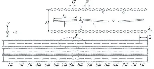
A top view of the SIW slot array antenna is shown in Fig. 1. The antenna consists of 32 linear arrays operating at 16.8 GHz, and only three linear arrays are shown here. The linear array is realized by 16 alternating inclined slots etched on the top metal layer in thexdirection. 8 slots in the left and right of a line array are mirror-symmetrical on both sides of the center of SIWs. The adjacent two linear arrays are designed to be mirror symmetrical in the y-direction in order to eliminate the polarization. The antenna is fabricated on a PCB of Rogers 5870 with relative permittivity 2.33 and thickness 0.508 mm. Two rows of metalized vias are fabricated on two long edges of the top metal layer. The propagation constant and radiation loss are determined by parametersa, w, anddwhich denote the width of the SIW, period, and diameter of vias, respectively. According to the experimental formula for the normalized width of the equivalent waveguide [8], parameters of the SIW are chosen as a= 7.6 mm, d= 0.8 mm, and w = 1.2 mm, respectively. On the top metal layer, slots with dimensions of resonant length L, inclined angle θ, and width of 0.5 mm are equally spaced on the center line of the SIW.
Figure 1. Configuration of the proposed 3×16 array antenna.
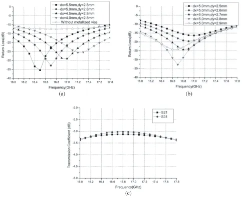
S31 are −3.05 dB and −3.15 dB, respectively. By comparison, the simulation results of insertion loss
are superior to the reported microstrip-to-SIW and coplanar-to-SIW transitions due to the absence of surface wave loss.
(a) (b)
Figure 2. Structure of the coaxial-to-SIW transition. (a) Top view of the structure. (b) Side view of the structure.
(a) (b)
(c)
(a) (b)
Figure 4. Extraction parameter of series inclined slots. (a) Extraction parameter model. (b) Equivalent circuit model.
An inclined slot etched on the center line of SIW can be equivalent to the normalized series impedance z = r +jb, and the imaginary part b = 0 represents the slot resonance. As shown in Fig. 4, the extraction parameter model and its equivalent circuit are established. Three slots in the model have the same length L and inclined angle θ, and each normalized series impedance can be approximated the same. The commercial simulation software ANSIS HFSS can conveniently be used for extracting the slot parameters, and the mutual coupling caused by adjacent slots has been taken into account in the calculation results. By estimation, the maximum normalized resistance value required in the design is less than 1/3. According to the microwave circuit scattering matrix theory, when the slots approximate resonance (b≈0), the normalized impedance is given by:
r= 1− |S11| 3(1 +|S11|)
(r≤1/3) (1)
where S11 is the reflection coefficient of port1, and r is the normalized impedance (the average of
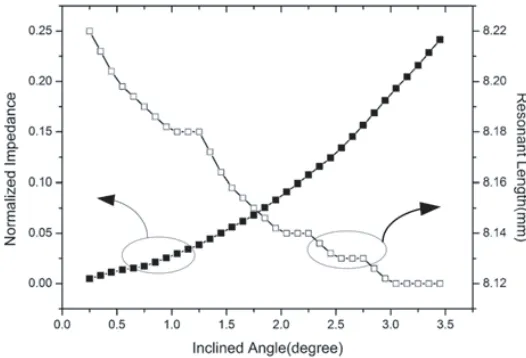
the three slots). The extracted parameter curves about r (represents the normalized impedance) and L (represents the resonant length) against the inclined angle θ are shown in Fig. 5. The required normalized impedance values for each radiating slot in the linear array are obtained depending on the
−28 dB Taylor distribution, and the inclined angle and resonant length of the radiating slots can be obtained from the curve of Fig. 5. By the optimization of numerical calculation and simulation, the geometric parameters of the 16 inclined slots in the linear array are listed in Table 1. The parameters of the two slots in the middle have to be modeled separately to obtain the parametric curve because the two matching metallized vias affect the electric field distribution of the SIW. As can be seen from Table 1, the two slots on both sides of the feed point are longer than normal.
Table 1. Dimensions of eight slots.
Number L (mm) θ (degree)
1# 8.18 1.0
2# 8.18 1.2
3# 8.16 1.6
4# 8.14 1.9
5# 8.13 2.7
6# 8.12 3.1
7# 8.12 3.2
8# 8.65 4.8
3. EXPERIMENTAL RESULTS AND DISCUSSION
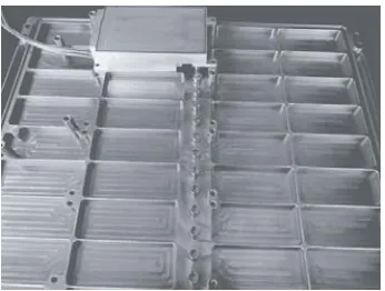
To verify the proposed design, a 32×16 SIW inclined slot array antenna with the aperture size of 330 mm×180 mm is fabricated and shown in Fig. 6. As shown in Fig. 7, the Tx/Rx module is mounted
(a) (b)
Figure 6. Photograph of the proposed array antenna. (a) Top view. (b) Bottom view.
Figure 7. Photograph of the antenna with Tx/Rx module installed.
on the bottom of the antenna and connected to the coaxial connector of the transition.
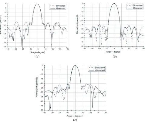
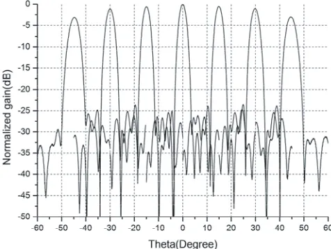
The simulated and measured return losses of the proposed linear array are shown in Fig. 8. The measured −10 dB return loss bandwidth of the linear antenna array is 0.5 GHz, ranging from 16.6 to 17.1 GHz, which is shifted to a lower frequency by 50 MHz due to manufacturing errors and assembly errors compared to the simulation results. The radiation patterns of H-plane are simulated and measured, which are shown in Fig. 9 at frequencies of 16.6, 16.8, and 17.0 GHz. As can be seen, the measured radiation patterns have good agreements with the simulation results, and the measured SLL at 16.8 GHz is lower than −24.8 dB. All other frequency results are below −20 dB. The measured gain at 16.8 GHz is 31.8 dB with the aperture efficiency of 65%. In the operating band, the frequency of 16.8 GHz is selected to show the scanning pattern in theE-plane. By controlling the 5 bit digital phase shifter in the Tx/Rx modules, the beam scanning patterns of 0◦, ±15◦,±30◦, and±45◦ are measured respectively, which are shown in Fig. 10. It can be seen that the gain is only decreased by 2.7 dB when scanning from 0 to 45 degrees, and the SLLs of all the scanning patterns are below−20 dB. In summary, the designed antenna array is suitable for active phased arrays with wide angle scanning.
(a) (b)
(c)
Figure 10. Measured scanning pattern in theE-plane at 16.8 GHz.
4. CONCLUSIONS
A center-fed SIW inclined slot linear array has been proposed, fabricated, and tested. A novel coaxial-to-SIW transition suitable for center feed has been developed with good impedance matching and insertion loss. The array antenna achieved −10 dB return loss bandwidth and SLL < −20 dB from 16.6 GHz to 17.1 GHz, demonstrating that the bandwidth is effectively enhanced relative to the side fed SIW antenna. The SIW inclined slots radiating element has also been proven to have good wide-angle scanning characteristics through active phased array beam scanning testing. The structure is small, low in cost, and easy to integrate, and also provides a design method for realizing a highly integrated one-dimensional active phased antenna.
REFERENCES
1. Prakash, S., S. Dash, and A. Patnaik, “Reconfigurable circular patch THz antenna using graphene stack based SIW technique,”2018 IEEE Indian Conference on Antennas and Propogation (InCAP), Hyderabad, India, 2018.
2. Zhang, A. Q., Z. G. Liu, and W. B. Lu, “A tunable attenuator on graphene-based half-mode substrate integrated waveguide,”2018 IEEE Asia-Pacific Conference on Antennas and Propagation (APCAP), 4, Auckland, New Zealand, 2018.
3. Giordano, M. C., S. Mastel, and C. Liewald, “Phase-resolved terahertz self-detection near-field microscopy,” Opt. Express, Vol. 26, 18423, 2018.
4. Mitrofanov, O., L. Viti, and E. Dardanis, “Near-field terahertz probes with room-temperature nanodetectors for subwavelength resolution imaging,” Sci. Rep., Vol. 7, 44240, 2017.
5. Viti, L., J. Hu, and D. Coquillat, “Efficient terahertz detection in black-phosphorus nano-transistors with selective and controllable plasma-wave, bolometric and thermoelectric response,” Sci. Rep., Vol. 6, 20474, 2016.
6. Boukhvalov, D., B. G¨urbulak, and S. Duman, “The advent of indium selenide: Synthesis, electronic properties, ambient stability and applications,”Nanomaterials, Vol. 7, 372, 2017.
7. Liu, C., L. Wang, and X. Chen, “Room-temperature high-gain long-wavelength photodetector via optical-electrical controlling of hot carriers in graphene,”Adv. Opt. Mater., Vol. 6, 1800836, 2018. 8. Tang, W., A. Politano, and C. Guo, “Ultra sensitive room-temperature terahertz direct detection
based on a bismuth selenide topological insulator,”Adv. Funct. Mater., Vol. 28, 1801786, 2018. 9. Farrall, A. and P. Young, “Integrated waveguide slot antennas,” IEEE Electron. Lett., Vol. 407,
10. Bozzi, M., A. Georgiadis, and K. Wu, “Review of substrate-integrated waveguide circuits and antennas,”IET Microwaves, Antennas Propagation, Vol. 5, No. 8, 909–920, 2011.
11. Djerafi, T. and K. Wu, “Corrugated substrate integrated waveguide (SIW) antipodal linearly tapered slot antenna array fed by quasi-triangular power divider,” Progress In Electromagnetics Research C, Vol. 26, 139–151, 2012.
12. Zou, X., C.-M. Tong, and D.-W. Yu, “Y-junction power divider based on substrate integrated waveguide,” IEEE Electron. Lett., Vol. 47, No. 25, 1375–1376, 2011.
13. Taringou, F., J. Bornemann, and K. Wu, “Broadband coplanar waveguide and microstrip low-noise amplifier integrations for K-band SIW applications on low-permittivity substrate,” IEEE Trans. Antennas Propag., Vol. 8, 99–103, 2014.
14. Khan, A. A. and M. K. Mandal, “A compact broadband direct coaxial line to SIW transition,”
IEEE Microwave Wireless Compon. Lett., Vol. 26, 894–896, 2016.
15. Park, S.-J., D.-H. Shin, and S.-O. Park, “Low side-lobe substrate-integrated-waveguide antenna array using broadband unequal feeding network for millimeter-wave handset device,” IEEE Antennas Wirel. Propag. Lett., Vol. 64, 923–931, 2016.
16. Xia, L., R. Xu, and B. Yan, “Broadband transition between air-filled waveguide and substrate integrated waveguide,” Electron. Lett., Vol. 42, 1403–1405, 2006.
17. Yang, D., F. F. Gao, and J. Pan, “A single-layer dual-frequency shared-aperture SIW slot antenna array with a small frequency ratio,”IEEE Antennas Wirel. Propag. Lett., Vol. 17, 1049–1051, 2018. 18. Li, Y., W. Hong, G. Hua, J.-X Chen, and K. Wu, “Simulation and experiment on SIW slot array
antennas,”IEEE Microwave Wireless Compon. Lett., Vol. 14, 446–448, 2004.
19. Liu, B., et al., “Substrate integrated waveguide (SIW) monopulse slot antenna array,”IEEE Trans. Antennas Propag., Vol. 57, No. 1, 275–279, 2009.
20. Kim, D.-Y. and S. Nam, “Excitation control method for a low sidelobe SIW series slot array antenna with 45 linear polarization,” IEEE Trans. Antennas Propag., Vol. 61, No. 11, 5807–5812, 2013.
21. Ando, M., Y. Tsunemitsu, and M. Zhang, “Reduction of long line effects in single-layer slotted waveguide arrays with an embedded partially corporate feed,” IEEE Antennas Wirel. Propag. Lett., Vol. 58, 2275–2280, 2010.
22. Li, T. and W.-B. Dou, “Millimetre-wave slotted array antenna based on double-layer substrate integrated,” IEEE Trans. Antennas Propag., Vol. 9, 882–888, 2015.
23. Xu, J.-F., Z.-N. Chen, and X.-M. Qing, “CPW center-fed single-layer SIW slot antenna array for automotive radars,”IEEE Antennas Wirel. Propag. Lett., Vol. 62, 4528–4535, 2014.
24. Chen, M. and W.-Q. Che, “Bandwidth enhancement of substrate integrated waveguide (SIW) slot antenna with center-fed techniques,” IEEE Antennas Technology (iWAT), 349–351, 2011.
25. Wen, Y.-Q. and B.-Z. Wang, “Wide-beam SIW-slot antenna for wide-angle scanning phased array,”