MOBILE ROBOT-BASED VIRTUAL V-BLAST MIMO
TRANSMISSION SCHEME IN DISTRIBUTED
WIRELESS SENSOR NETWORKS
1WENBAI CHEN
,
2WEI LI,
3XIAOPIN ZHANG1School of Automation, Beijing Information Science and Technology University, Beijing 100192, China
2
China electronics engineering design institute, Beijing 100840, China
3
State Key Laboratory of Information Photonics and Optical Communications, BUPT, Beijing 100876, China
ABSTRACT
Aiming at the requirements of high-speed data transmission and low energy consumption in energy constrained Wireless Sensor Networks (WSNs), a mobile robot-based virtual V-BLAST cooperative MIMO transmission scheme and an efficient approximate maximum likelihood (ML) detection algorithm are proposed in this paper. Mobility of robot can reduce the communication distance between the sensor nodes, MIMO-based WSNs can use its diversity gain to overcome fading effects and can also use its multiplexing gain to increase the data transmission rate. As for the detection algorithm in mobile robot-based virtual V-BLAST transmission scheme, combined with traditional decoding OSIC algorithm, the vectors needed to be detected in approximate ML algorithm are reduced. Mobile robot can receive with its own multi-antenna or using collaborative nodes around, and the energy efficiency analysis of the two cases are all discussed. Simulation results show that the proposed scheme effectively reduces network energy consumption, and the efficient approximate ML detection algorithm further improves energy-efficiency.
Keywords: Wireless Sensor Networks(WSNs), Mobile Robot(MR), Multiple-input multiple-output antenna
technology(MIMO), Vertical-bell layered space time Architecture (V-BLAST), Maximum Likelihood detection(MLD)
1. INTRODUCTION
In emergency of disasters, such as earthquake and fire, it is very significant to grasp the first-hand information on the scene of the accident to improve rescue efficiency, to minimize casualties and losses[1].Having the features of wide coverage, strong adaptability and flexible layout, Wireless Sensor Networks (WSNs) can quickly build the network of information gathering, monitoring and communications in the disaster-stricken area, and the robot can form a flexible, efficient and fast rescue system under the support of the sensor network. So, it puts forward higher requirements for WSNs to improve the transmission of data, voice and image[1-2].
Integrating the key technology of next generation mobile communication systems - Multiple-input Multiple-output (MIMO) technology[3] into WSN can make use of the diversity gain to overcome fading effects and make use of the multiplexing gain to improve the information transfer rate, thus to greatly improve energy-efficiency of the network[3-4].
As MIMO-based WSNs has become a new hotspot and mobile robot has the capabilities of being flexible and autonomous, introducing the robot technology into WSNs can easily change the topology of WSNs and improve the dynamic performance of the network[4]. By the powerful mobile performance of Mobile Robot (MR) and powerful communication performance of MIMO technology the energy efficiency of WSNs can be improved to enhance the overall performance of WSNs[5]. Apparently, upgrading WSNs performance will further enhance the sensory abilities of the mobile robot. The organic integration of WSNs, MR and MIMO will make a contribution to building a powerful autonomous system amidst communication, measurement, control and implementation.
2. V-BLAST SYSTEM
indicate that the V-BLAST detection has become a variety of research topics[6-8]. There are commonly-used detection algorithms like linear receiver algorithm, sorting interference cancellation algorithm, QR decomposition algorithm and MMSE algorithm.
11
h
21
h
R1 n
h
1
r
1
r
R n
r
1
x
2
x
T n
x R T n n
h
12
h
22
h
T 2n
h T 1n
h R2 n
[image:2.612.135.268.174.285.2]h
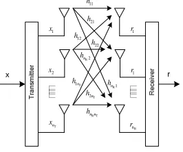
Figure 1: Transmission model of MIMO system
2.1 Point-Point MIMO Wireless Systems
Although encryption can provide multimedia content with the desired security during transmission, once a piece of digital content is decrypted, the dishonest customer can redistribute it arbitrarily[2, 3].
As shown in Figure 1, we consider a narrowband MIMO system channel model with M transmit and N receive antennas ( M ≤N ,also denoted as
M×N system). Under the assumption of ideal
timing and symbol-synchronous receiver sampling, the N dimension received signal vector
1 2 ( , ,...,r r rN) =
r can be modeled as
+
t t t
r = Hx n (1)
where 1 2 m T
t t t
x , x ,...x
=
t
x denotes the M
dimensional transmit signal vector, and satisfies
{
H}
m
E x xt t =PI ,where the superscript H stands for
the Hermitian transpose. The average transmission power of each transmission antenna is set equal to P. nt is N dimensional complex additive white Gaussian noise(AWGN)vector, of which each component is statistically independent, and has zero mean and a variance 2
/ 2
σ per dimension. It satisfies E
{ }
n nt tH =σn2In. Moreover, His a MIMOchannel matrix with the element
ofhji
(
1≤ ≤i M,1≤ ≤j N)
.Each element h refers ji to the fading between transmitter i and receiver j, which is modeled as independent complex Gaussian random variables of equal variance andsatisfies E h
{ }
ji2 =1.2.2 OSIC Decoding Algorithm of V-BALST
The traditional V-BALST decoding algorithm— OSIC can be described briefly as follows:
Initialization: i=1
1
G =H+ (2) Iterative process:
{1, 2 1}
( )
2
,
arg min
i
i j s s s i j
s G
−
∉ =
K
(3)
( )
i i
S i s
W = G (4)
T
i i
s S i
y =W r (5)
( )
ˆi i
s s
x =Q y (6)
( )
1 1 ˆi i
i s s
r+ = −r x H (7)
i
1
i s
G+ =H+ (8)
1
i = i+ (9)
Where , H
+ denotes Moore-Penrose
pseudo-inverse of matrix H, ( )Gi siis the
th i
s column vector of
i
G , Hsi
+
is pseudo-inverse of matrix Hsi which
obtained by eliminating the th i
s column of H . Function Q( )• denotes slicing operation of the
constellation. Equation(3) denotes the operation optimal ordering ,which is used to select the layer with biggest post-detection signal-to-noise ratio to detect. Equation (5) denotes the operation of nulling all but the th
i
s transmitted symbol and (7) denotes
the operation of interference cancellation.
V-BLAST first decodes the “strongest signal, then cancels the effect of this strongest transmission signal from each of the received signals, and then proceeds to decode the “strongest “of the remaining transmission signal, and so on.
3. MOBILE ROBOT-BASED VIRTUAL
V-BLAST MIMO TRANSMISSION SCHEME
3.1 Virtual MIMO Technique
Cooperative communication can be traced back to the research work about relay channel of Cover and EI Gamal [9] in the 1970s. User cooperative diversity concept was first introduced by A. Sendonaris et al in 1998 [10]. Almost at the same time, Laneman et al proposed various collaborative strategies of fixed relaying in Ref.[4], selective relaying based on channel measurement and enhanced relaying based on the feedback of terminal node. As a result, cooperative communication has also become a hot research topic in cellular network, Ad-hoc network and other communications [6-9].
mobile terminals to forward copies of signals, which constitutes a virtual multi-antenna system. Compared with multi-input and multi-output system with the traditional airspace, cooperative diversity allows multiple terminals with a single antenna to share each other's antenna in a multi-user environment to form a virtual multiple antennas structure which can obtain diversity gain.
STBC-based cooperative MIMO scheme improves the energy efficiency of the system by improving BER performance. While the scheme based on V-BLAST improves the energy efficiency by reducing the transmission time.
In STBC coded cooperative transmission scheme multi-node at the transmitter side makes full use of the multi-antenna transmission diversity and obtains coded cooperation diversity gain to overcome the channel fading actually. On the other hand, multiple sensor nodes simultaneously transmit their data to the receiving side in V-BLAST-based cooperative transmission scheme. Obviously, the scheme makes full use of the spatial multiplexing gain and improves transmission rate.
In general, STBC is more appropriate to low-rate, high-reliability and low transmission delay applications, while V-BLAST-based scheme is more appropriate to high-speed, low-reliability applications, such as audio/video information transmission.
V-BLAST-based cooperative MIMO
Transmission was proposed by Jayaweera [12]. At the transmitter side, The sensor nodes transmit their own perceived data to the receiver side independently and simultaneously. Therefore, this program is easier than STBC program mentioned above, because there are no joint encoding process at the transmitter side.
Launching their own perceived data independently and simultaneously to the receiver side means that the synchronization of data acquisition nodes is a necessary condition that should be considered in collaborative MIMO transmission which is based on V-BLAST. Of course, the synchronization will bring additional energy consumption, but this process can be completed by one leader node, which is not constrained in the energy consumption. Like other References, this paper assumes that data acquisition nodes have been synchronized, and this part of the energy consumption is ignored in the following discussion.
Transmitter Collective Nodes
Receiver Collaborative
Nodes
.
.
.
[image:3.612.326.515.556.636.2]Sink Node
Figure 2: V-BLAST Collaborative MIMO transmission scheme
The process of cooperative receiving of the V-BLAST encoding is shown in Figure 2. Sink node may require multiple secondary nodes around to be involved in receiving the signal to build the receiving end of multi-antenna structure. Aided receiving node can send the received signal to sink node in the next time slot. Sink node makes an appropriate choice of the decoding algorithm to obtain the signals transmitted by data acquisition nodes, according to the signal received from its own antenna and the auxiliary node. The results of Jayaweera S.K. show that the program can significantly improve energy efficiency in a multi-path fading environment, and the more the number of collaborative nodes has, the better energy efficiency can be obtained.
3.2 Discussions on MR-Based V-BLAST Transmission Scheme
Mobile robot can move at will, and its energy can be unrestricted compared with the common nodes of the sensor networks. So, using Mobile robot as a relay or a Sink node, can benefit data acquisition and prolong the lifetime of WSNs.
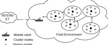
MR-Based V-BLAST transmission scheme is shown in figure 3. According to the space constraint in application, the robot can be mounted multi-antenna directly or use multiple secondary nodes around to build virtual multi-antenna .
Figure 3: MR-Based V-BLAST Transmission Scheme
decoding algorithm is inevitable, because of the poor calculating ability.
In some applications of WSN, the physical dimensions of the sink node can be unrestricted, so it is possible to install multiple antennas directly, which can further eliminate the need of local communication in receiving side. Generally, the energy consumption of sink node is not constrained, so the high BER performance of the receiver algorithms has great significance in practice.
3.2.1 MR serving as a sink node
Generally, all the nodes are deployed staticly in WSN. The nodes close to the sink node are easy to become the bottleneck of the network, because they transmit forwards all data from other nodes and the power consumption is very great.
According to the acquisition task and geographic regions, the sensors can be grouped. Being a mobile node, the mobile robot can determine the routes, the data acquisition place and the time to complete data acquisition, according to the mission of data acquisition and the maximization of network’s lifetime. Of course, the mobile robot also can do data acquisition when they move continuously on a optimal mobile path based on geographic traffic model.
The communication distance of the sensor nodes and the number of relay tasks is reduced in the scheme because of the movement of the mobile robot. It also makes the bottleneck nodes be distributed in the network evenly, which can prolong the network’s lifetime significantly.
The problem to be considered in the scheme is that the data store and data processing ability of the mobile robot. On some other real-time occasions, such as fire detection, mine rescue, the mobility of convergent node and the connectivity to the backbone network are all necessary. Moreover, in order to transfer the perception information, the location of the mobile robot is also necessary to all the sensor nodes.
3.2.2 MR serving as a relay node
With relatively rich resources, mobile robots serving as relay transmission tasks can let the normal nodes focus on data acquisition. There is no need to transfer data to the convergent nodes by multi-hop. Sensor nodes will directly transfer the data to a mobile relay node with one jump, and the mobile relay node will transmit the data to the convergent node. This program also can greatly improve the energy efficiency of the sensor networks, because the original long-distance
multi-hop communication becomes a short-range single-hop communication.
3.2.3 Detection algorithm of MR-based V-BLAST transmission
In terms of the performance, the maximum likelihood detector (MLD) is optimal in the sense of minimization of bit error rate, but it is not practical for its complexity. Its complexity increases exponentially with the number of transmission antennas and the modulation size. In terms of M transmission antennas and using CQAM as an example, ML detection can be expressed as:
^ 2
arg min j
m C j∈
= −
x
r Hx
x (10)
Where C is the number of constellation. ML algorithm is not practical, so it is necessary to study more efficient algorithms.
Since ML detection algorithm’s complexity comes from detecting every layer’s possible symbols in aggregate C , then the question is that m every element in Cm has the same probability? Obviously, it’s not every detection is useful. So, the basic method to reduce complexity of ML algorithm is to reduce the number of elements(symbols) in constellation which is used to decode[11].
So, we wish to find one transmitter antenna, W (W<C) points in the constellation as a subset to the
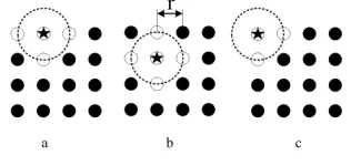
[image:4.612.339.497.560.635.2]ML detection. It means that C times detection is m decreased to W (W<C) times in the efficient ML detection algorithm. Firstly, we select a neighborhood of the best solution (the detected symbol of the optimal layer) of the OSIC algorithm as the candidate detection set. The candidate set of neighborhood is shown in Fig 1. Secondly, we use OSIC algorithm again to obtain other layers’ candidate symbols. The specific method is described particularly in Fig. 4.
Figure 4: Subset Of Constellation Point
As can be seen from Fig. 4, there are two factors that influence the number of constellation points around the best solution’s the neighborhood. One is the radius of the circle, and the other is the location of the best solution in the constellation diagram. Obviously, there are three constellation points around the best solution in Fig. 4(a), and four points in Fig. 4(b) , two points in Fig. 4(c).
The efficient Approximate Maximum Likelihood Detection procedure for MIMO communication systems is depicted in Fig. 5. In this Fig.,
1 2
,
,
,
Wk k k
x x
L
x
denotes the one-dimensional candidates of maximum likelihood detection, in which W is the number of constellation points in the neighborhood, k is the mark of the “strongest” layer of V-BLAST algorithm (normally last layer is the best, that is, k=m ).The detection algorithm in Fig. 5 can be further described as the following steps:
Step 1: Using the original V-BLAST algorithm
to get the signal of the “strongest”(optimal) layer.
Step 2: Choosing a neighborhood around the
symbol detected by OSIC of the optimal layer as the candidate set for the new algorithm.
Step 3: Choosing a possible symbol
i k
x from the
candidate set.
Step 4: Cancelling the effect of interference in
received vector r caused by
i k
x ,then get a new
vector r , this step can be expressed as: i 0, , 0, , 0
i i
k
x
= − L L
r r H (11)
Step 5: Eliminating the k-th column of channel
transfer matrix H, then get matrix HS.
Step 6: According to vector r and matrix i HS,
Use OSIC algorithm to detect these symbols :
( ) ( )
1 1, 1,
i i i i
m
k k
x%,Lx% − x% + Lx%
.
Step 7: From i=1 to W, repeating step 3 to step
6, we can get a group of symbols as follows:
( ) ( )
1 1 1 1
1 k 1, k 1, m
x%,Lx% − x% + Lx%
; ( ) ( )
2 2 2 2
1 k 1, k 1, m
x%,Lx% − x% + Lx%
;...
; ( ) ( )
W
1 1, 1,
W W W
m
k k
x% ,Lx% − x% + Lx%
.
Step 8: Using Maximum likelihood rule to
determine the output x in step 7. This detection rule can be denoted as:
( ) ( )
~ ~ ~ ~
1 1 1
1, 2 , , m
a rg m in , , , , , m
i i i i
i
k k k m
i
P
x x − x x + x
=
= −
x r H
L
[image:5.612.311.514.72.317.2]L L
Figure 5: The New Reduced Complexity ML Detection Algorithm Procedure
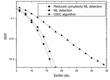
In order to compare, the performance of the traditional OSIC detection algorithm , ML detection algorithm and the proposed reduced complexity approximate ML detection algorithm in this paper are shown in Fig.6. Simulation is about 4*4 MIMO systems and 16QAM constellation.
Figure 6: Performance Comparison
[image:5.612.329.513.424.559.2]4. ENERGY EFFICIENCY ANALYSIS AND SIMULATION
Compared with the normal data gathering nodes in WSN, the mobile robot’s energy can be unrestricted, so this part is ignored in the following discussion. In this transmission program, Energy consumption is mainly concentrated on the remote communication from the data gathering node at the transmitter to the receiving nodes and the local communication from the collaborative nodes to the SINK node at the receiving side.
The communication distance in the wireless sensor network is generally a few hundred meters or less. Circuit power consumption can not be ignored, compared with transmission power. Sometimes circuit power may be greater than transmission power.
The total power consumption along a signal path can be divided into two main components: the power consumption of all the power amplifiers
PA
P and the power consumption of all other circuit
blocks PC. The total power consumption of the power amplifiers can be approximated as[12]
2
2 (4 )
(1 ) (1 )
k l f out
PA b b
t r
d M N
P P E R
G G
π
α α λ
= + = +
(12)
Where, Pout is the transmission power, 1 ε α η= − with η being the drain efficiency of the RF power
amplifier and
ε
being the peak-to-average ratio (PAR) that depends on the modulation scheme and the constellation size. For M-QAM systems,2 1
1
3M M
M
ε − +
−
= .
d is the transmission distance, k is the channel path loss exponent, Gt andGr are the transmitter and
receiver antenna gains respectively, Ml is the link
margin compensating the hardware process variations and other additive background noise or interference, Nf is the receiver noise figure, Eb is
the average energy per bit required for a given bit-error-rate (BER) specification and Rb is the system
bit rate.
Note that the receiver noise figure Nf is given by 0
/
r f
N =N N where Nr is the power spectral density (PSD) of the total effective noise at the receiver input and N0 is the single-sided thermal noise PSD at room temperature [12]. The signal attenuation parameter k could usually lie in the range 2-4 for wireless communications channels, with k=2 corresponding to free space propagation.
The total circuit power consumption PCcan be divided into Pct at the transmitter side and P at the cr
receiving side. we may estimate the power consumption as
( syn)
ct t DAC mix filt
P =M P +P +P +P (13)
( )
cr r LNA mix IFA filr ADC syn
P =M P +P +P +P +P +P (14)
Where, PDAC,Pmix,Pfilt,Psyn,PLNA,PIFA,PfilrandPADC are the power consumption values for the D/A converter (DAC), the mixer, the active filters at the transmitter side, the frequency synthesizer, the low noise amplifier (LNA), the intermediate frequency amplifier (IFA), the active filters at the receiver side and the A/D converter (ADC), respectively [1]. Assuming that there are Mt transmitter and the
symbol rate of the every transmitter is Rs, the
effective bit rate of the system can be given by
2
logM
t s
bt
R =M R (15)
According to (13) and (14), the total energy consumption per bit in a M-ary QAM MIMO system is 2 2 2 2 2 2 1 1 log (4 ) (4 ) 3 PA C bt k C bt k C M t bt l f b t r l f b
t r s
P P R P d R P M M d M E M N E G G M N E
G G M R
π λ π λ ε η η + = = + − + + − = (16)
As an example, considering the simulation conditions in Ref.[12], the main communication parameters are listed in Table 1.
Table 1: Communication Parameters
Parameters values Parameters values
PDAC 15.7 mW η 0.35
PADC 6.7 mW PLNA 20 mW
Pfilr 2.5 mW PIFA 3 mW
Pfilt 2.5 mW GtGr 5 dBi
fc 2.5 GHz N0 – 171 dBm/Hz
Pmix 30.3 mW Ml 40 dB
Psyn 50 mW Nf 10 dB
4.1 Mobile Robot Receiving With Its Own Multi-Antenna
In the first scheme, the mobile robot has its own multi-antenna. Assuming that, the modulation scheme is 16QAM constellation, Mt =Mr=4,. The system requirement of SER is 0.001, and the channel path loss factor is k=2.
networks can be approximated as the energy consumption of the long-haul communications at the transmitter side. So the average energy per bit for VMIMO communications system in the WSNs can be written as:
2 2 2 2 1 1 log (4 ) 3
mimo k ct
M t l f
b bt b
t r s
P M M
d M
M N
E E E
G G M R
π λ
η − +
= +
−
= (1
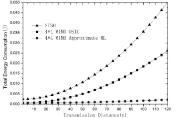
[image:7.612.106.283.280.399.2]7) Figure 7 shows the total energy consumption of the 16QAM constellation, 4×4 VMIMO communication transmission in sensor networks for different communication distances. At the transmitter side, there are four data gathering nodes sending total 1024 (4 * 256) bits. At the receiver side, the mobile robot has four receiving antennas.
Figure 7: Total Energy Consumption Of 4×4 MIMO Vs. SISO In The Scheme Of Mobile Robot Receiving With Its
Own Multi-Antenna
As an example for 100m transmission distance, the energy consumption is 0.0356 joules in SISO transmission scheme. While in the robot-based 4 × 4 VMIMO transmission scheme, the energy consumption is decreased to 0.0184 joules and 0.00173 joules, when OSIC algorithm and approximate ML algorithm are adopted respectively. They are above 51.6% and 4.8% relative to the SISO transmission scheme.
Obviously, the proposed scheme effectively reduces network energy consumption, and the low-complexity maximum likelihood detection algorithm further improves energy efficiency.
4.2 Collaborative Nodes Assisting Mobile Robot Multi-antenna Receiving
Assuming that there are Mt data gathering nodes
at transmitter side, and Lbits needs to be sent to the sink node for every gathering node. At the receiver side, the mobile robot serves as the SINK node and Mr−1 nodes around participate in
collaborative receiving for the mobile robot. After receiving signal sample from the transmitter side, collaborative nodes send the received signal to the mobile robot(sink node) in
the next time slot. The robot makes an appropriate choice of the V-BLAST decoding algorithm to obtain the signals transmitted by data acquisition nodes, according to the signal received from its own antenna and all the collaborative nodes.
The total energy consumption from the data gathering nodes to the robot can be calculated as
( ) ( )
2
1) log (
mimo L r ct l
t bt M bt
qLP M L
E = E + M − E (17)
Where, ( )L bt
E denotes the average energy consumption per bit in the long-haul transmission.
( )l
bt
E denotes the average energy consumption per bit in the local transmission. M denotes the QAM constellation size used for long-haul communications and thus / log2
M
L is the total number of signal samples received by the sensor nodes at the receiver side. q is bits number needed for the each received sample, from collaborative nodes to the robot.
Since during each time-slot, only one collaborative node is communicating with the robot at the receiver side. As long-haul communications, the total energy per bit for a fixed rate MQAM system can be estimated as
( ) ( ) ( ) 2 2 2 2 1 1 log (4 ) 3
l PA C k l C
l M
bt
l f
bt b
t r s
P P M M P
d
R M
M N
E E
G G R
π λ η + − + = + −
= (18)
Where circuit power consumption Pcduring local
communications can be written as
( ) ( )
c LNA mix IFA filr ADC syn DAC mix filt syn
P=P +P +P +P +P +P +P +P +P +P
(19)
Note that, the mobile robot has no energy constraints, Pc can be estimated by the second part
( )
c DAC mix filt syn
P= P +P +P +P .According to Ref. [12],
in case of an AWGN local channel, the average transmitting energy consumption per bit
E
b( )l can be described as( ) 0 1 2 2
2
( 1) log ( )
( )
3log ( ) 4(1 (1/ )
l b
N M BER M
Q
M M
E = − × −
−
(20)
In case of a Rayleigh fading local channel, the average transmitting energy consumption per bit
E
b( )l can be described as( ) 0 2 2 1
2
2 ( 1) log ( )
((1 ) 1)
3log ( ) 2(1 (1 / )) l
b
N M BER M
M M
E = − × − − − −
− (21)
Figure 8 shows the energy consumption when collaborative nodes assisting mobile robot multi-antenna receiving scheme is adopted.
From Figure 7 and Figure 8, we can see that the total energy consumption of this scheme is higher than that of mobile robot receiving with its own multi-antenna. That is because the discussion here is based on the assumption, the energy consumption of the robot has no constraints, and some collaborative nodes at the receiver side participate in the multi-antenna receiving of the robot.
Figure 8: Energy Consumption Of Collaborative Nodes Assisted Mobile Robot Multi-Antenna Receiving
As an example for 100m transmission distance, the energy consumption is 0.10023 joules when OSIC algorithm was adopted. While the energy consumption is decreased to 0.01234 joules, when approximate ML algorithm was adopted, which is only 12% the energy consuption of that in the former. Relative to OSIC algorithm, approximate ML detection algorithm proposed in this paper further improves energy efficiency.
As Ref.[12], we can define energy
efficiency SISO MIMO SISO
E E
E
η= − .Where, EMIMO is the energy
consumption in collaborative node assisting mobile robot multi-antenna receiving scheme, ESISO is the energy consumption of transmitting the same number of bits, when SISO communication transmission scheme, the 16QAM constellation is adopted.
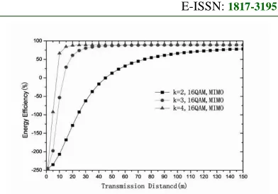
[image:8.612.326.522.77.214.2]Figure 9 shows the energy efficiency curves for different channel path loss factor k, in collaborative node assisting mobile robot multi-antenna receiving scheme. The detection algorithm of robot is based on the approximate ML.
Figure 9: Energy Efficiency Of Collaborative Nodes Assisting Mobile Robot Multi-Antenna Receiving
It can be seen from Figure 9, with the increases of transmission distance, the energy efficiency is higher, and the energy saving effect is more obvious. It can be seen from Figure 9, with the increases of path loss factor k, the energy saving effect increases markedly in the area where transmission distance is relatively small. It means that transmission energy consumption of the collaborative transmission of the assisted node is dominant in the total communication energy consumption, especially for large values of k.
5. CONCLUSION
1) Aiming at the requirements of high-speed data transmission and energy consumption in the case of emergency rescue and real-time detection, a mobile robot-based virtual V-BLAST MIMO transmission scheme in distributed WSNs is proposed. Mobility of robot can reduce the communication distance between the sensor nodes, MIMO-based WSN can use its diversity gain to overcome fading effects and can also use its multiplexing gain to increase the data transmission rate. Simulation results show that the proposed scheme effectively reduces network energy consumption.
2) Aiming at the mobile robot-based virtual V-BLAST MIMO transmission scheme, approximate maximum likelihood algorithm is proposed in this paper. Combined with traditional decoding OSIC algorithm, the vectors need to be detected is reduced, and the computational complexity is decreased greatly. Simulation results show that the low-complexity approximate maximum likelihood detection algorithm further improves energy efficiency, relative to traditional OSIC algorithm.
ACKNOWLEDGEMENTS
[image:8.612.127.275.219.324.2]Jurisdiction of Beijing Municipality (NO. PHR201008434, PHR201106131).
REFERENCES:
[1] Shuguang Cui, A. J. Goldsmith, A. Bahai, “Energy-efficiency of MIMO and cooperative MIMO techniques in sensor networks”, IEEE
Journal on Selected Areas in Communications,
Vol. 22, No. 6, 2004, pp. 1089-1098.
[2] Jie Zhao,Gangfeng Liu, “Multi-robot system for search and exploration in the underground mine disasters based on WSN”, Journal of
China Coal Society, Vol. 34, No.7, 2009, pp.
997-1002.
[3] G. J. Foschini, M. J. Gans. “On limits of wireless communications in a fading environment when using multiple antennas”,
Wireless Personal Communications, No.6,
1998, pp. 311-335.
[4] J. N. Laneman, G. W. Wornell,“Distributed space-time-coded protocols for exploiting cooperative diversity in wireless networks”,
IEEE Transactions on Information Theory, Vol.
49, No. 10, 2003, pp. 2415-2425.
[5] M. Grossglauser, D. Tse, “Mobility increases the capacity of ad-hoc wireless networks”,
IEEE/ACM Transactions on Networking, Vol.
10, No. 4, 2002, pp. 477-486.
[6] Wenchi Cheng, Hailin Zhang, “Approximating maximum likelihood performance reduced dimension VBLAST detection algorithm”,
Science China (Information Sciences), No. 7,
2010, pp. 1439-1445.
[7] Haihong Wang, Xin Wang, Jibo Wei, “Group Maximum Likelihood Detection Algorithm for a 4×4 V-BLAST System”. Signal Processing, Vol. 26, No. 3, 2010, pp. 369-374.
[8] Xiaobei Li, Jieling Wang, Yongshun Zhang, “Joint Detection Algorithm for V-BLAST
System with Higher Performance”, Journal of
System Simulation, Vol. 21, No. 5, 2009, pp.
1387-1389.
[9] T. Cover, A. E. Gamal, Capacity theorems for the relay channel. IEEE Transactions on
Information. Theory, Vol. 25, No. 5, 1979, pp.
572-584.
[10]A. Sendonaris, E. Erkip, B. zhang, “Increasing uplink capacity via user cooperation diversity”, Proceedings of IEEE
International Symposium on Information
Theory, IEEE Information Theory Society,
August 16-21, 1998, pp.156
[11]Wenbai Chen, Wei Li, Xiaopin Zhang, “Complexity reduction ML Detection algorithm for MIMO system”, Journal of
Harbin Institute of Technology, Vol. 44, No. 5,
2012, pp. 1569-1572.
[12]S. K. Jayaweera, “V-BLAST-Based Virtual MIMO for Distributed Wireless Sensor Networks”, IEEE Transactions on
Communications, Vol. 55, No. 10, 2007, pp.