2017 International Conference on Computer Science and Application Engineering (CSAE 2017) ISBN: 978-1-60595-505-6
Research on Multi-beam Scanning and Optimization Technology for
Time Modulated Array
Zengquan Lu, Lilun Zhang*, Dezhi Wang, Yongxian Wang and Min Xu
Academy of Marine Science and Engineering, National University of Defense Technology, 410005 Changsha, Hunan, China
ABSTRACT
Single-frequency signal will generate countless sideband radiation at the harmonic frequencies through the time-modulated array (TMA). Due to the negative impact on the other RF systems, the sideband radiation is usually suppressed. However, this paper focuses on the use of the sideband radiation and the technology of phase-controlled multi-beam scanning, which is based on the countless sideband radiation at the harmonic frequencies. The sideband beam pattern was optimized by the differential evolution algorithm, and the multi-beam scanning technique was realized based on phase weighting to achieve spatial multi-target scanning orientation in a 16-element uniform linear TMA by numerical simulation. Simultaneously the ultra-low sidelobe (SLL) of -40dB and null beamforming of -70dB were realized to suppress the interference.
INTRODUCTION
The phased array is widely used in radar and sonar due to the advantages of being easy to implement low sidelobes, narrow beams, and flexible phase-controlled beam scanning. In 1959, H.E. Shanks and R.W. Bickmore applied the time modulation technology to the antenna design [1]. In 1963, W.H. Kummer and A.T. Villeneuve, for the first time combined the time modulation technique with the antenna array in an 8-unit linear array [2]. The experiment by Liang W has achieved a low sidelobe level of -39.5dB through periodically controlling the ON–OFF states of the high-speed switches in the RF front end. The major advantage of the TMA is that it can obtain a very large dynamic range of the amplitude excitation through a simple periodical ON–OFF modulation to the RF elements, which is difficult from the traditional array [3]. The TMA can increase the design freedom of the phase-controlled array. Compared to the control of phase and amplitude, the control of the switch sequence can be more accurate and convenient. So many experts and scholars start to research the TMA.
we focus on the use of the sideband radiation instead of suppressing. A technology of phase-controlled multi-beam scanning based on the countless sideband radiation at the harmonic frequencies is presented. In addition, in order to get better performance, the realization of ultra-low sidelobe and nulling is necessary.
The paper is organized as follows. Section 2 gives the theory of the proposed method. In Section 3, numeric simulations are provided to examine the feasibility of the proposed method. Section 4 gives the conclusions.
THEORY
Time-modulated Array
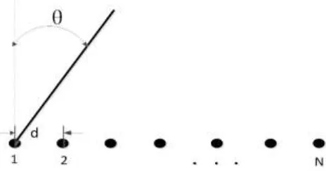
[image:2.612.180.412.264.386.2]Considering an N-element uniform linear TMA with element spacing d, it is shown in the Figure 1.
Figure 1. N-element uniform linear TMA with element spacing d.
The far field radiation expression [2] is
(1)
where is the element radiation factor, is the center frequency, is the excitation amplitude of the nth element, is the phase of the excitation of the nth element, represents the RF switching function of the nth element within a time modulation period . After Fourier expansion the equation (1) can be expressed as
(2)
where is the modulation frequency, is the qth harmonic component of
the nth element.
(3)
Single-frequency signal is decomposed into a center frequency and countless of harmonic frequencies in the frequency domain. The far-field expression of the qth sideband is
Therefore, the expression of any side-frequency signal can be calculated by giving the time-modulated switching function . Then we can analyze the harmonic signal and optimize the sideband beam pattern.
Multi-beam Scanning Based on Phase Weighting
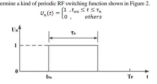
Determine a kind of periodic RF switching function shown in Figure 2.
[image:3.612.129.459.151.328.2](5)
Figure 2. Periodic ON-OFF switch function.
The qth harmonic component of the nth element is
(6)
(7)
Center frequency signal is expressed as:
(8)
frequency is oriented to , the static phase excitation, the starting time and the turn-on time must be designed to satisfy the following equation.
(9)
(10)
Pattern Optimization with Differential Evolution Algorithm
Ultra-low sidelobe can effectively suppress the interference signals. It is also necessary to add the null technology to further suppress the interference signal. We use the differential evolution algorithm to optimize the sidelobe and null. From the equation (7) and (8), it can be seen that the sidelobe and null point of the pattern at the center frequency and is determined by the static amplitude excitation and the turn-on time . Therefore, the differential evolution algorithm optimizes
the parameters , ) to make the main frequency beam and the harmonic
frequency beam achieve the expected sidelobe and null. To achieve the control of the sidelobe and null by differential evolution algorithm, they must be defined in the objective function. We use the absolute value of the difference between highest sidelobe level and the expected sidelobe level as the sidelobe expression in the objective function. The absolute value of the difference between the expected null depth of the given target position and the calculated normalized null depth is used as the null expression in the objective function. The objective function of the differential evolution algorithm can be written as follows.
max des avg des
FITNESS SLL SLL NULL NULL (11)
where α, β is the weighting factor.
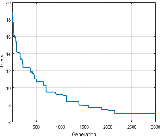
NUMERICAL RESULTS BY MATLAB
In this section, numeric simulations are provided to examinethe effectiveness of the proposed method. Considering 16-element uniform linear TMA, the element spacing d is half of the wavelength. Assuming that the carrier frequency is 1.2 GHz, the expected sidelobe level is -40dB and the expected null depth is below -70dB both at -45°, the first sideband at 45°-60° gets a broad null and the main beam scan to 30°, the first sideband beam scan to -10°. The result of differential evolution is as follows.
Figure 3. The pattern of the main beam and the first sideband beam with DE.
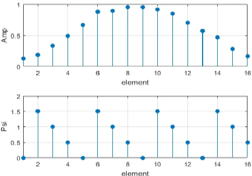
[image:5.612.160.431.389.621.2]Figure 5. Amplitude and phase excitation values.
Figure 5 gives the values of the amplitude and phase of each element and Figure 6 gives the sequence of the RF switch.
Figure 6. The turn-on time and last time of the RF switch.
CONCLUSIONS
[image:6.612.171.414.319.504.2]ACKNOWLEDGEMENT
This study was funded by the National Key Research and Development Project of China (No. 2016YFC1401800) and the Scientific Research Project of NUDT (No.ZK16-03-46, No.ZK16-03-31).
REFERENCES
1. H.E. Shanks and R. W. Bickmore. 1959. “Four-dimensional electromagnetic radiators,” J. Canadian Journal of Physics, 37(3): 263-275.
2. W.H. Kummer, A.T. Villeneuve and T.S. Fong. 1963. “Ultra-low sidelobes from time-modulated arrays,” J. IEEE Trans. on Antennas and Propagation, 11(6): 633-639.
3. Liang W., Jiao Y. C. and Zhang L. 2015. “Sideband suppression in time-modulated linear array by modified differential evolution algorithm,” presented at IEEE International Conference on Communication Problem-Solving, October 16-18, 2015.
4. S. Yang, Y.B. Gan and A. Qing. 2002. “Sideband suppression in time-modulated linear arrays by the differential evolution algorithm,” J. IEEE Antennas Wireless Propag. Letter, 3: 173-175. 5. J. Fondevila, J. C. Bregains, F. Ares and E. Moreno. 2004. “Optimizing uniformly excited linear
arrays through time modulation,” J. IEEE Antennas Wireless Propag. Letter, 3: 298-301.