1
DIGITAL WATERMARKING USING LABVIEW USING DCT ALGORITHM
1
R.Bharathi,2D.Jeyakumari 1,2
M.E.(Communication System), 1
PG Scholar, 2Associate Professor, Department of Electronics and Communication Engineering, RVS College of Engineering and Technology, Coimbatore, TN, India.
ABSTRACT- The paper proposes a blind watermarking algorithm for transferring a real time video. For authentication purpose the concept of logging in is being used. A text watermark is embedded into the streaming video by framing the video as per the requirement. Lab VIEW software is used for watermarking purpose to reduce the complexity. The quality of the watermarked video is checked by comparing the histograms of original video and watermarked video. The quality of video after watermarking indicates that the method used for watermarking is good. The capacity of the algorithm used is very high. This paper proposes a watermarking algorithm for hiding the data securely over the public network. A watermark is embedded into YCBCR (Y-Luminance, CB-Chrominance Blue, and CR-Chrominance Red) colour channels of each video frame using Discrete Cosine Transform with Principle Component Analysis. The process of digital watermarking involves the modification of the original multimedia data to embed a watermark containing a key information such as authentication copyright codes. The embedding method must leaving the original data perceptually unchanged, yet should expose modification which can be detected by using an appropriate extraction algorithm. This method is implemented using LabVIEW.
Keywords- Video Watermarking, Defence Data Records, Principle Component Analysis, DCT.
І.INTRODUCTION:
Digital watermarking can be defined as the process of embedding a certain piece of information (technically known as watermark) into multimedia content including text documents, images, audio or video streams, such that the watermark can be detected or extracted later to make an assertion about the data.In the digital watermarking system, information carrying the watermark is embedded in an original image. The watermarked image is transmitted or stored, and then decoded to be resolved by the receiver. The goal of the watermarking system is not to restrict access to the original image, but to ensure that embedded data remain recoverable. The essential factors of a good watermarking scheme are robustness, imperceptibility, watermark capacity and security. Robustness refers to the ability to survive intentional attacks as well as accidental modifications, for instance, lossy compression, and noise insertion, region cropping, local and
global geometrical transformations.
Imperceptibility or fidelity refers to the perceptual similarity between the watermarked image and its cover image. Watermarking methods with highly complex algorithms that incur more computational costs compared to low complexity. Higher robustness often offsets imperceptibility of a watermark.The number of watermark bits encoded in a message is data payload and the maximum repetition of data payload within an image is the watermark capacity. A watermark may have higher capacity but lower data payload. Higher capacity would comprise its imperceptibility because more modifications to the cover image are needed to embed the watermark.
ІІ.EXISTING SYSTEM:
42 is one of the solutions to this problem. Digital
watermarking has been fascinating many
researchers since last few decades. There is no algorithm that has been accepted universally till
date. Various computational intelligence
methodologies are also being used in digital watermarking to get the desired requirements of watermarking i.e. invisibility and resistance to various attacks. This paper is an attempt to create an optimal image watermarking scheme for copyright protection that can also resist the common attacks on watermarked image. Genetic algorithm has been employed in the proposed algorithm to find the embedding strength of watermark. Genetic algorithm and specially the parameters associated with it have helped in achieving the desired goals of watermarking. DRAWBACKS:
A robust watermark which resists all
attacks is not realistic.
Even when designed under realistic
expectation, watermarking techniques are still vulnerable to attacks by experts. The robustness criteria vary from one
system to another, and recent attacks have shown that all the levels are still inadequate.
ІІІ.PROPOSED SYSTEM:
This paper is about digital audio watermarking technology. It contains using wavelet analysis into digital audio watermarking technology and designing digital audio watermarking system based on Lab VIEW. This paper first introduces the background, the status of development and research of the digital watermarking technology. By combining the relevant knowledge of digital audio, illustrates the features of digital audio watermark technology. Make an evaluation about some digital audio watermarking algorithms.The paper after
introduces the theory about Wavelet
analysis.Wavelet analysis is a signal analysis tool, multi-resolution features in the domain and
43 LITERATURE SURVEY:
An Effective Approach Of Compressing Encrypted Images
In this paper proposing a novel scheme of scalable coding for encrypted images. In the encryption phase, the original pixel values are masked by a modulo-256 addition with nonrandom numbers that are derived from a secret key. After decomposing the encrypted data into a down sampled sub image and several data sets with a multiple-resolution construction, an encoder calculates the sub image and the Hadamard coefficients of each data set to reduce the data amount. Then, the data calculates sub image and coefficients are regarded as a set of bit streams. Because of the hierarchical coding mechanism, the principal original content with higher resolution can be reconstructed when more bit streams are received.
Smoothing And Optimal Compression of Encrypted Gray Scale Images
Government, military and private business amass great deal of confidential images about their patient (in Hospitals),geographical areas (in research),enemy positions (in defense) product, financial-status. Most of this information is now collected and stored on electronic computers and transmitted across network to other computer, if
these confidential images about enemy
positions,patient ,and geographical areas fall into the wrong hands, than such a breach of security could lead to lost of war, wrong treatment etc. Protecting confidential images is an ethical and legal requirement. We store information in computer system in the form of files. File is considered as a basic entity for keeping the information. Therefore the problem of securing image data or information on computer system can be defined as the problem of securing file data. It is worldwide accepted fact that securing file data is very important, in today‟s computing environment. Good encryption makes a source look completely random, traditional algorithms are
unable to compress encrypted data. For this reason, traditional systems make sure to compress before they encrypt. We are using the concept of public key encryption, for the encryption and decryption of image. In this public key‟s of sender and receiver is known to both but private key‟s are kept secret. Neither the security nor the compression efficiency will be sacrificed by performing compression in the encrypted domain. Ensuring Security to the Compressed Sensing Data Using a Steganographic Approach
This paper focuses on the strength of combining cryptography and steganography methods to enhance the security of communication over an open channel. Here the data to be send are secured by using the compressive sensing method and the Singular Value Decomposition (SVD) based embedding method. The data is encrypted using the compressive measurements of the data and the resultant data is embedded in the cover object using the SVD based water mark embedding algorithm. This approach helps to send the secret data after hiding in a cover image. The compressive sensing method helps to compress and encrypt the data in a single step. The proposed system provides more security to the compressed data. This scheme significantly reduces the attacks. This method is very useful to hide the secret images. The results demonstrate that the proposed system is highly efficient and robust.
A Fast Compressive Sensing Based Digital Image Encryption Technique using
Structurally Random Matrices and Arnold Transform
44 with scrambling effect. Second, Arnold transformation is used to give the reduced digital image into more complex form. Then, the complex image is again encrypted by double random phase encoding process embedded with a host image; two random keys with fractional Fourier transform are been used as a secret keys. At the receiver, the decryption process is recovered by using TWIST algorithm. Experimental results including peak-to-peak signal-to-noise ratio between the original and reconstructed image are shown to analyze the validity of this technique and demonstrated our proposed method to be secure, fast, complex and robust.
Scalable Coding of PRNG Encrypted Images This paper proposes a unique scheme of scalable coding for PRNG encrypted images. In the encryption stage, the original pixel values are
masked by a modulo-256 addition with
pseudorandom numbers that are resulting from a secret key. After decomposing the encrypted data into a down sampled sub image and some data sets with a multiple resolution construction, an encoder quantizes the sub image and the Hadamard coefficients of each data set to condense the data quantity. Then, the data of quantized sub image and coefficients are observed as a set of bit streams. At the receiver side, while a sub image is decrypted to provide the uneven information of the original content, the quantized coefficients can be used to reconstruct the detailed content with an iteratively updating procedure. Because of the hierarchical coding mechanism, the principal original content with advanced resolution can be reconstructed when more bit streams are received. A number of works on compressing encrypted images have been also presented. When a sender encrypts an original image for privacy protection, a channel provider without the knowledge of a cryptographic key and original content may tend to reduce the data amount due to the limited channel resource.
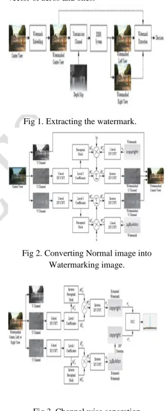
WATERMARK PREPERATION:
The medical information is inserted into a text file .This text file is then converted into binary form, according to text file generate a watermark image and then convert the binary image into vector of zeros and ones.
Fig 1. Extracting the watermark.
Fig 2. Converting Normal image into Watermarking image.
45 DATA EXTRACTION PROCESS:
Initially convert the watermarked video into Y, Cb, Crframe. For each Y,Cb,Cr component apply DWT to decompose the channel into 64 multi-resolution sub-bands. Divide each sub-band into n x n non-overlapping blocks. Using second secret key extract the watermark. The extracted watermark is compared with the original watermark by computing the similarity between them.
PROPOSED TECHNIQUE USED
2D Discrete Cosine Transforms.
Adiscrete cosine transform (DCT)
expresses a finite sequence of data points in terms of a sum of cosine functions oscillating at different frequencies. DCTs are important to numerous applications in science and engineering,
fromlossy compression ofaudio (e.g. MP3)
and images (e.g. JPEG) (where small high-frequency components can be discarded), to spectral methods for the numerical solution of partial differential equations.
The basic operation of the DCT is as follows:
The input image is N by M;
F (i,j) is the intensity of the pixel in row i and column j;
F (u, v) is the DCT coefficient in row k1 and column k2 of the DCT matrix.
For most images, much of the signal energy lies at low frequencies; these appear in the upper left corner of the DCT.
Compression is achieved since the lower right values represent higher frequencies, and are often small - small enough to be neglected with little visible distortion.
The DCT input is an 8 by 8 array of integers. This array contains each pixel's gray scale level;
8 bit pixels have levels from 0 to 255. Compression allows increased throughput through transmission medium.
Video and audio compression makes multimedia systems very efficient
Increases CPU bandwidth Higher video frame rates Better audio quality
Enables multimedia interactivity
DCT and IDCT are widely used in video and audio compression
DCT (DISCRETE COSINE TRANSFORM):
X= DCT (video/audio input)
Returns the discrete cosine transform of „video/audio input‟
Can be referred to as the even part of the Fourier series
Converts an image or audio block into it‟s equivalent frequency coefficients
CONCEPT:
The DCT transform of an image brings out a set of numbers called coefficients.
A coefficient‟s usefulness is determined by its variance over a set of images as in video‟s case.
If a coefficient has a lot of variance over a set, then it cannot be removed without affecting the picture quality
EQUATIONS:
One-Dimensional DCT Equation N-1
Xc(k) = (1/N) Σ Xn cos(k2πn/N), n=0
wherek = 0, 1, 2, …, N-1
46 N-1 N-1
F[u, v] = 1/N2 Σ Σ f[m, n] cos[ (2m + 1)uπ/ 2N] cos[ (2n + 1)vπ/2N ]
m=0 n=0
where u, v = discrete frequency variables (0, 1, 2, …, N - 1),
f[m, n] = N by N image pixels(0, 1, 2, …, N - 1), andF[u, v] = the DCT result
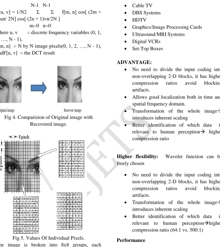
Fig 4. Comparision of Original image with Recovered image.
Fig 5. Values Of Individual Pixels.
The image is broken into 8x8 groups, each containing 64 pixels. Three of these 8x8 groups are enlarged in this figure, showing the values of the individual pixels, a single byte value between 0 and 255.
APPLICATIONS:
DVD/Video CD Players
Cable TV
DBS Systems
HDTV
Graphics/Image Processing Cards Ultrasound/MRI Systems
Digital VCRs Set-Top Boxes
ADVANTAGE:
No need to divide the input coding into non-overlapping 2-D blocks, it has higher compression ratios avoid blocking artifacts.
Allows good localization both in time and spatial frequency domain.
Transformation of the whole image introduces inherent scaling
Better identification of which data is relevant to human perception higher compression ratio
Higher flexibility: Wavelet function can be freely chosen
No need to divide the input coding into non-overlapping 2-D blocks, it has higher compression ratios avoid blocking artifacts.
Transformation of the whole image introduces inherent scaling
Better identification of which data is relevant to human perceptionhigher compression ratio (64:1 vs. 500:1)
Performance
Peak Signal to Noise ratio used to be a measure of image quality.
47 images are virtually indistinguishable by human observers
DIGITAL IMAGE:
A digital image is a matrix representation of a two-dimensional image
Gray scale image Colour image
(Black and White)
HISTOGRAM EQUALISATION:
Image processing of contrast adjustment using the image‟s histogram
Original Equalized
TYPES:(1) GLOBAL HISTOGRAMEQUALISATION
:
Original
Transformatiom Function.
CDF
48 Equalized image
(2) BIHISTORY HISTOGRAM EQUALISATION:
Histogram equalised separately around mean. Thus conserved the mean
Histogram Image is separated by a line
Left part Right part
Converting Histogram image into Mean
Separately.
Merging the Mean
OUTPUT:
BIHISTOGRAM EQUALIZATION WITH A PLATEAU LIMIT
Bihistogram
49 Clipping
TL PLATEAU LIMITS FOR LOWER
HISTOGRAM.
TU PLATEAU LIMITS FOR UPPER
HISTOGRAM.
OUTPUT:
SYSTEM DESIGN
GENERAL
Design Engineering deals with the various UML [Unified Modeling language] diagrams for the implementation of project. Design is a meaningful engineering representation of a thing that is to be built. Software design is a process through which the requirements are translated into representation of the software. Design is the place where quality is rendered in software engineering. Design is the means to accurately translate customer requirements into finished product.
SOFTWARE USED:
The LabVIEW is a high-performance language for technical computing integrates computation, visualization, and programming in an easy-to-use environment where problems and solutions are expressed in familiar mathematical notation.
Data Exploration, Acquisition, Analyzing &Visualization
Image Processing
Analyzing of algorithmic designing and development
Mathematical functions and Computational functions
Simulating problems prototyping and modeling
Application development programming using GUI building environment
Using LabVIEW, you can solve technical computing problems faster than with traditional programming languages, such as C, C++, and FORTRAN.
HARDWARE REQUIREMENTS:
Biometrics Scanner or High Resolution Camera.
PC with core i5 processor and 8 GB RAM (Recommended)
SOFTWARE REQUIREMENTS:
NI LabVIEW 2013 or Higher
NI Vision Development Toolkit
PROCEDURE:
TRAINING THE TEMPLATE.
First Templates need to be captured in order to train the images. Template images must be of high resolution with .bmp extension for accurate processing.
Now captured template will be converted into grayscale images if needed. Because if biometric scanner is used to capture the image then there is no need of conversion to Grayscale.
After conversion Region of Interest (ROI) should be selected. i.e., Palm section must be extracted from the template.
Using 3 algorithms learning of the template is done.
Low
Discrepancy
50 Sampling (1) algorithm extracts the most
significant information to represent an image. If your template contains large regions of similar grayscale information, a wide aspect ratio, or is very small, use one of the pyramidal
matching algorithms
instead.
Now in order to avoid the copying/theft of the template we are converting that template into a variant then saving it.
DATAFLOW PROGRAMMING MODEL
Due to its thorough adoption of a data-flow programming model as opposed to the sequential ordering of arbitrary commands like most other (usually text-based) languages there is a very real barrier to many people who attempt to apply
already-learned principles from other
programming approaches to LabVIEW. The inherent parallel nature of the execution of LabVIEW code is a perennial source of confusion among those who are accustomed to other approaches. Due to this, most opinions tend to be highly polarized with people either being extremely fond of it or being extremely hostile to it.
RUN-TIME ENVIRONMENT:
Compiled executables produced by version 6.0 and later of the Application Builder are not truly standalone in that they also require the LabVIEW run-time engine be installed on any target computer which runs the application. The use of standard controls requires a run-time library for any language. All major operating systems supply the required libraries for common languages such as C. However, the run-time required for LabVIEW is not supplied with any operating system and has to be specifically installed by the administrator or user. This can
cause problems if an application is distributed to a user who may be prepared to run the application but does not have the inclination or permission to install additional files on the host system prior to running the executable.
PERFORMANCE
LabVIEW makes it difficult to get machine or hardware limited performance and tends to produce applications that are slower than hand coded native languages such as C. High performance can be achieved while using multi-core machines or dedicated toolkits for specific
operations. LabVIEW makes multi-core
programming much simpler and faster than text based languages.
Algorithm implementation
Gradient computation
The first step of calculation in many feature detectors in image pre-processing is to ensure normalized color and gamma values. As Dalal and Triggs point out, however, this step can be omitted in HOG descriptor computation, as the ensuing descriptor normalization essentially achieves the same result. Image pre-processing thus provides little impact on performance. Instead, the first step of calculation is the computation of the gradient values. The most common method is to apply the 1-D centered, point discrete derivative mask in one or both of the horizontal and vertical directions. Specifically, this method requires filtering the color or intensity data of the image with the following filter kernels:
51 applying the derivative mask, but similarly found that omission of any smoothing performed better in practice.
Orientation binning
The second step of calculation is creating the cell histograms. Each pixel within the cell casts a weighted vote for an orientation-based histogram channel based on the values found in the gradient computation. The cells themselves can either be rectangular or radial in shape, and the histogram channels are evenly spread over 0 to 180 degrees or 0 to 360 degrees, depending on whether the gradient is “unsigned” or “signed”. Dalal and Triggs found that unsigned gradients used in conjunction with 9 histogram channels performed best in their human detection experiments. As for the vote weight, pixel contribution can either be the gradient magnitude itself, or some function of the magnitude. In tests, the gradient magnitude itself generally produces the best results. Other options for the vote weight could include the square root or square of the gradient magnitude, or some clipped version of the magnitude.
Descriptor blocks
To account for changes in illumination and contrast, the gradient strengths must be locally normalized, which requires grouping the cells together into larger, spatially connected blocks. The HOG descriptor is then the concatenated vector of the components of the normalized cell histograms from all of the block regions. These blocks typically overlap, meaning that each cell contributes more than once to the final descriptor. Two main block geometries exist: rectangular R-HOG blocks and circular C-R-HOG blocks. R-R-HOG blocks are generally square grids, represented by three parameters: the number of cells per block, the number of pixels per cell, and the number of channels per cell histogram. In the Dalal and
Triggs human detection experiment, the optimal parameters were found to be four 8x8 pixels cells per block (16x16 pixels per block) with 9 histogram channels. Moreover, they found that some minor improvement in performance could be gained by applying a Gaussian spatial window within each block before tabulating histogram votes in order to weight pixels around the edge of the blocks less.
SOFTWARE TESTING GENERAL
The purpose of testing is to discover errors. Testing is the process of trying to discover every conceivable fault or weakness in a work product. It provides a way to check the functionality of components, sub assemblies, assemblies and/or a finished product It is the process of exercising software with the intent of ensuring that the Software system meets its requirements and user expectations and does not fail in an unacceptable manner. There are various types of test. Each test type addresses a specific testing requirement.
DEVELOPING METHODOLOGIES
The test process is initiated by developing a comprehensive plan to test the general functionality and special features on a variety of platform combinations. Strict quality control procedures are used.
The process verifies that the application meets the requirements specified in the system requirements document and is bug free. The following are the considerations used to develop the framework from developing the testing methodologies.
TYPES OF TESTS Unit testing
52 internal code flow should be validated. It is the testing of individual software units of the application .it is done after the completion of an individual unit before integration. This is a structural testing, that relies on knowledge of its construction and is invasive. Unit tests perform basic tests at component level and test a specific business process, application, and/or system configuration. Unit tests ensure that each unique path of a business process performs accurately to the documented specifications and contains clearly defined inputs and expected results.
Functional test
Functional tests provide systematic demonstrations that functions tested are available as specified by the business and technical requirements, system documentation, and user manuals.
Functional testing is centered on the following items:
Valid Input : identified classes of valid input must be accepted.
Invalid Input : identified classes of invalid input must be rejected.
Functions : identified functions must be exercised.
Output : identified classes of application outputs must be exercised.
Systems/Procedures: interfacing systems or procedures must be invoked.
System Test
System testing ensures that the entire integrated software system meets requirements. It tests a configuration to ensure known and predictable results. An example of system testing is the configuration oriented system integration test. System testing is based on process descriptions and flows, emphasizing pre-driven process links and integration points.
Performance Test
The Performance test ensures that the output be produced within the time limits and the time taken by the system for compiling, giving
response to the users and request being send to the system for to retrieve the results.
Integration Testing
Software integration testing is the incremental integration testing of two or more integrated software components on a single platform to produce failures caused by interface defects.
The task of the integration test is to check that components or software applications, e.g. components in a software system or – one step up – software applications at the company level – interact without error.
Acceptance Testing
User Acceptance Testing is a critical phase of any project and requires significant participation by the end user. It also ensures that the system meets the functional requirements. Acceptance testing for Data Synchronization:
The Acknowledgements will be received by the Sender Node after the Packets are received by the Destination Node
The Route add operation is done only when there is a Route request in need
The Status of Nodes information is done automatically in the Cache Updating process
Build the test plan
Any project can be divided into units that can be further performed for detailed processing. Then a testing strategy for each of this unit is carried out. Unit testing helps to identity the possible bugs in the individual component, so the component that has bugs can be identified and can be rectified from errors.
APPLICATION:
It can be applied to the following areas,
Medical Applications
Army Applications.
53 In the first part of this paper we have developed algorithms image transmission via LabVIEW. The use of these algorithms can send an image via a local network and also via a wireless network, and more specifically the Internet. The basic idea is to insert a watermark in the low frequency part of the discrete wavelet transform of an image host, Then we try to diminish the value of parameter robustness alpha whose objective to have a fragile watermarking to verify that the image has not been modified or to ensure the authentication of the image. This new
method is performance in terms of
imperceptibility and maintains a high quality watermarked images from the calculated values of PSNR. Then we propose to illustrate the extension of this technique to the image of watermarking color that represents the information support most frequently used.
REFERENCES:
[1] Y. H. Lin and J. L. Wu, “A digital blind watermarking for depth-imagebased rendering 3D images,” IEEE Transactions on Broadcasting, vol.57, no. 2, pp. 602–611, 2011.
[2] H. D. Kim, J. W. Lee, T. W. Oh, and H. K. Lee, “Robust DTCWT watermarking for DIBR 3D images,” IEEE Transactions onBroadcasting, vol. 58, no. 4, pp. 533–543, 2012.
[3] P. Ndjiki-Nya, M. Koppel, D. Doshkov, H. Lakshman, P. Merkle, K. Muller, and T. Wiegand, “Depth image-based rendering with advanced texture synthesis for 3-D video,” IEEE
Transactions onMultimedia, vol. 13, no. 3, pp.
453–465, Jun. 2011.
[4] J. Lei, C. Zhang, Y. Fang, Z. Gu, N. Ling, and C. Hou, “Depth sensation enhancement for multiple virtual view rendering,” IEEE
Transactionson Multimedia, vol. 17, no. 4, pp.
457–469, Apr. 2015.
[5] C. Fehn, “Depth-image-based rendering (DIBR), compression, and transmission for a new
approach on 3D-TV,” Proc. SPIE
StereoscopicDisplays and Virtual Reality Systems XI, vol. 5291, pp. 93–104, 2004.
[6] L. Zhang and W. J. Tam, “Stereoscopic image generation based on depth images for 3D TV,”
IEEE Transactions on Broadcasting, vol. 51, no.
2, pp. 191–199, 2005.
[7] M. J. Lee, K. S. Kim, and H. K. Lee, “Digital cinema watermarking for estimating the position of the pirate,” IEEE Transactions on Multimedia, vol. 12, no. 7, pp. 605–621, Nov. 2010.
[8] G. C. Langelaar, I. Setyawan, and R. L. Lagendijk, “Watermarking digital image and video data. a state-of-the-art overview,” IEEE
SignalProcessing Magazine, vol. 17, pp. 20–46,
2000.
[9] G. Do¨err and J. L. Dugelay, “A guide tour of video watermarking,” Signal Processing: Image
Communication, vol. 18, no. 4, pp. 263–282, 2003.
[10] M. D. Swanson, M. Kobayashi, and A. H.
Tewfik, “Multimedia dataembedding and