Iranian Journal of Electrical and Electronic Engineering, Vol. 16, No. 1, March 2020 114
Optimal Shaping of Non-Conventional Permanent Magnet
Geometries for Synchronous Motors via Surrogate Modeling
and Multi-Objective Optimization Approach
A. Nobahari*, M. R. Mosavi*(C.A.) and A. Vahedi*
Abstract: A methodology is proposed for optimal shaping of permanent magnets with non-conventional and complex geometries, used in synchronous motors. The algorithm includes artificial neural network-based surrogate model and multi-objective search based optimization method that will lead to Pareto front solutions. An interior permanent magnet topology with crescent-shaped magnets is also introduced as the case study, on which the proposed optimal shaping methodology is applied. Produced torque per magnets mass and percentage torque ripple are considered as the objectives, in order to take both performance and cost into account. Multi-layer perceptron architecture used to create the approximated model is trained to fit the samples collected via time-stepping finite element simulations. The methodology can be easily generalized to offer a fast and accurate method to optimally define arbitrary permanent magnet shape parameters in various synchronous motors.
Keywords: Permanent Magnet Shaping, Surrogate Model, Artificial Neural Network, Multi-Objective Optimization.
1 Introduction1
ERMANENT magnet motors are used widely for commercial electric and hybrid electric vehicles [1, 2]. These motors are known mostly for their high efficiency and high torque capability characteristics. Recently, several researches have been conducted in order to achieve an optimum design of Permanent Magnet Synchronous Motors (PMSMs) using various approaches. A typical design optimization method can be characterized based on its two principle phases: (1) the modeling procedure and (2) the searching fashion to find the best design solution. To deal with design problems, one can find various modeling methods for electrical machines, which can be categorized in two groups. The first category, which
Iranian Journal of Electrical and Electronic Engineering, 2020. Paper first received 21 October 2018, revised 11 November 2019, and accepted 16 November 2019.
* The authors are with the School of Electrical Engineering, Iran University of Science and Technology, Narmak, Tehran 13114-16846, Iran.
E-mails: [email protected], [email protected] and [email protected].
Corresponding Author: M. R. Mosavi.
also can be known as conventional models, includes physic-based methods that try to represent and solve the field equations (i.e., Maxwell equations) in the machine under study. These methods can be analytical (e.g., formal solutions of Maxwell equations in constant permeability regions), semi-analytical (e.g., magnetic equivalent network) or numerical (e.g., Finite Elements Analysis (FEA)) that compromise between the computation cost and the accuracy [3]. Although, the use of these models is essential at the initial design steps, they have been utilized widely at the optimization level, too [4-9]. Whilst, developing an analytical model is subjected to several restrictions, FEA not only can offer the highest accuracy but also can easily represent arbitrary complex geometries. However, using such model within a search based optimization procedure may be too much time consuming and hence practically impossible.
The next category of modeling methods has been developed to overcome the mentioned challenges. This alternative approach, called surrogate modeling methods, consists of mathematical-based models that can be derived using Design of Experiments (DOE) techniques. In order to construct a surrogate model two steps have to be performed: (1) samples collection and
P
Iranian Journal of Electrical and Electronic Engineering, Vol. 16, No. 1, March 2020 115
(2) function approximation or fitting [10]. According to the DOE techniques there are several principles to define the samples required to create the dataset, including factor design [11], Latin hypercube design [12, 13], orthogonal design [14, 15], and etc. Next, the fitting process must be done using certain mathematical models, e.g., response surface [16, 17], Kriging model [18, 19], Artificial Neural Networks (ANN) [11, 20], etc.
After developing an appropriate model by trading off between its accuracy and computational cost, the global best design must be searched among the feasible solutions. To this end, intelligent optimization methods (e.g., Genetic Algorithm (GA) and Particle Swarm Optimization (PSO)) have been utilized widely in the recent researches. Design optimization of electrical machines is often a multi-criteria problem, because several characteristics vary in a conflicting manner by changing the design variables. These multi-criteria problems can be represented via either a single-objective problem, as done in [21], or a multi-single-objective problem. The last one, which has attracted much attention in the recent years, can be solved through different methods such as Pareto approach [20], multi-criteria decision making methods [22], etc.
Permanent Magnets (PMs) design is one of the most important steps of designing the Permanent Magnet Synchronous Motors (PMSMs). Conventionally, simple basis geometries are considered for PMs (e.g., a rectangular shape) in order to simplify the construction process. However, better performance characteristics may be achieved by defining more complex basis geometries [23]. Hence, the problem will be complicated due to the need for developing new models and the necessity for defining more geometrical variables.
In this paper, a new framework is introduced for shape optimization of PMs with non-conventional geometries. The algorithm includes using an ANN as the basis function to create a surrogate model, and employing a multi-objective Pareto optimization method to calculate the best set of possible designs (Pareto solutions) according to the defined objectives. Moreover, the introduced method is applied to an Interior PMSM (IPMSM), the specifications of which are appropriate for small electric vehicle applications. The studied IPMSM has a distributed armature winding and a crescent PM shape, as an example of non-conventional basis geometry. An advantage of the crescent PM shape can be the relatively larger saliency ratio, which can lead to more reluctance torque and better field weakening capability. Also, the produced torque per PMs mass as well as the percent torque ripple are considered as the optimization objectives, so that both the performance and the cost are taken into account. PMs sizing parameters are the only variables of the optimization problem. The paper will go on by a brief representation about the studied IPMSM and the basis
analytical sizing equations, following by the detailed contents about the optimization procedure, including modeling and multi-objective optimization routes, in the third section. Finally, the results will be illustrated in the fourth section along with the required discussions.
2 Analytical Design
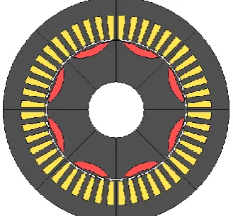
A 2-D view of the proposed IPMSM is illustrated in Fig. 1. Analytical models are usually preferred for initial design steps. Hence, a simplified magnetic circuit model is used to specify the initial design. Main dimensions (i.e., stack length and core diameters) as well as the whole stator design will be considered finality, while the PMs design will be optimized at the next part. The sizing procedure of the IPMSM starts with the main dimensions using (1) [24]:
2 2
tan / 60
n r
w
P D L
K n
(1)
In (1), Dr and L are rotor diameter and stack length,
respectively, which are known as the main dimensions of a radial air gap motor. Also, Pn, η and n are nominal
power, efficiency and synchronous base speed (in RPM), respectively. The winding factor (Kw) equals to
the distribution factor (full pitch winding is assumed) and the mean value of the rotor tangential Maxwell stress (σtan) can be calculated as a function of the
magnetic loading (Bˆg) and electrical loading (A):
tan
1 ˆ
2 ABg
(2)
Tangential Maxwell stress that is restricted by the electrical and magnetic limitations produces the torque (T) when acting upon the rotor surface:
tan
(2 ) 4 r r
T D D L (3)
Stator core detailed parameters such as tooth width and yoke height are defined, so that the desired
Fig. 1 2-D representation of the studied motor.
Iranian Journal of Electrical and Electronic Engineering, Vol. 16, No. 1, March 2020 116
magnetic flux density in each part is satisfied. New crescent-shaped PMs with parallel magnetization are adopted in the rotor. Parallel magnetization is usually considered for AC drives rather than the radial pattern, since they can produce more sinusoidal air-gap flux density [25].
Table 1 shows the desired IPMSM specifications for a small electric vehicle such as a scooter.
Certain design of PMs can be achieved by defining four parameters as shown in Fig. 2(a). It was found out that torque ripple can be significantly affected by applying additional gap as depicted in Fig. 2(b). This can be implemented by shifting the PMs through the radial direction, so that the PM volume kept unchanged, although the resultant variation of the mean torque value is strictly non-linear. Therefore, there are five parameters to be determined in order to fulfillment the design of PMs. However the sensitivity levels of the objectives, especially the torque profile, to all
Table 1 Specifications of the studied IPMSM.
Parameter Value Base speed [RPM] 3500 Rated power [W] 5000 Rated current [A] 14.8 Pole numbers 8 Stator slot numbers 48
(a)
(b)
Fig. 2 Crescent PM geometrical parameters to be defined.
parameters are not the same. Hence, in order to reduce the size of the dataset required for the optimization step, three parameters are selected to which the variation rate of the output torque characteristics is more than the others. It should be noted that this act is done only to reduce the size of calculations, and does not relevance to the optimal design methodology.
3 Optimization Procedure
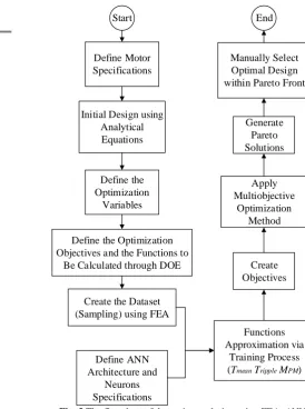
As mentioned earlier, a multi-objective optimization method combined with a surrogate model of the IPMSM is utilized to calculate the Pareto design solutions. The flowchart shown in Fig .3 describes the sequential procedure.
3.1 Surrogate Modeling Procedure
ANN is used widely for regression applications in different areas of science and engineering. Modeling the behavior of a specific characteristic of an electric motor as a function of several structural variables can also be considered as a regression process. For these applications, ANN parameters (i.e., the values of weights and biases) are calculated mostly via supervised
Define Motor Specifications
Initial Design using Analytical Equations
Define the Optimization
Variables
Define the Optimization Objectives and the Functions to
Be Calculated through DOE
Create the Dataset (Sampling) using FEA
Define ANN Architecture and
Neurons Specifications
Functions Approximation via
Training Process (Tmean Tripple MPM)
Create Objectives
Apply Multiobjective
Optimization Method Generate
Pareto Solutions Manually Select Optimal Design within Pareto Front
Start End
Fig. 3 The flowchart of the optimum design using FEA, ANN and NSGA II.
Iranian Journal of Electrical and Electronic Engineering, Vol. 16, No. 1, March 2020 117
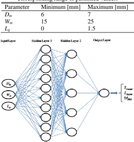
learning methods, in which a proper dataset needs to be prepared. Due to the high achievable accuracy and thanks to the available commercial software packages, FEA can be used to provide the dataset. In other words, FEA have been considered as an excellent valid model that can roughly represent the experiments [11, 20]. In this paper, a full factor approach is used to collect the samples by 2-D time-stepping FEA, where the three optimization variables are discretized within their permitted values (as shown in Table 2) and 847 samples are collected. The parameters R1 and R2 are fixed at 30mm and 50mm, respectively. Three Multi-Layer Perceptron (MLP) ANNs are used to approximate the variations of three functions: mean torque (Tmean),
torque ripple (Tripple%) and PMs mass (MPM), separately.
All networks are formed by one input layer, two hidden layers and one output layer, while the number of neurons of the hidden layers is determined differently for each network, depending on the behavior of the corresponding function. Indeed, the size of the ANN parameters (i.e., number of layers and neurons) is determined via trial and error attempts. Linear function is used as the activation function of the output layer, while hyperbolic tangent is defined for hidden layers. Fig. 4 illustrates the ANNs architecture and the mathematical relationship between optimization variables and network output is presented in (4).
2 1 3
1 1 1
tanh tanh
N N
i i ji j pj p
i j p
Y W b W b W U
(4)where U, W, b and Y are inputs, weights, biases and outputs, respectively. Also, N1 and N2 indicate number
of neurons in first and second hidden layers.
Table 2 Three optimization design variables and the corresponding range of permitted values. Parameter Minimum [mm] Maximum [mm]
Dm 6 7
Wm 15 25
Lg 0 1.5
Fig. 4 MLP NN architecture used as the basis function of the approximated model.
3.2 Multi-Objective Optimization
As mentioned previously, the optimization design of electrical machines is usually a multi-objective task, since the objective functions to be optimized are often in conflict with each other. Among various existing multi-objective optimization approaches, which are surveyed in [26], Pareto method is used widely, since it can provide a set of optimal solutions in which all the objective functions are considered with the same significance. Hence, the designer is able to pick the final design within the set of “best solutions” considering the desired criteria.
To start the optimization process, first, the optimization problem should be properly expressed. In this study, the optimization problem can be formulated as:
([ ])
Max ([ ]) &
Min %
[ ] [ , , ]
mean
PM
ripple
m m g
T X
M X
T
X D W L (5)
where max min % 100 ripple mean T T T T
(6)
It can see that two objective functions are assumed. Next, the variables domain (see Table 2) must be searched to find the optimal schemes. To this task, the Pareto approach can be applied within the intelligent optimization methods. Among different Pareto-based intelligent optimization methods, the Non-dominated Sorting GA (NSGA II) is utilized in this paper. Some detailed parameters of the applied NSGA II are presented in Table 3.
4 Results
Applying the simple sizing procedure results in a preliminary design, the characteristics of which are shown in Table 4. The nominal phase Electro-Motive Force (EMF) is considered to be 120V. As mentioned, 847 samples are collected via 2D- FEA, where only one pole partial model can be calculated due to the existing symmetry (as shown in Fig. 5) that leads to considerable computation cost reduction.
Optimization process starts with training three MLP ANNs to approximately modeling three characteristic
Table 3 Detailed parameters of the applied NSGA II.
NSGA II parameters Value/Type
Population size 100
Selection type Tournament
Crossover type Single point
Mutation type Uniform
Distance measure type Crowding distance
Iranian Journal of Electrical and Electronic Engineering, Vol. 16, No. 1, March 2020 118
functions Tmean, Tripple, MPM. 95 percent of the dataset are
selected randomly, to train the network and the rest of the samples are used to evaluate the network performance. Fig. 6 shows the results of training and testing three networks. The Mean-Squared Error (MSE) criterion is employed to verify the constructed models. As can be seen the best fitting is obtained for MPM function, while Tripple function is modeled with larger
MSE, for both train and test levels. This can be justified by the existing difference in the behavior of three characteristics, where the Tripple variations have the most
complexity.
The objectives introduced in (5) can be created by
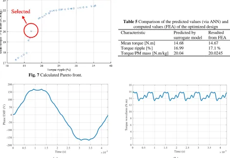
combining the networks output. Applying the NSGA II will lead to the set of the best non-dominated solutions. Fig. 7 illustrates the obtained Pareto front.
Usually, the final design is selected manually within the Pareto set by the experts. Here, a typical design is selected as depicted in Fig. 7 to evaluate the design process. The value of three variables corresponding to the selected solution are Dm = 6.42mm, Wm = 17.57mm and Lg = 0.37mm, respectively. Table 5 compares the resulted and predicted values of Tmean,
Tripple and Tmean/MPM calculated by FEA software package and ANNs, respectively, to demonstrate the validity of the optimization procedure. Moreover, the produced torque waveform and induced phase voltage of the final design are shown in Fig. 8.
Table 4 Constant design parameters.
Parameter Value [mm]
Stator outer diameter 200
Stack length 74
Air-gap length 1
Shaft diameter 50
R1 30
R2 50
(a) (b)
Fig. 5 Partial geometry FE modeling to save the computation time and memory. a) Calculated mesh and b) Magnetic flux density distribution are illustrated for a typical sample.
Fig. 6 Training and testing results of three networks, evaluated by MSE criterion, for “Train” and “Test” sets.
Iranian Journal of Electrical and Electronic Engineering, Vol. 16, No. 1, March 2020 119
Table 5 Comparison of the predicted values (via ANN) and computed values (FEA) of the optimized design Characteristic Predicted by
surrogate model
Resulted from FEA
Mean torque [N.m] 14.68 14.67
Torque ripple [%] 16.99 17.1 %
Torque/PM mass [N.m/kg] 20.04 20.0245
Fig. 7 Calculated Pareto front.
(a) (b)
Fig. 8 a) Phase EMF and b) produced torque of the optimum design.
5 Conclusions
A new PM shaping algorithm was proposed, which can be easily adopted to optimally calculate the geometrical parameters of various PM shapes in synchronous motors. More complicated PM geometries can result in better motor performances; if proper basis geometry is define. In this paper, crescent-basis geometry is introduced only to show the proposed shaping methodology. The algorithm also leads to a set of Pareto optimal designs. Provided that a proper set of samples are collected, the approximated model can present a competitive accuracy to FE model, while it is significantly superior in term of computation speed, which is exactly an important issue in search based optimizations. Future works could extend to investigate other types of ANN architectures and intelligent optimization methods.
References
[1] A. M. El-Refaie, “Motors/generators for traction/propulsion applications: A review,” IEEE Vehicular Technology Magazine,Vol. 8, pp. 90–99, 2013.
[2] B. Sarlioglu, C. T. Morris, D. Han, and S. Li, “Driving toward accessibility: a review of technological improvements for electric machines, power electronics, and batteries for electric and hybrid vehicles,” IEEE Industry Applications Magazine, Vol. 23, pp. 14–25, 2017.
[3] H. Tiegna, Y. Amara, and G. Barakat, “Overview of analytical models of permanent magnet electrical machines for analysis and design purposes,”
Mathematics and Computers in Simulation, Vol. 90, pp. 162–177, 2013.
[4] F. Scuiller, “Magnet shape optimization to reduce pulsating torque for a five-phase permanent-magnet low-speed machine,” IEEE Transactions on Magnetics,Vol. 50, pp. 1–9, 2014.
[5] Z. Chen, C. Xia, Q. Geng, and Y. Yan, “Modeling and analyzing of surface-mounted permanent-magnet synchronous machines with optimized magnetic pole shape,” IEEE Transactions on Magnetics, Vol. 50, pp. 1–4, 2014.
[6] F. Safaei, A. A. Suratgar, A. Afshar, and M. Mirsalim, “Characteristics optimization of the maglev train hybrid suspension system using genetic algorithm,” IEEE Transactions on Energy Conversion, Vol. 30, pp. 1163–1170, 2015.
Iranian Journal of Electrical and Electronic Engineering, Vol. 16, No. 1, March 2020 120
[7] G. Y. Sizov, P. Zhang, D. M. Ionel, N. A. Demerdash, and M. Rosu, “Automated multi-objective design optimization of PM AC machines using computationally efficient FEA and differential evolution,” IEEE Transactions on Industry Applications, Vol. 49, pp. 2086-2096, 2013. [8] P. Zhang, D. M. Ionel, and N. A. Demerdash,
“Saliency ratio and power factor of IPM motors with distributed windings optimally designed for high efficiency and low-cost applications,” IEEE Transactions on Industry Applications, Vol. 52, pp. 4730–4739, 2016.
[9] J. H. Lee, J. Y. Song, D. W. Kim, J. W. Kim, Y. J. Kim, and S. Y. Jung, “Particle swarm optimization algorithm with intelligent particle number control for optimal design of electric machines,” IEEE Transactions on Industrial Electronics, Vol. 65, pp. 1791–1798, 2018.
[10]G. Lei, J. Zhu, and Y. Guo, Multidisciplinary design optimization methods for electrical machines and drive systems. Springer, 2016.
[11]M. N. Azari, M. Mirsalim, S. M. A. Pahnehkolaei, and S. Mohammadi, “Optimum design of a line-start permanent-magnet motor with slotted solid rotor using neural network and imperialist competitive algorithm,” IET Electric Power Applications,
Vol. 11, pp. 1–8, 2017.
[12]P. S. Shin, S. H. Woo, and C. S. Koh, “An optimal design of large scale permanent magnet pole shape using adaptive response surface method with latin hypercube sampling strategy,” IEEE Transactions on Magnetics, Vol. 45, pp. 1214–1217, 2009. [13]C. Ma and L. Qu, “Multiobjective optimization of
switched reluctance motors based on design of experiments and particle swarm optimization,” IEEE Transactions on Energy Conversion, Vol. 30, pp. 1144–1153, 2015.
[14]H. Azizi and A. Vahedi, “Sensitivity analysis and optimum design for the stator of synchronous reluctance machines using the coupled finite element and Taguchi methods,” Turkish Journal of Electrical Engineering & Computer Sciences, Vol. 23, pp. 38– 51, 2015.
[15]J. Song, F. Dong, J. Zhao, S. Lu, S. Dou, and H. Wang, “Optimal design of permanent magnet linear synchronous motors based on Taguchi method,” IET Electric Power Applications, Vol. 11, pp. 41–48, 2017.
[16]S. Saha, G. D. Choi, and Y. H. Cho, “Optimal rotor shape design of LSPM with efficiency and power factor improvement using response surface methodology,” IEEE Transactions on Magnetics,
Vol. 51, pp. 1–4, 2015.
[17]Z. Xiang, X. Zhu, L. Quan, Y. Du, C. Zhang, and D. Fan, “Multilevel design optimization and operation of a brushless double mechanical port flux-switching permanent-magnet motor,” IEEE Transactions on Industrial Electronics, Vol. 63, pp. 6042–6054, 2016.
[18]G. Lei, J. Zhu, Y. Guo, K. Shao, and W. Xu, “Multiobjective sequential design optimization of PM-SMC motors for six sigma quality manufacturing,” IEEE Transactions on Magnetics,
Vol. 50, pp. 717–720, 2014.
[19]D.-K. Woo, J.-H. Choi, M. Ali, and H.-K. Jung, “A novel multimodal optimization algorithm applied to electromagnetic optimization,” IEEE Transactions on Magnetics, Vol. 47, pp. 1667–1673, 2011. [20]S. Meo, A. Zohoori, and A. Vahedi, “Optimal
design of permanent magnet flux switching generator for wind applications via artificial neural network and multi-objective particle swarm optimization hybrid approach,” Energy Conversion and Management, Vol. 110, pp. 230–239, 2016. [21]Z. Nasiri-Gheidari and H. Lesani, “Optimal design
of adjustable air-gap, two-speed, capacitor-run, single-phase axial flux induction motors,” IEEE Transactions on Energy Conversion, Vol. 28, pp. 543–552, 2013.
[22]A. Vahedi, S. Meo, and A. Zohoori, “An AHP-based approach for design optimization of flux-switching permanent magnet generator for wind turbine applications,” International Transactions on Electrical Energy Systems, Vol. 26, pp. 1318–1338, 2016.
[23]V. Simón-Sempere, M. Burgos-Payán, and J. R. Cerquides-Bueno, “Cogging torque cancellation by magnet shaping in surface-mounted permanent-magnet motors,” IEEE Transactions on Magnetics, Vol. 53, pp. 1–7, 2017.
[24]J. Pyrhonen, T. Jokinen, and V. Hrabovcova,
Design of rotating electrical machines: John Wiley & Sons, 2013.
[25]T. M. Jahns and W. L. Soong, “Pulsating torque minimization techniques for permanent magnet AC motor drives-a review,” IEEE Transactions on Industrial Electronics, Vol. 43, pp. 321–330, 1996. [26]G. Chiandussi, M. Codegone, S. Ferrero, and
F. E. Varesio, “Comparison of multi-objective optimization methodologies for engineering applications,” Computers & Mathematics with Applications, Vol. 63, pp. 912–942, 2012.
Iranian Journal of Electrical and Electronic Engineering, Vol. 16, No. 1, March 2020 121
A. Nobahari received his B.Sc. and M.Sc. degrees in Electrical Engineering from Shahrood University of Technology, Shahrood, Iran, in 2014 and 2017, respectively. He is currently pursuing the Ph.D. in the same field at Iran University of Science and Technology (IUST), Tehran, Iran. He is mostly interested in modeling, design and optimization of electrical machines.
M. R.Mosavi received his B.Sc., M.Sc., and Ph.D. degrees in Electronic Engineering from Iran University of Science and Technology (IUST), Tehran, Iran in 1997, 1998, and 2004, respectively. He is currently faculty member (professor) of the Department of Electrical Engineering of IUST. He is the author of more than 350 scientific publications in journals and international conferences. His research interests include circuits and systems design.
A. Vahedi received his B.Sc. in 1989 from Ferdowsi Mashhad University, Mashhad, Iran and M.Sc. and Ph.D. in 1992 and 1996, respectively, from Institute National Polytechnique de Lorraine (INPL), Nancy, France, all in Electrical Engineering. He has directed several projects in the area of Electrical Machines & Drives. His main research interests are Design, Optimization, Monitoring and Control of Electrical Machines. He is currently a Professor in School of Electrical Engineering at IUST, Tehran, Iran. He is also a member of Center of Excellence for Power System Automation and Operation and a senior member of Institute of Electrical and Electronics Engineers (IEEE).
© 2020 by the authors. Licensee IUST, Tehran, Iran. This article is an open access article distributed under the terms and conditions of the Creative Commons Attribution-NonCommercial 4.0 International (CC BY-NC 4.0) license (https://creativecommons.org/licenses/by-nc/4.0/).
![Table 4 Constant design parameters.Value [mm]](https://thumb-us.123doks.com/thumbv2/123dok_us/20116.2002138/5.595.91.522.249.492/table-constant-design-parameters-value-mm.webp)