Japan Atomic Energy Agency, 801-1 Muko-yama, Naka, Ibaraki 311-0193, Japan
(Received 24 December 2010/Accepted 11 February 2011)
In JT-60U, a frequency hopping reflectometer has been developed to evaluate the poloidal rotation velocity as a Doppler reflectometer and the radial correlation of density fluctuations in plasmas. The system can measure the radial profile of density fluctuations or the radial correlation profile at two spatial points within 250 ms by combining with the other fixed frequency reflectometer. The radial profiles of the poloidal rotation velocity evaluated from the Doppler-shifted frequency spectrum of density fluctuations show a positive radial electric field in co-rotating plasmas and a negative radial electric field in counter-rotating plasmas. Density fluctuation measurement at the internal transport barrier (ITB) using a correlation reflectometer revealed that long-range correlation increased when ITB was degraded owing to the central heating by electron cyclotron waves.
c
2011 The Japan Society of Plasma Science and Nuclear Fusion Research
Keywords: reflectometer, density fluctuation, radial correlation length, radial electric field, plasma rotation DOI: 10.1585/pfr.6.1402014
1. Introduction
In JT-60U, the confinement properties and onset con-ditions of the internal transport barrier (ITB) in weak pos-itive magnetic shear, and weak and strong reversed mag-netic shear plasmas have been studied [1, 2]. Although the turbulence suppression byE×Bshear is believed to play an important role in ITB formation [3], the relation-ship among ITB performance,E×Bshear, and the char-acteristics of plasma turbulence is not fully understood. Thus, microwave reflectometer systems using O-mode and X-mode propagation have been developed [4, 5]. In a pre-vious study using a three-channel fixed-frequency reflec-tometer system, no drastic change in the frequency spec-trum was observed during the ITB formation phase, and broadband density fluctuations still existed in the ITB re-gion even after a box-type ITB formed [6]. On the other hand, a considerable reduction in the correlation length of the reflectometer signal was observed after the ITB forma-tion without a clear change in the fluctuaforma-tion amplitude [7]. To evaluate theEr profile, charge exchange
recombi-nation spectroscopy (CXRS) has been used in many de-vices based on the radial force balance equation [8]. How-ever, poloidal rotation measurement using CXRS in high-temperature plasmas requires some corrections (e.g., for the gyro-orbits effect [9]), and the correction scheme is still being developed. Therefore, the neoclassical poloidal ro-tation velocity has been used to analyze the JT-60U data so far [3].
For further investigations of the physical mechanism related to transport and turbulence, a new frequency
hop-author’s e-mail: [email protected]
ping reflectometer has been developed; it can be used as a Doppler reflectometer forErprofile measurements and as a
correlation reflectometer. To confirm its capability, the fre-quency hopping reflectometer system has been applied to measureEr profiles in ELMy H-mode plasmas and radial
correlation in weak shear plasmas with an ITB in JT-60U. This paper describes new frequency hopping reflec-tometer and its application to density fluctuation measure-ments in JT-60U. Section 2 describes the hardware of the frequency hopping reflectometer. Initial trials ofEr
mea-surement and radial correlation meamea-surement at ITB are presented in Sec. 3. A summary is given in Sec. 4.
2. Frequency Hopping Reflectometer
Several frequency hopping reflectometer systems have been developed and applied to density fluctuation measure-ments in many devices [10–12]. In these systems, a synthe-sizer with a frequency of 8-18 GHz is used as a microwave source, and the output of the synthesizer is multiplied by an active multiplier to obtain the required frequency for the measurement. Although the basic configuration of the fre-quency hopping reflectometer for JT-60U is similar to that of other devices, the synchronized synthesizer developed for JT-60U has some features suitable for remote opera-tion.
Figure 1 shows a schematic of the millimeter-wave section of the frequency hopping reflectometer using the synchronized synthesizer. The synthesizer consists of two sets of a phase-locked loop (PLL) frequency stabilizer and an oscillator at 8-13 GHz. The operation parameters of the synthesizer, such as the frequency and the width (duration)
c
2011 The Japan Society of Plasma
Fig. 1 Schematic of the millimeter-wave section of the fre-quency hopping reflectometer. Thick arrows show waveguide transmission lines, and thin arrows show co-axial cables.
of each stair step, can be set in programmable ICs (PICs) using the RS-232C protocol from the shield room through the optical fiber link system. The maximum number of steps is 20. The phase noise of the synthesizer is typically −60 dBc/Hz at 50 kHz, which is an important parameter of the source before frequency multiplication. For hetero-dyne detection, a frequency difference of 32 MHz between the two oscillators is automatically established by two PLL frequency stabilizers.
The main branches of two outputs from the synthe-sizer are fed to active frequency multipliers (×4) to obtain a probe wave (+16 dBm) and a reference wave (+10 dBm) in the Q-band (33-50 GHz). The reflected wave from the plasma and the reference wave provide a 128 MHz IFsig
signal. The low-power reference branches from the outputs of the synthesizer divided by directional couplers provide a 32 MHz IFrefsignal. The IFrefsignal is fed to another
ac-tive frequency multiplier (×4), and then both IFsigand IFref
signals at 128 MHz are fed into the quadrature-type phase detector (IQ detector) located in the shield room through the optical fiber link system. All these components (except for the IQ detector) are assembled into two 19-inch rack cases and installed inside the shield box in the torus hall.
The IQ outputs, i.e., the sine and cosine compo-nents of the received signal, are acquired by a PC-based 14-bit digitizer (Spectrum M2i.4031), which can digi-tize two channels of analog data with a sampling rate of 20 Msamples/s up to the maximum size of a hard disk drive system. Thus, the system can measure the density fluctua-tion through a discharge (5.2 GB/shot for a 65 s discharge at the maximum). To correct the DC offset of the IQ out-puts, active terminators using ap-i-ndiode are inserted at the input of the IQ detector. The controller of the digitizer produces 5 ms gate pulses for the terminator at the begin-ning of the discharge. In this way, we obtain correction data for the offset calibration for each channel in every dis-charge.
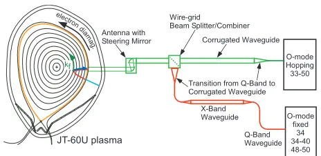
The probe wave of the frequency hopping reflectome-ter is combined with other probe waves from the fixed fre-quency O-mode reflectometers by a wire-grid beam com-biner and then launched into the plasma as shown in Fig. 2.
Fig. 2 Schematic of the millimeter-wave transmission line to-gether with the three-channels fixed-frequency O-mode reflectometer system. Two probe waves, one from each reflectometer system, are combined/split by a wire-grid beam combiner/separator. Red line in the plasma shows the result of ray tracing with a frequency of 49.5 GHz in E49534 (see Fig. 5).
Fig. 3 Characteristics of pull-in time of the synthesizer during fast frequency hopping. Upper figure shows a staircase launch frequency pattern in units of MHz for full band hopping. Lower figure shows the time evolution of the IF power with a frequency of 32 MHz.
The antennas for the incident and received waves are lo-cated atZ =0.1 m, and the injection angle of the probe wave is fixed at zero degrees (horizontal injection) in a typ-ical experiment. When the system is used as a Doppler re-flectometer, the plasma position is optimized to avoid the detection of the mirror reflection component. In the case shown in Fig. 2, only scattered waves satisfying the Bragg condition (kf = 2kiN, where kf,ki, and N are the wave
nized while maintaining a 32 MHz frequency difference. To evaluate the dead time for each stair step, the typical pull-in time of the synthesizer has been tested using an X-band mixer, a 32 MHz X-bandpass filter, and a video detec-tor. As shown in Fig. 3, the IF power was fluctuated just after frequency hopping owing to unlocking of PLL stabi-lizer. Typically, 500µs after hopping (700µs at the maxi-mum), the two oscillators can be synchronized. Based on this result, each frequency step is typically held constant for 20 ms, and 13 steps are used for typical profile mea-surements, including 1 marker step. Thus, about 250 ms is required for each sweep.
3. Experimental Results
3.1
E
rprofile measurement using Doppler
reflectometer
The principle of Doppler reflectometry and its ap-plication to thev⊥(Er) profile measurement can be found
elsewhere [13, and references therein]. A fundamental re-quirement of a Doppler reflectometer is the geometrical ar-rangement of the antenna against the cutoffdensity layer. In JT-60U, as described above, the plasma position is ad-justed so as to receive only scattered waves satisfying the Bragg condition and so that the frequency hopping reflec-tometer system acts as a Doppler reflecreflec-tometer. Because the wavenumber of density fluctuations perpendicular to the magnetic field line k⊥ is typically much larger than the other components,kandkr, in tokamak plasmas (i.e.,
k⊥ ∼ kf), the Doppler shift frequency fD of the density
fluctuation is expressed as fD =Nkiv⊥/π, wherev⊥ is the
component of the turbulence velocity perpendicular to the magnetic field line.
The initialErprofile measurements using the Doppler
reflectometer were performed in ELMy H-mode dis-charges with a plasma current (Ip) of 1.6 MA and a toroidal
magnetic field (BT) of 3.5 T. One second after the main
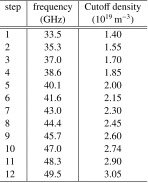
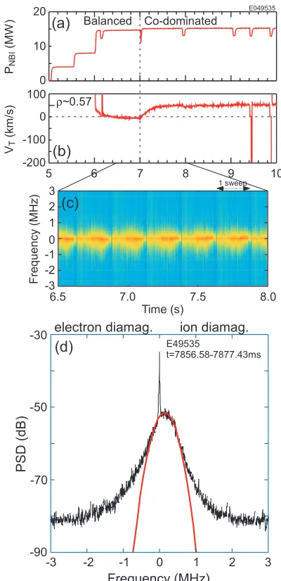
heating, the combination of tangential neutral beam in-jection (NBI) units was changed from balanced inin-jection to co- or counter-dominated injection at t = 7 s. The toroidal rotation atr/a∼0.6 increased in the co- or counter-direction as shown in Figs. 4 and 5. Here, the positive toroidal rotation means co-direction to the plasma current. In these discharges, 12 frequency-hopping steps (Ta-ble 1) were applied. The frequency change correspond-ing to each sweep can be seen in the spectrogram of den-sity fluctuations as shown in Figs. 4 (c) and 5 (c). When the toroidal rotation became faster in the counter-direction,
4 38.6 1.85
5 40.1 2.00
6 41.6 2.15
7 43.0 2.30
8 44.4 2.45
9 45.7 2.60
10 47.0 2.74
11 48.3 2.90
12 49.5 3.05
the peak frequency in the spectrogram moved in the neg-ative direction as shown in Fig. 5 (c). Figures 4 (d) and 5 (d) compare the frequency spectrum of density fluctua-tions measured with the innermost channel (at the high-est frequency of 49.5 GHz). In both cases, fD can be
determined by a fitting function, which is expressed as
αexp(−(f − fD)2/σ2). Here, αand σ are fitting coeffi
-cients. It is noted that the sign of the Doppler shift changed when the sign of the toroidal rotation changed, indicating that the sign ofv⊥changed. By applying the same analysis to each frequency step, the radial profile of fDis obtained,
as shown in Fig. 7 by using the electron density (ne) profile
shown in Fig. 6 (a).
The measuredv⊥contains two components: phase ve-locity of the density fluctuation (vphase) andE×Bvelocity
of the plasma (vE×B), i.e., v⊥ = vphase +vE×B. Because
vphasehas not been measured directly in JT-60U, the
con-dition of thevE×Bvphaseis assumed to be similar to those
of other studies [13, 14]. Then, we obtain the relationship betweenvE×B and fD as vE×B = c fD/(2f N) (where f is
the frequency of the incident wave, andcis the velocity of light). In our analysis, N and the scattering point (R
andZ) are evaluated by a ray-tracing code [15] using ac-tual plasma equilibrium and plasma profiles. Finally, Er
can be evaluated using the total magnetic field at the scat-tering region (Btotal) asEr=vE×BBtotal[8].
The symbols in Fig. 7 (b) represent the radial profile of
Erin co- and counter-rotating plasmas. At the edge region
near the top of the pedestal (r/a ∼ 0.9), negative Er
val-ues produced by the steep pressure gradient at the H-mode pedestal were observed in both the co- and counter-rotating cases. This level of negativeErhas been observed near the
top of the pedestal [16]. In the core region (r/a∼0.6), pos-itiveErwas observed in a co-rotating plasma (E49535). A
change in the sign ofEr from negative to positive across
Fig. 4 Waveforms of (a) NBI power and (b) toroidal ro-tation measured with charge exchange recombination spectroscopy when balanced NBIs are changed to co-dominated NBIs. (c) Spectrogram of density fluctua-tion measured on the Doppler reflectometer. (d) Fre-quency spectrum of density fluctuation at 49.5 GHz (nc=
3.05×10¹⁹m−3). Orange line shows the fitting line for
determining fD. Negative frequency means that density
fluctuation propagates in the electron diamagnetic drift direction.
tokamaks [8]. In the co-rotating plasma, the evaluatedEr
profile is consistent with that evaluated by the radial force balance equation assuming neoclassical poloidal rotation as shown in Fig. 7. However, the absolute value ofEr in
the counter-rotating plasma is different from that evaluated by the radial force balance equation. Because the discrep-ancy is large at the edge region, one possible reason is the different level of fast ion losses caused by different orbits of passing fast ions originating from tangential NBIs (i.e., a larger orbit loss was observed with counter-tangential NBIs). Further analysis to understand this discrepancy
re-Fig. 5 Waveforms of (a) NBI power and (b) toroidal rota-tion measured with charge exchange recombinarota-tion spec-troscopy when balanced NBIs are changed to counter-dominated NBIs. (c) Spectrogram of density fluctua-tion measured on the Doppler reflectometer. (d) Fre-quency spectrum of density fluctuation at 49.5 GHz (nc=
3.05×10¹⁹m−3). Orange line shows the fitting line for
determining fD. Negative frequency means that density
fluctuation propagates in the electron diamagnetic drift direction.
mains to be investigated as future work.
3.2
Density fluctuation measurement using
correlation reflectometer
Fig. 6 Comparison of (a) density profile and (b) toroidal rotation profile for E49534 (counter-rotation) and E49535 (co-rotation) att=7.5 s. Shaded area in (a) shows measure-ment region of the Doppler reflectometer (see. Table 1).
frequency of two fixed-frequency reflectometers. At each frequency step, the radial distance between the two reflec-tometer channels is calculated using the electron density and electron temperature profiles (the electron tempera-ture (Te) is used to correct the relativistic effect of the
cut-offcondition [17]). Then, to obtain the radial correlation length, the coherence of the two reflectometer signals is plotted as a function of the radial distance between the two reflectometers.
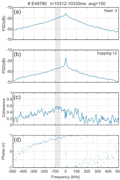
When we plot the coherence of each step, we adopt the averaged coherence of density fluctuations in a certain frequency range. In the case shown in Fig. 9, the high-est coherence was found in the frequency range of−100 to−50 kHz. The frequency range was determined using the nearest channels and then the same frequency range was applied to all frequency steps. Note that the frequency spectra shown in Figs. 9 (a) and (b) were nearly symmet-rical, in contrast to the frequency spectra of the Doppler reflectometer shown in Figs. 4 and 5, indicating that the geometrical configuration is suitable for a correlation re-flectometer.
In JT-60U, the impact of ECH on the ITB has been investigated, and ECH was found to be capable of
degrad-Fig. 7 Comparison of (a)fDprofile and (b)Erprofile for E49534
(counter-rotation) and E49535 (co-rotation). Symbols represent theErprofile evaluated on the Doppler
reflec-tometer. Lines in (b) represent theErprofile evaluated by
radial force balance equation with neoclassical poloidal rotation.
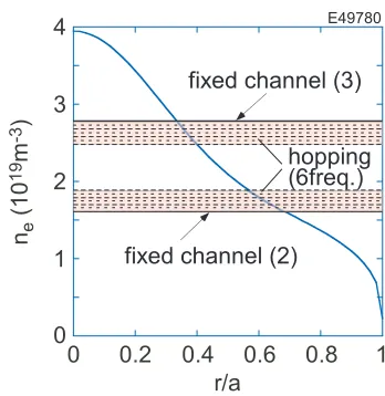
Fig. 8 Density profile and measured density region of the corre-lation reflectometer (see Table 2).
ing the ion temperature ITB (Ti-ITB) [18]. Because the
Fig. 9 Example of analysis of radial correlation. (a) and (b) Power spectral density of fixed-frequency channel and hopping channel, respectively, and (c) and (d) coherence and phase, respectively, of the two signals shown in (a) and (b). Ensemble average number was 100.
Table 2 Frequency and cutoffdensity of each step in correlation reflectometer.
step frequency Cutoffdensity (GHz) (1019m−3)
1 36.5 1.66
2 37.0 1.70
3 37.5 1.75
4 38.0 1.79
5 38.5 1.84
6 39.0 1.89
7 44.7 2.48
8 45.1 2.53
9 45.6 2.58
10 46.0 2.63
11 46.5 2.68
12 46.8 2.73
Fixed-2 36.0 1.61
Fixed-3 47.3 2.78
JT-60U weak shear plasmas withTi-ITB [19]. Considering
the density profile near the measured points of two fixed-frequency reflectometers, the fixed-frequency at each of the 12
steps is carefully determined as summarized in Table 2. In a weak shear plasma withIp = 1.2 MA and BT =
3.7 T (E49780), the centralTidecreased during the
appli-cation of central ECH (the absorption loappli-cation wasr/a <
0.3) as shown in Fig. 10. Immediately after the injection of ECH, the centralTe started to increase together with
the reduction ofne. About 100 ms later, the centralTi
de-creased together with the change in the density fluctuation as shown in Fig. 10 (e). Figure 10 (g) compares the coher-ence of density fluctuations with and without ECH, indicat-ing that the long-range correlation (>∼2 cm) increased. In this discharge, the density profile changed so that the den-sity gradient near the measured location became smaller. However, the change in the characteristics of the density fluctuations was not correlated with the change in the den-sity profile but with the degradation ofTi-ITB.
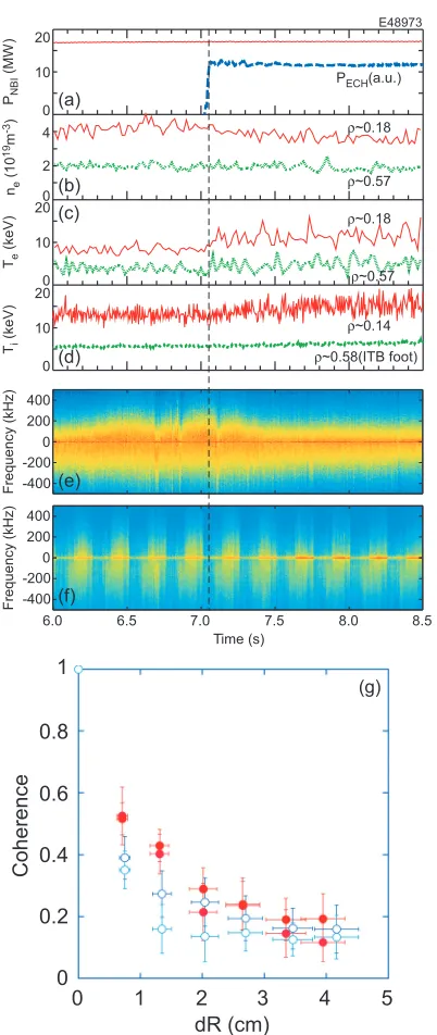
To understand the relationship between the changes in the density profile and radial correlation, the correlation reflectometer was applied to another weak shear plasma withIp =1.5 MA andBT =3.7 T (E48973), whereTi-ITB
was maintained during the application of central ECH. As shown in Fig. 11, the centralTi andTe were constant or
increased slightly after ECH injection, whereas the cen-tral ne gradually decreased; as a result, the density
gra-dient near the measured location decreased. As the den-sity profile changed, the shape of the frequency spectrum measured with the fixed-frequency reflectometer, shown in Fig. 11 (e), peaked gradually during ECH. This type of gradual change in the shape of the frequency spectrum was also observed in theTi-ITB degradation case shown in
Fig. 10 (e). However, the radial correlation of the density fluctuations was almost constant. These experimental ob-servations indicate that the observed change in the radial correlation is caused not by the change in the density pro-file but by the change in the characteristics of the density fluctuations.
4. Summary
A frequency hopping reflectometer using a synchro-nized synthesizer has been developed for use as a Doppler reflectometer and correlation reflectometer in JT-60U. The synchronized synthesizer provides a fast sweep of the fre-quency of the probe wave so that 13 varied frefre-quency steps can be typically applied every 250 ms. The system has been applied to density fluctuation measurements to eval-uate theErprofile or the radial correlation of density
Fig. 10 Typical example ofTi-ITB degradation case. Waveforms
of (a) NBI and ECH power, (b) electron density, (c) elec-tron temperature, and (d) ion temperature. (e) Spec-trogram of density fluctuation measured on the fixed-frequency reflectometer (47.3 GHz). (f) Spectrogram of density fluctuation measured on the frequency hopping reflectometer. (g) Coherence of density fluctuations at r/a ∼0.3. Open and closed symbols denote data with and without ECH, respectively. Coherence is averaged in a frequency range of−100 to−50 kHz.
owing to central heating by ECH. Further analysis un-der various experimental conditions will provide useful in-formation regarding the relationship among the anomalous transport,E×Bshear, and density fluctuations.
Fig. 11 Typical example of unchangedTi-ITB case. Waveforms
of (a) NBI and ECH power, (b) electron density, (c) elec-tron temperature, and (d) ion temperature. (e) Spec-trogram of density fluctuation measured on the fixed-frequency reflectometer (47.3 GHz). (f) Spectrogram of density fluctuation measured on the frequency hopping reflectometer. (g) Coherence of density fluctuations at r/a ∼ 0.3. Open and closed symbols denote data with and without ECH, respectively. Coherence is averaged in a frequency range of−100 to−50 kHz.
Acknowledgments
Young Scientists (A) 18686076, Japan Society for the Pro-motion of Science.
[1] Y. Sakamoto, T. Suzuki, S. Ideet al., Nucl. Fusion44, 876 (2004).
[2] H. Takenaga, S. Higashijima, N. Oyamaet al., Nucl. Fusion
43, 1235 (2003).
[3] H. Shirai, M. Kikuchi, T. Takizukaet al., Nucl. Fusion39, 1713 (1999).
[4] K. Shinohara, R. Nazikian, T. Fujita and R. Yoshino, Rev. Sci. Instrum.70, 4246 (1999).
[5] N. Oyama and K. Shinohara, Rev. Sci. Instrum.73, 1169 (2002).
[6] N. Oyama, L.G. Bruskin, H. Takenagaet al., Plasma Phys. Control. Fusion46, A355 (2004).
[7] R. Nazikian, K. Shinohara, G.J. Krameret al., Phys. Rev. Lett.94, 135002 (2005).
[8] K. Ida, Plasma Phys. Control. Fusion40, 1429 (1998). [9] R.E. Bell and E.J. Synakowski, AIP Conference
Proceed-ings547, 39 (2000).
[10] T. Estrada, E. Blanco, L. Cupido, M.E. Manso and J. Sánchez, Nucl. Fusion46, S792 (2006).
[11] S. Graca, G.D. Conway, P. Lauberet al., Plasma Phys. Con-trol. Fusion49, 1849 (2007).
[12] T. Tokuzawa, A. Ejiri and K. Kawahata, Rev. Sci. Instrum.
81, 10D906 (2010).
[13] G.D. Conway, J. Schirmer, S. Klengeet al., Plasma Phys. Control. Fusion46, 951 (2004).
[14] M. Hirsch, E. Holzhauer, J. Baldzuhn, B. Kurzan and B. Scott, Plasma Phys. Control. Fusion43, 1641 (2001). [15] K. Hamamatsu and A. Fukuyama, Plasma Phys. Control.
Fusion42, 1309 (2000).
[16] K. Kamiya, K. Ida, Y. Sakamotoet al., Phys. Rev. Lett.105, 045004 (2010).
[17] E. Mazzucato, Phys. Fluids B4, 3460 (1992).
[18] S. Ide, H. Takenaga, A. Isayamaet al., Nucl. Fusion47, 1499 (2007).