EFFICIENT COMMUNICATION FOR MOBILE DEVICES IN THE
NEW ERA
A Dissertation Presented
by
YING MAO
Submitted to the Office of Graduate Studies, University of Massachusetts Boston in partial fulfillment
of the requirements for the degree of
DOCTOR OF PHILOSOPHY
May 2016
CHAPTER 1
ABSTRACT
EFFICIENT COMMUNICATION FOR MOBILE DEVICES IN THE
NEW ERA
MAY 2016
YING MAO
Ph.D., UNIVERSITY OF MASSACHUSETTS BOSTON
Directed by: Professor Bo Sheng
Smartphone has become one of the most revolutionary devices in the history of computing. With various kinds of applications, the scope of smartphone has been significantly broadened in the past few years including almost every aspect in our daily life. However, due to the limited on-board resources such as CPU, storage, network bandwidth and battery power, smartphones and the mobile network serving them bring new challenges that have not been encountered in the traditional computing and networking environments.
This dissertation focuses on the research areas of improving the network architec-ture and enhancing the current applications on smartphones. It mainly investigates the areas in the following two directions for three representative categories of mobile services.
• In the first direction, the dissertation aims to develop new communication mod-els for smartphone Ad-Hoc networks to achieve efficient communication in the proximity. It is motivated by the fact that smartphone Ad-Hoc networks can help improve the current location-based services and propel new applica-tions. Moreover, the new communication models provide complementary alter-natives to the traditional infrastructure-based wireless networks.
a cloud-assisted approach to provide a set of advanced file operations, such as encryption, decryption and compression, on smartphones. Furthermore, by uti-lizing the on-board Near Field Communication(NFC) module, we develop an algorithm to securely share the files between mobile devices. For the services of real-time video streaming, we propose approaches that identify a user’s status by analyzing the accelerometer data and then, dynamically adjust the buffer mechanism to save network bandwidth on smartphones.
CHAPTER 2
INTRODUCTION
With recent advances, smartphones have become one of the most revolutionary
devices nowadays. According to a report from Pew Research Center in 2015, about
64% of U.S. consumers own a smartphone and 39% of the total Internet traffic is
consumed by mobile devices. Consequently, a variety of applications have been
de-veloped to meet users’ demands in all aspects. Today’s smartphones have gone far
beyond a mobile telephone as they have seamlessly dissolved in people’s daily life in
all perspectives by providing all kinds of services through mobile devices.
Among the various services on mobile devices, this dissertation studies three
pop-ular and representative categories, (1) Location-based services; (2) Cloud-storage
services; (3) Real-time video streaming services.
2.1
Research Problems and Challenges
In this section, we identify the research problems and challenges for each of the
three representative mobile service categories.
2.1.1 Location-based Services
Location-based services for mobile devices have attracted a large volume of users [1–
6]. The current location-based services, however, are still built upon the client-server
architecture which incurs some unavoidable issues. Let us consider an example where
a department store in a mall tries to deliver a flyer file to a nearby shopper. In the
its server; (2) the user has to install the store’s applications; (3) the user connects to
the Internet in the mall and reports his location to the store’s server; (4) the server
delivers the flyer file to the user. This process involves a few representative drawbacks
that an Ad-Hoc network can help address. First, a user cannot discover nearby data
or information (step 2). He has to register for each and every service he is
inter-ested in. With an Ad-Hoc network, the user can browse or receive all the unknown
services nearby as long as they transfer information on a common channel (such as
WiFi). Second, step 3 and step 4 require the Internet connection which may not be
always available, e.g., subway stations, crowded and congested areas, and the areas
with infrastructure failures. Not to mention that when the store and user are close
to each other, the data transfer going through the Internet may not be necessary and
could incur additional costs to the user. Third, step 3 requires an accurate indoor
localization scheme.
After investigating the problems of current client-server architecture, we argue
that Ad-Hoc network model is a complementary alternative that can effectively help
solve all the above issues. With an Ad-Hoc network, be able to hear the signals from
the store is a best evidence that the user is close to the store. Therefore, constructing
a mobile Ad-Hoc network (MANET) with hop-by-hop communication to carry local
data traffic is desirable in practice.
However, the current routing protocols used in MANETs suffer from two major
problems. First, it is costly and inefficient to establish a path from the source to
destination. Traditional MANET routing protocols either pay a high cost for
main-taining routing tables or flood a request message in the entire network for on-demand
path discovery. Both categories require a large number of messages to be delivered
for establishing a path. The second problem resides in the path recovery protocol
which is usually triggered by an observed failure and proceeded by repeating the
2.1.2 Cloud-storage Services
The cloud related services has been widely deployed in many applications, such
as edge computing [7–9], deep learning [10–12], big data processing [13–15], resource
management [16,17]. In this field, we consider the mobile application of cloud-storage
service, which is a recent emerging technology for mobile devices. Representative
products include iCloud [18], Dropbox [19], Box.com [20], Google Drive [21], and
etc. [22, 23]. Basically, each user holds a certain remote storage space in cloud and
can access the files from different devices through the Internet. Synchronization and
file consistence are guaranteed in these cloud-storage services. When smartphones
become popular, it is ineluctable for users to couple cloud storage service with their
smartphones. However, users and developers have encountered specific challenges
due to the limitations of smartphones. First, the storage capacity of a smartphone is
limited compared to regular desktops and laptops. Second, the network bandwidth
of the cellular network is limited. At this point, major U.S. mobile networks carriers
rarely provide unlimited data plans and the service scalability is limited by
funda-mental constraints. Finally, energy consumption is a critical issue for smartphone
users.
With the above constraints in mind, most existing smartphone applications for
cloud-storage service follow one important design principle of not keeping local copies
of the files stored in cloud because smartphones may not have sufficient space to hold
all the files, and downloading those files consumes a lot of bandwidth and battery
power. Instead, only meta data is kept on smartphones by default. Though this
design is efficient, it limits the capabilities of the applications. Some file operations
that can be easily done with local copies become extremely hard, if not impossible,
2.1.3 Real-time Video Streaming Services
Streaming video is another popular service for smartphone users. Most of the
popular stream video providers such as Youtube, Netflix, and Hulu have developed
mobile applications to serve their clients. However, designing mobile applications
for video streaming faces new challenges that do not exist in traditional wired
In-ternet. One of the most critical issues is the network connection. Compared to the
wired network users, a mobile user’s network bandwidth is much limited. All the
common connections for mobile users such as WiFi, 3G, and 4G have significantly
lower throughput and the link qualities are heavily affected by environmental factors
such as obstacles and distance to infrastructure nodes. In addition, user mobility is
another unique feature for mobile users. When a user is mobile, the wireless link
qual-ity could be highly dynamic and a user can be temporarily disconnected in a certain
region. Along with the movement, a user could also trigger the handoff protocol to
switch the associated infrastructure node. All these dynamics in a wireless network
serving mobile users make the design of streaming video mobile applications more
challenging. Video streaming is a real-time service and extremely sensitive to the
change of network conditions. Any network jitter or delay could pause the playback
of the video clip. In addition, network cost is another issue that should be considered
when developing a mobile app for streaming videos. On one hand, end-users may
want to consume bandwidth as little as possible when watching the video because the
video delivery may incur a cost, e.g., 3G or 4G, and additional energy consumption.
On the other hand, more importantly, the service providers may want to save the
network bandwidth cost while serving the end-users.
A rule of thumb to achieve is to deliver only the necessary video data to the users.
With mobile users, it is more feasible to manage to achieve this goal because the
mobile streaming video applications are usually developed by the service providers.
a general web browser, mobile streaming applications enable the service providers
with more flexible functions to manage the data delivery from the source server to
the end users. However, how to identify the changes of link quality and to predict
the trend the changes of a mobile user remains a challenge.
2.2
Dissertation Contributions
To address the above research problems, this dissertation designs, develops and
evaluates several novel communication models and enhanced applications. In the rest
of this section, we briefly discuss the each of the three representative mobile service
categories and summarize the contributions in each field.
Location-based services: In this field, our objective is to use MANETs to
provide an alternative network architecture to the infrastructure-based client-server
communication model. With this target in mind, we make the following contributions
in this dissertation.
(1) We propose long-range radio assisted communication model(LAAR [24, 25]) for
regular data transmission where a long-range, low cost, and low rate radio is
integrated into smartphones to assist regular radio interfaces such as WiFi and
Bluetooth. LAAR uses the long-range radio to carry out small management data
packets to improve the routing protocols. Specifically, we develop new schemes
to improve the efficiency of the path establishment and path recovery process in
the on-demand Ad-Hoc routing protocols.
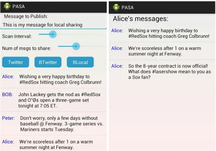
(2) For local message dissemination, we build a system upon a new
communica-tion model, called passive broadcast (PASA [26]). It is a connectionless and
receiver-initialized model where each node periodically scans other nodes in the
communication range and obtains their data if available. The representative
a mandatary ‘peer discovery’ function to fetch basic information about nearby
devices. This function can be easily extended to implement passive broadcast
mechanism without modifying the existing network protocol stack.
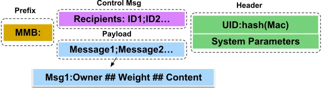
(3) Based on PASA, we build a Mobile Message Board (MMB[27]), a location-based
service for smartphone users to post and share messages in a certain area. Our
algorithm design focuses on the message management on each phone considering
its own schedule of turning the wireless device on and off. We present algorithms
for two different cases to maximize the availability of the messages.
(4) We implement and evaluate our solutions on the Android smartphone testbed
through small scale experiments. Furthermore, we collect the results from
sim-ulations for large scale settings to validate the scalability of our proposed
ap-proaches.
Cloud-storage services: Our basic idea to enhance cloud-storage services is
to launch a cloud instance to assist users to accomplish advanced file operations.
By using the resources of the instance, smartphone users will significantly reduce
the bandwidth consumption for file operations. To implement this idea, we develop
Skyfiles [28] system for smartphone users to manage their files in cloud storage with
more capabilities. The main contributions of Skyfiles lie as follows.
(1) It extends the available file operations for mobile devices to a more enriched set
of operations including downloading, compressing, encrypting, and converting
operations.
(2) It includes a protocol for two smartphone users to transfer files from one’s cloud
storage space to the other’s cloud storage.
(3) It includes secure solutions for all the above operations to use shared cloud
Real-time video streaming services: In this category, we target on improving
video prefetch/buffer mechanism that is commonly used in video streaming services.
We develop an efficient and dynamic video buffer control scheme named (DAB [29])
that tries to keep a smooth playback with minimum data delivered to the user by
adjusting the buffer size. DAB contains the following contributions.
(1) It takes the mobility of smartphone users into consideration and combines the
signal strength as well as accelerometer measurements to dynamically adjust the
buffer size.
(2) It is implemented on Android smartphones to play Youtube videos and evaluated
with real users’ mobility traces.
2.3
Dissertation Organization
The rest of this dissertation is organized as follows. In Chapter 2 and 3, we
in-vestigate two new efficient Ad-Hoc communication models for smartphones as well as
a suite of new techniques to significantly improve the efficiency. Both models target
on reducing the cost of route establishment and maintenance, while one model is
for bulk data communication and the other model is for short message dissemination.
Specifically, we presentLAARfor bulk data communication in Chapter 2 and discuss
the details in protocol design, system implementation and performance evaluation.
Chapter 3 presentsPASA for short message dissemination and discusses the system
model, problem formulation, parameter optimization and performance evaluation. In
Chapter 4, we proposeMMBsystem for nearby smartphone users to share messages
with each other based on PASA communication model. MMB provides an
alterna-tive to traditional infrastructure-based client-server architecture for location-based
services. Skyfiles is proposed in Chapter 5 to improve the cloud-storage services by
utilizing a cloud instance. Chapter 6 is our work of DABthat enhances the real-time
CHAPTER 3
LONG-RANGE RADIO ASSISTED AD-HOC NETWORKS
In this chapter, we study smartphone-based Ad-Hoc networks to support
applica-tions that require interacapplica-tions and communicaapplica-tions in the proximity. It is motivated
by the fact that location plays an extremely important role in mobile applications.
With an Ad-Hoc network, hearing the signals from the other users or service providers
is the best evidence that the user is close to the each other. Therefore, constructing
a mobile Ad-Hoc network (MANET) with hop-by-hop communication to carry local
data traffic is desirable in practice. However, the current routing protocols used in
MANETs suffer from two major problems. First, it is costly and inefficient to
estab-lish a path from the source to destination. Traditional MANET routing protocols
either pay a high cost for maintaining routing tables or flood a request message in
the entire network for on-demand path discovery. Both categories require a large
number of messages to be delivered for establishing a path. The second problem
resides in the path recovery protocol which is usually triggered by an observed failure
and proceeds by repeating the path establishment process. In practice, however, this
recovery process is slow. routingtable
To address the problems, we investigate a new long-range radio assisted Ad-Hoc
communication model for smartphones as well as a suite of new techniques to
sig-nificantly improve the performance of path establishment and recovery. We have
prototyped this model on commercial Android phones by integrating additional
as a tradeoff, its data rate is low (tens of bps) unsuitable for bulk data transmission.
We propose to use this additional radio channel for control and management messages
while data communication is still carried by WiFi or Bluetooth.
Long-range Radio
WiFi / Bluetooth WiFi / Bluetooth WiFi / Bluetooth
Source Destination
Figure 3.1: Long-range Radio Assisted Model
3.1
Related Work
Generally, there are two types of routing protocols in MANETs. One type is
proac-tive protocols such as DSDV [31], OSLR [32]. In these protocols, each node maintains
one or more tables with routing information to every other node in the network. The
other type is demand protocol (reactive), such as DSR [33], AODV [34]. In
on-demand protocols, the routes are created as required. In this chapter, we mainly
focus on the on-demand routing protocol design.
A lot of innovative approaches in this area have been studied to improve the
network performance from different aspects. For example, in LQSR [35], the route is
selected based on link quality metrics, such as expected transmission count (ETX),
per-hop RTT, and per-hop packet pair. However, LQSR only works with static setting
and fails to deal with topology changes. Frey et al. [36] focus on geographic routing
to overcome topology changes with mobility. Another important aspect is to utilize
multiple resources on one node to achieve better performance. For example, [37]
attempts to use multi-channel on one node and proposes a hybrid channel assignment
strategy. Multiple resources on one device make the routing protocols more flexible.
is equipped with multiple radio interfaces. MR-LQSR uses a new metric named
weighted cumulative expected transmission time(WCETT) to provide better route
selection. The AODV-MR uses the multi-radio interfaces communication to improve
spectrum utilization and reduce interference. Extended-DSR attempts to address
limited capacity and poor scalability problem by taking advantage of multi-radio
feature.
Our work is closely related to [26, 38–42]. However, in their settings, each node
is equipped with multiple 802.11 wireless cards. And they focus on addressing issues
of interference and channel allocation. In our case, the two interfaces work on
dif-ferent frequencies. We mainly focus on utilizing the collaborations of these radios to
boost the network performance. In our previous work [24], we investigate the route
construction and as a following work, we design the whole protocol.
3.2
Background and Problem
We target on the routing problem in a MANET where a source node aims to
transfer data to a destination node. Each node in our setting is a smartphone and
the phone-to-phone Ad-Hoc communication is carried out by WiFi or Bluetooth
in-terface. We adopt on-demand Ad-Hoc routing protocols such as DSR and AODV,
where each node does not maintain stateful link information and a path is established
only when the source intends to transfer data to the destination. Compared to
proac-tice protocols, on-demand routing protocols are more suitable in a dynamic network
considering user mobility. Here we introduce the details of some key components in
the traditional on-demand Ad-Hoc routing protocols and list their drawbacks which
motivate our new design.
Path Establishment: Establishing a path from the source to destination is a
basic and important step in Ad-Hoc routing. The basic design in the prior work is
one of them reaches the destination. Then the destination will send a route replay
message(RREP) to the source tracing back the transmission path of the RREQ. Once
the RREP is received by the source, a routing path is successfully established. This
flooding-based scheme, however, is costly in two aspects. First, the RREQ message is
broadcast by a node to all its neighbors in omni-direction. Most of the messages will
never reach the destination. Although RREQ message is often confined with a
time-to-live (TTL) parameter, it still causes a large number of useless messages transferred
which consume energy of each node and yield wireless signal interferences in the
MANET. In addition, the exchange of RREQ and RREP takes a round-trip time
with hop-by-hop delivery. Considering the interference and processing time at each
relay node, this initial delay could degrade the throughput performance especially
when transferring small amounts of data.
Path Cache: Path cache is often included in the MANET routing protocols to
avoid unnecessary path establishments. Each node stores the paths from itself to
other nodes into a route cache based on the RREQs or RREPs it overhears. In the
path establishment, when an RREQ arrives, the node will first check its route cache.
If there exists a path to the destination in the route cache, the node will reply to
the source without propagating the RREQ. In this scheme, the validity of the cached
paths is crucial to the performance. Because of the node mobility, the cached paths
may not be available when the node intends to use them. In the traditional routing
protocols, the validity of the cached paths is never checked. When a node attempts to
use a cached path and later finds the path is stale, the source will have to re-establish
another path.
Path Recovery: Path recovery is another important component in MANET
routing protocols. When a node on the path moves out of the transmission range of
its neighboring hops, a link is broken and the path recovery protocol will be triggered
to receive a link layer acknowledge detects the broken link and sends a route error
message(RERR) back to the source. The source will first search its route cache for an
alternative route to the destination. If no alternative is found, the source initializes a
new path establishment process. In addition, any node that receives or overheads an
RERR message will delete all the routes in the cache that contain the broken link.
Path recovery inherits the issues we have mentioned for path establishment and path
cache.
Our Problem Setting: In this chapter, we aim to develop an efficient MANET
routing protocol based on the integration of a long-range radio interface that helps
address the above issues. Specifically, we consider a MANET consisting of smartphone
nodes and each smartphone is equipped with two heterogeneous wireless interfaces:
one is the regular wireless radios such as WiFi and Bluetooth, and the other is a new
long-range radio. According to our prototype, the long-range radio has a much longer
communication range (up to miles) than WiFi or Bluetooth. Its power consumption
is extremely low which is suitable for smartphones. However, the network bandwidth
of the long-range radio is significantly lower than the regular radios. More details of
the hardware characteristics will be introduced in Section 3.4. In our solution, the
long-range radio will be used to broadcast small management packets while the data
transfer is still carried by the regular radios in a hop-by-hop fashion. In addition,
considering the coverage of the long-range radio, this chapter targets at the local
data transfer where the source and destination can directly reach each other over the
long-range radio. Our goal in this chapter is to use the new long-range radio assisted
communication model to improve the performance of MANET routing protocols.
Specifically, with the new long-range radio interface, we aim to reduce the message
flooded in the entire network, decrease the time overhead of establishing or recovering
3.3
System Design of LAAR
In this section, we present our solution LAAR which mainly consists of an efficient
path establishment protocol and path recovery protocol. In addition, we develop
a new route cache management scheme that serves both path establishment and
recovery protocols.
3.3.1 Path Establishment
In this subsection, we discuss the motivations and technical details of path
estab-lishment in LAAR system.
3.3.1.1 Motivations
Our design of the path establishment process includes the following two major
new techniques.
Bi-directional Route Request Flooding: Traditionally, the route request
message (RREQ) is flooded from the source towards the destination. In our problem
setting, the source and destination are directly connected over the long-range radio.
Thus, before flooding the RREQ message, the source can use the long-range radio
to notify the destination about the upcoming communication session. An then, the
destination will participate in this process as well. In out solution, therefore, both the
source and destination flood the RREQ message towards each other. When a node
receives both request messages implying a path has been established, it can send an
announcement message through its long-range radio.
RSSI-guided Flooding: Traditionally, the RREQ messages are forwarded to
all directions and most of them are wasted. In our solution, we confine the region
involved in the flooding process by considering the received signal strength (RSSI)
of the packets sent over the long-range radio. The basic intuition is that for any
communication session, only the nodes “between” the source and destination should
away from the destination than the source, it should not forward the RREQ for
the session. Our solution provides relevant RSSI information to each node to help
determine if the node should participate in the flooding process.
3.3.1.2 Complete Path Establishment Protocol:
Our path establishment protocol includes three phases. In the first phase, we
develop a newthree-way handshake protocolto enable the bi-directional route request
flooding and prepare for aRSSI-guided flooding. In the second phase, the source and
destination each broadcasts an RREQ and all the participating nodes propagate the
RREQs as in the traditional routing protocols. The third phase is for announcing an
established path. We assume that each node maintains a regular routing table that
hosts the routing information for all the active communication session it participates.
The routing table contains at least three columns: the source node ID (SRC), the
destination node ID (DST), and an ordered list of node IDs that represent the path
to the destination (PATH TO DST). After a path is successfully created, each node
in the path will add a new entry in its routing table for this session.
In our solution, each node keeps an additional table, called preparation table,
to help decide whether the node will participate in a path establishment process.
The structure of a preparation table is illustrated in Fig. 3.2. Compared to the
routing table, each entry in the preparation table includes some more fields such as
PATH TO SRC and four RSSI values.
RSD RSSI of a packet from the source measured at the destination
RDS RSSI of a packet from the destination measured at the source
RS RSSI of a packet from the source measured at this node
RD RSSI of a packet from the destination measured at this node
SRC DST RSSIs PATH_TO_SRC PATH_TO_DST
Next, we present the details of the three phases where the preparation tables
will assist to eventually update the routing tables on the path from the source to
destination.
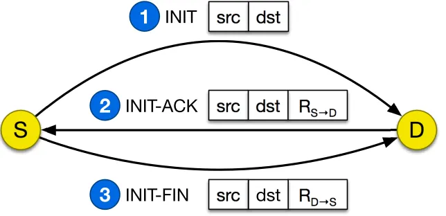
Phase I - Three-way handshake: Assume the source S tries to send data to the destination D and they are within each other’s communication range over the long-range radio. S first sends out an INIT message including S and D’s IDs via the long-range radio. The combination of the source and destination’s IDs < S, D >
uniquely identifies a communication session. Once receiving the message, D sends an INIT-ACK message back to S. Besides the source and destination’s IDs, this message also includes the RSSI of the INIT message indicated by RS→D. Finally, S sends the last handshake message INIT-FIN including the RSSI of the INIT-ACK
message (RD→S). The structures of these three messages are illustrated in Fig. 3.3.
INIT-FIN
3
R
D→S
S
D
INIT
src
1
dst
INIT-ACK
2
R
S→D
src
dst
src
dst
Figure 3.3: Three-way handshake protocol
When overhearing the three-way handshake messages, every node that is neither
source or destination applies the following Algorithm 1. Basically, the preparation
ta-ble hold the candidate sessions that may be added into the routing tata-ble later. When
a node receives an INIT message (lines 3–4), it adds a new entry into the preparation
table recording the new session as well as the RSSI of this message (RS). INIT-ACK
process at the source and destination, and also help enforce the RSSI-guided
flood-ing. When receiving an INIT-ACK message (lines 5–11), the node first searches its
preparation table for the matching session with <src, dst>. If a matching entry E is found, the node will compare the recorded RS value with the RSSI value (RS→D) in the INIT-ACK message. This entry E will be removed from the preparation table if
E.RS< β·RS→D where β ∈(0,1) is a threshold depending on the signal prorogation model. This step filters out the nodes that are further away from the source node
than the destination. If E.RS≥β·RS→D, the node will update the entry E by setting E.RD value to be the RSSI of this INIT-ACK message. Similar steps are applied
when processing an INIT-FIN message (lines 12–18).
Algorithm 1 Process Three-way Handshake Messages 1: function Receive(msg):
2: Read msg.src, msg.dst, and measure the RSSI of the message indicated as msg.rssi
3: if msg is an INITmessage then
4: Add a new entry {SRC=msg.src, DST=msg.dst, RS=msg.rssi} into the preparation table
5: else if msg is an INIT-ACK message then
6: Search the session <msg.src, msg.dst>in the preparation table
7: if there exists an entry E for the sessionthen 8: if E.RS< β·msg.RS→D then
9: Remove this entry E from the preparation table
10: else
11: E.RSD=msg.RS→D and E.RD=msg.rssi 12: else if msg is an INIT-FIN message then
13: Search the session <msg.src, msg.dst>in the preparation table
14: if there exists an entry E for the sessionthen
15: if E.RSD value is null or E.RD< β·msg.RD→S then 16: Remove this entry E from the preparation table
17: else
18: Update the entry by setting E.RDS=msg.RD→S
Phase II - Bi-directional RREQ Flooding: In phase II, both the source and
destination will start flooding an RREQ message towards each other. Essentially,
a node will participate in flooding an RREQ only if its preparation table contains
an entry for the session of the received RREQ. In our solution, an RREQ message
path), and an additional field indicating the origin of the message, i.e., from the source
node or destination node. The following Fig. 3.4 illustrates the message structure.
Having received an RREQ, each node applies the following Algorithm 2. First, it
RREQ src dst TTL path dir 0: from the source
1: from the destination
A list of node IDs
Figure 3.4: RREQ message format
searches its preparation table for the session this RREQ represents. If there exists
an entry for the session, the node will add its own ID in the field of the path and
further broadcast the RREQ if the TTL is not expired. Meanwhile, the node will add
the path included in the RREQ into either E.PATH TO SRC or E.PATH TO DST
according to the origin of the RREQ. If the node finds that both E.PATH TO SRC
and E.PATH TO DST have been filled, it will move to Phase III to announce the
established path.
Algorithm 2 Process RREQ Messages 1: function Receive(msg):
2: Read msg.src and msg.dst, and search the preparation table 3: if there exists an entry E for the session then
4: if msg.dir indicates msg is from the source then
5: if E.PATH TO SRC = null then
6: E.PATH TO SRC = msg.path
7: else
8: if E.PATH TO DST = null then
9: E.PATH TO DST = msg.path
10: if E.PATH TO SRC and E.PATH TO DST are defined then
11: SendAnnouncement(E)
12: else if msg.TTL>0 then
13: Broadcast a new RREQ {msg.src, msg.dst, msg.TTL-1, msg.path+NodeID, msg.dir}
Phase III: Path Announcement Once a node receives the RREQ messages
(ANNO) via the long-range radio with a complete path from the source to
destina-tion. An ANNO message contains only three fields: the source (src), the destination
(dst), and the full path from the source to destination. After receiving the ANNO
message, every node will no longer forward the RREQ message for this session (by
removing the entry for the session in the preparation table). In addition, each node
checks the path and adds the session to its routing table if it is listed in the path.
Figure 3.5: Traditional Path Establishment (TTL=4)
Fig. 3.5 and Fig. 3.6 show a comparison between traditional path discovery and
our long-range radio assisted path discovery. The two orange nodes are sender S and receiverD. Fig. 3.5 shows the request message flooding with TTL (time to live) set to 4. The shortest path from sender to receiver is 3-hop long and in this partial topology,
! "
14 nodes broadcast the request when it reaches the receiver. Fig 3.6 illustrates the
benefits of bi-directional flooding and RSSI filtering. In this example, the request is
propagated from both sender and receiver and the path is established in the second
round of broadcast, i.e., when node A and B broadcast their received requests. With
the handshake messages including RSSI information, we assume the dotted circle and
arc centered at the receiver define the region where the RSSI of the receiver’s packets
is similar, i.e., RD→S. Assume the nodes on the left side of the dotted arc have RSSIs (RD) smaller thanβ·RD→S. Thus they will node forward the RREQ message. Only 7 nodes broadcast the RREQ message in Fig 3.6 when the path is established.
3.3.2 Path Recovery
Path recovery is a critical component in MANETs because of the dynamic network
topology caused by user mobility. We develop an efficient path recovery protocol in
LAAR with the following two new techniques. Due to the page limit, we omit the
detailed pseudo codes for the protocols.
Partial Path Recovery: In the prior work, once a node detects a broken link,
the notification will be sent back to the source by an RERR message, and then the
source will launch a new path establishment process. Therefore, any single link failure
will lead to a complete path establishment process which is not efficient in practice,
especially if the broken link is shared by multiple active sessions. An example is
shown in Fig. 3.7. In the traditional MANET routing protocols, while node V moves
away causing a broken link, node U will send three RERRs to the sources which will
further start three path establishment processes.
In our partial path recovery solution, the node who detects the failure will notify
the sources with a single RERR over the long-range radio and start path establishment
processes with the destinations. Referring to the example in Fig. 3.7, node U will
sources about the recovered paths over the long-range radio. Meanwhile, each source
node also sets a timer once receiving an RERR. If the detecting node cannot recover
the path to the destinations before the timers expire, the sources will initialize the
path establishment process with the destinations.
S2 S1
S3
D1
V
U V
RERR U
1 V
Path Establishment
2
D2
Path Establishment
3 Data packet
Path recovery packet
Figure 3.7: An example of partial recovery: 3 active sessions (S1,D1), (S2,D2), and (S3,D2) share a link U→V. Node V moves away and the link U→V is broken.
Proactive Path Recovery: The other new technique we develop is to
proac-tively start path recovery protocol before any link is broken. The basic idea is to
detect weak or about-to-break links based on each phone’s mobility. Considering
smartphones being the mobile nodes in our setting, we particularly use the
accelerom-eter and RSSI measurements to daccelerom-etermine if a node is moving away from a path it
belongs to. If a node detects high movements or poor RSSIs from its neighbors, it
will notify the neighboring nodes about the possible departure. Then a path recovery
process will start when the node still carries out the data transfer. Once a new path
is established, the neighboring nodes will update their routing tables to bypass the
departing node.
In practice, both accelerometer and RSSI readings are dynamic, and may not
ac-curately reflect the user movements. We develop a heuristic algorithm that combines
Algo-Algorithm 3 Proactive Path Recovery
1: RL: avg RSSI level, SL: avg speed level, C= 0 2: When a new packet is received, update R
3: if RL isGOOD then
4: C = 0; return;
5: else if RL is POOR then
6: C = 0; Start the recovery process; 7: else
8: Measure the user’s moving speed SL
9: C =
C+ ∆H : if SLis HIGH
C+ ∆M : if SLis MEDIUM
C+ ∆L : if SLis LOW 10: if C ≥τ then
11: C = 0; Start the recovery process;
rithm 3 illustrates the detailed process when a packet arrives. Specifically, we define
three discrete levels for RSSI values, {GOOD, FAIR, POOR}. While a GOODRSSI
indicates a stable link, a POOR RSSI will trigger a path recovery process. When a
FAIR RSSI is received, our solution will start to periodically measure the
accelerom-eter. Our intuition is that a highly mobile user with FAIR RSSIs is likely to cause a
broken link. Similar to RSSI measurements, we use three levels, {HIGH, MEDIUM,
LOW}, represent a user’s moving speed. Our algorithm use a variable C to track the user speed accumulation. According to the speed level, we increase C with heuristic values (line 9, ∆H >∆M >∆L). When C exceeds a threshold τ, the path recovery process will be started.
3.3.3 Route Cache Management
In MANET routing protocols, every node records the known paths in a route
cache to avoid the delay of path establishment. For both path establishment and
path recovery protocols, route cache plays an important role. When processing an
RREQ message, a node will first check its route cache and if a matching path to the
destination is found, the node will reply to the source without further flooding the
to adopt them. In a MANET, the link conditions are dynamic and the known paths
may not be stable. Using stale paths will cause path recovery once a broken link is
detected and yield a worse performance than not using the route cache.
In our solution, we address this issue by removing invalid paths in the cache based
on the overheard packets. Two types of packets will trigger a cleansing of the route
cache. First, if a node receives a broadcast RERR packet over the long-range radio
indicating a broken or about-to-break link, it will search its route cache and eliminate
all the paths that contain the link specified in the RERR. Second, every node will
listen to the active data transmissions over WiFi or Bluetooth from the neighboring
nodes even if the packets are not designated to it. By sniffing these packets (e.g.,
from node j to node k), nodeican measure the RSSI and estimate the quality of the link j →i. If the RSSI is in the category POOR, node i will remove all the paths in its cache that contain the link j →i.
Complete Protocol in Path Recovery: Here is the complete protocol. When
the recovery process is initialized by nodei, it first checks its path cache to see if there is another route to the destination. If an alternative route is found, node i sends a
recovery messagethat contains the new route back to the source. When the source
receives the recovery message, it will use this route for further transmission.
If there is no available route to the destination in the cache, node i will send a route error message to the source, and it will start the path establishment
process with the three-way hand-shake protocol with the destination. When a path
is successfully established from node i to the destination, node i will re-assemble a complete path from the source to the destination. This new path will be included in
a re-assemble reply message which will be sent to the source by node i over the long-range radio.
Upon receiving the route error message from detected node, the source first
message. If are-assemble replymessage arrives, the source will use the new path for
the rest of transmissions. If the timer expires with no re-assemble reply message,
the source will start a path establishment process to find a path to the destination.
3.4
System Implementation
In this section, we introduce our implementation of LAAR with off-the-shelf
de-vices. In our prototype, we attach a TinyNode [43], which includes a long-range radio
transceiver, Xemics XE1205 [30], to an Android smartphone. XE1205 operates on
915Mhz and feature low cost, low power consumption, and a communication range
of 1.6 miles. We have integrated the long-range radio into assorted phones
includ-ing HTC Magic phone, Nexus One phone, and Nexus 4 phone. We use PL2303 [44]
USB-to-Serial bridge controller to connect TinyNode and smartphone (through either
ExtUSB or MicroUSB port).
Serial Port
TinyNode
Smartphone
UART
Figure 3.8: Software Architecture
Software support includes programs on both smartphones and the external
de-vices. Fig. 3.8 illustrate the design architecture with TinyNode. We have customized
Android kernel and developed user space programs on smartphones to support dual
radio communication. Basically, the USB port of a phone is recognized as a serial
it is created under ‘/dev/’. User programs can communicate with the USB port by
reading from or writing to the new device file. Communication between a TinyNode
and smartphone is built on a module deployed on both sides. We have implemented
data-link level protocol over this serial link (UART) communication including basic
mechanisms such as checksum and retransmission. In addition, we use TUN/TAP
device driver [45] to create a virtual network interface and change the routing policy
on phones such that all incoming and outgoing traffic will pass through the virtual
interface. In our solution, TUN is used for routing, while TAP is used for creating a
network bridge. Then we have developed programs in TUN/TAP driver to process
each packet. Our prototype smartphone is able to dispatch each packet to different
network interfaces, either WiFi, Bluetooth, or the long-range radio. Fig. 3.9 shows
two prototype smartphones equipped with TinyNode conducting a ping test with dual
radio model.
Figure 3.9: Demonstration of the Dual Radio Model
3.5
Performance Evaluation
In this section, we evaluate LAAR and compare it with the conventional MANET
routing protocols. The results are drawn from the experiments on basis of a small
ma-jor performance metrics are overhead, number of messages transferred, and network
throughput.
We compare LAAR with DSR [33], DSR-R0, and AODV-ERS [47]. DSR-R0 is
the default implementation of DSR in NS2 and improves DSR with aring-zero search
scheme in the path establishment. Ring-zero search aims to reduce the overhead
by firstly sending an RREQ with TTL=0. If the sender and the receiver are direct
neighbors, the path would be quickly established. Otherwise, upon a timer expires,
the sender will send another RREQ with a regular TTL value. AODV-ERS is an
enhanced version of AODV [34] with expanding ring search, where the sender
broad-casts the RREQ for multiple rounds each with an incremental TTL value. The process
terminates when the destination is reached.
Workloads: We consider brochure dissemination application for our evaluation.
We collect a set of real brochure files for our tests considering the following cases where
a MANET could help disseminate the files. (1) Advertisements in a mall: The stores
in a mall may want to attract nearby customers by delivering their advertisements
or coupons. (2) Subway map and schedule: Wireless signals are often poor in subway
stations or tunnels. With an effective MANET, the subway administrator can simply
deploy a standalone WiFi device to deliver map or schedule files to the commuters
without any infrastructure support. (3) Crowded events: In an event with a large
number of attendees, the infrastructure-based network may have scalability issue
because of the limited capacity. 1 With a MANET setting, the attendees can easily
check the schedule of shows and other information without connecting to the Internet.
Our evaluation uses the sample workload in the following Table 3.1.
1For example, it was reported that more than 3 millions people attended the 86th Annual Macy’s
Table 3.1: Brochure Dissemination Workload
Case Content Format Size
1 Homedepot 20% off coupon PDF 213KB
2 MTA(New York) Map PNG 344KB
3 Target Black Friday 2014 HTML 915KB 4 MBTA(Boston) Schedule PDF 1.2MB 5 AT&T Cyber Monday Sale 2014 PDF 2.1MB 6 NYC Thanksgiving Parade PDF 2.8MB 7 Nordstrom Anniversary Sale 2014 PDF 4.2MB 8 Mall of America Direction SWF 5.2MB
3.5.1 Experimental Results
First, we build a small scale Ad-Hoc network consisting of 6 Android smartphones
equipped with the long-range radio. The phone-to-phone Ad-Hoc mode is supported
with WiFi and WiFi-Direct. In our experiments, the smartphones are placed at
the fixed positions, i.e., the mobility is not considered. We mainly evaluate the
data throughput and the performance of the path establishment protocol. The hop
distance between the source and destination ranges from 1 to 5.
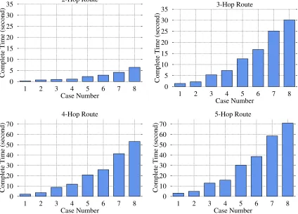
Fig. 3.10 plots the experimental results with the workload in Table 3.1. The bars
show the time consumption of the transmission in each case versus the length of
the path. Apparently, the overhead grows along with file size and path length. For
example, disseminating 2.1MB (case 5) and 4.2MB (case 7) files takes 4.178s and
6.424s respectively for a 2-hop path. The overheads are increased to 25.575s and
30.134s for a 3-hop path. We observe that a MANET is effective for delivering up
to a few Megabytes of data to nearby nodes. For a large file over a long path, e.g.,
case 8 (5.2MB) with a 5-hop path, the overhead may not be acceptable for users.
In practice, considering the dense user population and possible user content sharing,
we expect a short path length for any communication session. In addition to the
overall performance, we also evaluate the breakdown overhead and try to answer the
0 5 10 15 20 25 30 35
1 2 3 4 5 6 7 8
Complete Time (second)
Case Number 2-Hop Route 0 5 10 15 20 25 30 35
1 2 3 4 5 6 7 8
Complete Time (second)
Case Number 3-Hop Route 0 10 20 30 40 50 60 70
1 2 3 4 5 6 7 8
Complete Time (second)
Case Number 4-Hop Route 0 10 20 30 40 50 60 70
1 2 3 4 5 6 7 8
Complete Time (second)
Case Number 5-Hop Route
Figure 3.10: The experimental performance of overhead with different path lengths
Can we use the long-range radio for data delivery? The protocol design could
be much simplified if the long-range radio can carry out the data transmission. We
have conducted the same experiments with direct transmission between two
TinyN-ode devices. The results are shown in Fig. 3.11a. Compared to Fig. 3.10 , the time
consumption with the long-range direct link is much higher. Fig. 3.11b further
com-pares the throughput of direct long-range radio link with hop-by-hop transmission
along a 5-hop path. In this experiment, we use “iperf” tool to record the
through-put every 20 seconds. We observe that hop-by-hop delivery yields a much higher
throughput (with a high variance) even over a long path. Overall, we conclude the
long-range radio works well for small management packets, but is not suitable for
0 50 100 150 200 250
1 2 3 4 5 6 7 8
Complete Time (second)
Case Number
(a)Direct link
100 200 300 400 500 600 700
20 40 60 80 100
Throughput (Kbps)
Time
TinyNode 5-Hop Route
(b)Direct link v.s. 5-hop path
Figure 3.11: TinyNode data delivery performance
3.5.2 Simulation Results
In addition to experiments, we conduct simulation with NS2 to evaluate LAAR
in a large scale network.
3.5.2.1 Simulation Settings
In the simulation, we consider the brochure dissemination application in a mall.
We run the simulation in following two settings.
• Single store: In this setting, there is only one store trying to send out brochures
to the nearby shoppers. We assume that the store periodically broadcasts a
short message including a link to the brochure file over the long-range radio.
The users can use the link to fetch the brochure. We assume that N users receive the short message andα∈[0,1] portion of them will be interested in it, i.e., α×N users will download the brochure.
• Multiple stores: In this setting, there are multiple senders in the mall. Similar
to the previous setting, the senders first use periodical short messages over the
The parameters in NS2 are set as follows. First, we adopt two-ray ground reflection
model and constant speed propagation delay model for wireless signal prorogation.
In addition, each node in our LAAR protocol is set with two radios. We modify
the NS2 to support two wireless interfaces. The frequency of the long-range radio
is set to be 915MHz, and the communication range is configured to be 2500m in
receiving (RX) and 3000m in carrier sensing (CS). The other regular radio (short
range) is configured to work at 2.4GHz, and the RX and CS ranges are set to be 50m
and 100m respectively. For the results shown in this chapter, β is set to 0.9 for the RSSI-guided flooding.
The users in the simulations follow a manhattan grid mobility model [48] with a
maximum moving speed of 2m/s. At an intersection, the probability of going straight
is 0.5 and taking a left or right is 0.25 each. We generate mobility traces with different
numbers of users, and in each trace, users randomly select the initial positions inside
a store or on a corridor. For all the tested protocols, we set RREQ’s default TTL
to 5 if applicable. For speed level with user mobility, the three discrete values in
Algorithm 3 are defined LOW ( <0.5m/s ), MEDIUM ( [0.5,1.5)m/s ), and HIGH (
>1.5m/s ). In addition, ∆H = 2, ∆M = 1, δL = 0, and τ = 3.
3.5.2.2 Single Store
In this setting, we choose Nordstrom (case 7) as our sender and conduct the
simulations with different values of the parameters N and α. For each particular setting, we randomly generate 100 mobility traces for tests, and present the average
values in the following figures.
Path establishment: First, we set N to 200 and 300, and change the value of
In our setting, the average number of neighbors is 23.9 and 34.3 for N = 200 and
N = 300 respectively. The dense topology can lead to a serious congestion in the existing routing protocols, for example, as shown in Fig. 3.12b, to construct 9 (3%×
300) concurrent sessions, DSR, DSR-R0 and AODV-ERS uses 514ms, 598ms and
459ms, respectively. However, in LAAR, the overhead of path establishment remains
low, because our design reduces the number of messages transferred mitigating the
effect of congestion.
0 100 200 300 400 500 600 700 800
1 % 2 % 3 % 4 % 5 %
Time Cost(ms) α LAAR DSR DSR R0 AODV-ERS
(a)N = 200
0 100 200 300 400 500 600 700 800
1 % 2 % 3 % 4 % 5 %
Time Cost(ms) α LAAR DSR DSR R0 AODV-ERS
(b)N = 300
Figure 3.12: Average overhead of path establishment (single store)
0 100 200 300 400 500 600 700
1% 2% 3% 4% 5%
Messages Transferred α LAAR DSR DSR-R0 AOVD-ERS
(a)N = 200
0 100 200 300 400 500 600 700
1% 2% 3% 4% 5%
Messages Transferred α LAAR DSR DSR-R0 AOVD-ERS
(b) N = 300
Fig. 3.13 illustrates the number of messages (RREQs) transferred in the entire
network. The bars indicate a similar trend in all the protocols. Our solution LAAR
significantly outperforms the other three protocols.
Overall throughput: We use throughput as an overall performance metric
taking full mobility trace and link breaks into consideration. Since DSR and DSR-R0
use the same path recovery protocol, we do not include DSR-R0 in this test. Instead,
to better study the impact of stale routes in the cache, we evaluate a DSR protocol
that does not use route cache.
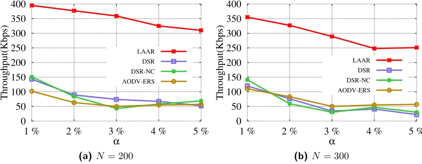
The results are compared in Fig. 3.14. LAAR maintains a high throughput with
different α. For example, with N = 300 andα= 3%, the throughputs of DSR, DSR-NC, AODV-ERS and LAAR are, 34.1, 30.7, 50.8, 289.1Kbps. LAAR’s throughput is
more than five times the throughput of the second best protocol, AODV-ERS. The
major reason of the significant improvement is the efficient path recovery protocol in
LAAR. Our solution greatly reduces the overhead and congestion during a recovery
process, and also improves stability of the selected path and the effectiveness of the
route cache. 0 50 100 150 200 250 300 350 400
1 % 2 % 3 % 4 % 5 %
Throughput(Kbps) α LAAR DSR DSR-NC AODV-ERS
(a)N = 200
0 50 100 150 200 250 300 350 400
1 % 2 % 3 % 4 % 5 %
Throughput(Kbps) α LAAR DSR DSR-NC AODV-ERS
(b)N = 300
3.5.2.3 Multiple Stores
Finally, we test with three stores, Target (case 3), AT&T (case 5) and Nordstrom
(case 7) as our senders. Each store tries to disseminate its brochure listed on Table 3.1.
In our configuration, the α for each store’s brochure is the same. Thus, the total number of transmissions in the network is 3×α×N. We collect the throughput from each transmission session and show the average result for each differentα value.
0 50 100 150 200 250 300 350
1 % 2 % 3 % 4 % 5 %
Throughput(Kbps) α LAAR DSR DSR-NC AODV-ERS
(a)N = 400
0 50 100 150 200 250 300 350
1 % 2 % 3 % 4 % 5 %
Throughput(Kbps) α LAAR DSR DSR-NC AODV-ERS
(b) N= 500
Figure 3.15: Average throughput in multiple stores (3 stores)
Overall throughput: Fig. 3.15 plots the throughput with different values of
α when N = 400,500. Obviously, LAAR performs the best among the four tested protocols. For example, in Fig. 3.15a, the throughputs of LAAR, DSR, DSR-NC,
AODV-ERS are 327.4, 67.0, 32.5, 54.4Kbps with α = 3%, respectively. We also find that the throughput of LAAR is not always inversely proportional to the increase
of α. For instance, in Fig. 3.15b, the throughputs are 306.1, 334.4Kbps for α = 1%,2%. With more users involved in the transmission, our techniques of proactive path recovery and route cache management wii be more effective helping improve the
throughput performance.
0 50 100 150 200 250 300
400 500 600 700 800
Throughput(Kbps)
N
LAAR DSR DSR-NC AODV-ERS
(a)α= 5%
0 50 100 150 200 250 300
400 500 600 700 800
Throughput(Kbps)
N
LAAR DSR DSR-NC AODV-ERS
(b) α= 15%
Figure 3.16: Average throughput in multiple stores (3 stores)
3.6
Summary
This chapter presents LAAR, a new dual radio model for smartphone-based
Ad-Hoc networks. We integrate a long-range radio to help improve the performance
of path establishment and recovery which are critical components in the routing
protocols. The experimental and simulation results show that LAAR dramatically
CHAPTER 4
PASSIVE DELIVERY IN AD-HOC NETWORKS
In Chapter 3, we focus on short message dissemination in the proximity. It
repre-sents a category of applications with high potential if communication between nearby
devices are well supported. For example, a user may want to share his recent tweets
or facebook messages with other people sitting in the same room; a police car on
site of car crash may disseminate the accident information to other cars within one
mile distance; a student in library may chat with his friend in another classroom via
instant messenger; a bunch of sport fans may want to share the comments with each
other on the same game they enjoyed; a victim of crime or natural disasters may want
to ask for help when there is no cellular network or not cannot use it. The current
location-based service architecture is still based on a centralized client-server model,
where a user submits his location to a server and obtains the customized data he
needs. This conventional model quite limits the application scope and may hinder
wide deployment of location related mobile applications because of the following
dis-advantages. First, it requires Internet connection even when a sender and receiver
are adjacently located, which will unnecessarily increase the Internet traffic burden
and users’ bandwidth cost. With this requirement, in addition, applications are not
robust against catastrophic infrastructure failures. Furthermore, a data consumer has
to have prior knowledge of the data providers, e.g., the URL of the server. There is
no general channel for users to browse all available service resources nearby without
Scan range
Scanning Node Node with Data
Message Delivery
Figure 4.1: Passive Broadcast Model
We argue that Ad-Hoc network model is a complementary alternative that can
effectively help solve all the above issues. In practice, however, creating and
maintain-ing a direct link between two nearby devices which is the buildmaintain-ing block of an ad-hoc
network is costly. For example, both Bluetooth and WiFi-Direct require a slow initial
phase of discovering nearby peers and handshaking to establish a connection. It is
especially inefficient for transferring a small amount of data. In addition, connected
link may bring with it a security risk because one device might be able to access all
exposed services on the connected device (e.g., in Bluetooth). In this chapter, we
build a local data dissemination system upon a new communication model, called
passive broadcast. It is a connectionless and receiver-initilized model where each node
periodically scans other nodes in the communication range and obtains their data if
available (see Fig. 4.1, i.e., each scan is a many-to-one communication. The
repre-sentative carriers of passive broadcast in reality include Bluetooth and WiFi-Direct,
both of which define a mandatary ‘peer discovery’ function to fetch basic information
about nearby devices. This function can be easily extended to implement passive
broadcast mechanism without modifying the existing network protocol stack. In
pas-sive broadcast, the cost for establishing and maintaining direct links is negligible
and our experiments show that the communication range is expanded compare to
of fetching messages from multiple nearby devices is desirable for applications that
spread messages in the proximity.
4.1
Related Work
This work is related to prior research on mobile social networks, overlay P2P
dissemination, and delay tolerant networks. Information dissemination has become
more and more important in mobile social networks, such as [49–51], which aim
at data dissemination in resource-constrained opportunistic networks, broadcasting
from superusers and ferrying messages in intermittently connected mobile networks.
Point&Connect [52] implements pointing gestures of moving one device towards
an-other in order to enable spontaneous device pairing. Musubi [53] provides a
decentral-ized trusted social services on personal mobile devices. And BubbleRap [54] utilizes
group membership information to improve standard unicast routing. In [55], the
au-thors propose a gossiping-based approach, where each node forwards a message with
some probability, to reduce the overhead of the routing protocols. 7DS [56] is
devel-oped to address network disruption problem in mobile networks by providing
store-carry-forward communication. However, it only concerns data as store-store-carry-forward
manner for disruption-tolerant applications which is very limited. [57] proposes to
use data diffusion to reduce the query delay in DTNs. They use theoretical
mod-els to analyze the data diffusion process and compare the performance of the their
proposed diffusion schemes in terms of diffusion speed and query delay. In addition,
there is other prior work that helps better understand characteristic of DTNs such
as [58–61]. For example, [58] is the rst to study multicast in DTNs from the social
network perspective. They study multicast in DTNs with single and multiple data
items, investigate the essential difference between multicast and unicast in DTNs,
and formulate relay selections for multicast [59] studies human contact-based traces
multicast messages. The authors in [60] compared the asymptotic performance of
Interest-Based forwarding and from both the theoretical and experimental point of
view. And SimBet [61] first introduces social network analysis in the context of delay
tolerant networks. It uses ego-centric centrality and its social similarity. However, the
focus of our problem is based on a different communication model and our objective
is different. Passive broadcast is a receiver-initialized connectionless communication
based on many-to-one delivery in each scan. Moreover, we target on a distributed
and collaborative solution that efficiently disseminate messages in proximity.
One project closely related to our passive broadcast model is called Dythr [62]
which lets a phone broadcast a WiFi hotspot with the SSID being the message.
This method actually is from the opposite direction of ‘active’ delivery as every node
frequently injects messages into the wireless channel. In [63], Huang et al. proposed
PhoneNet. This method uses a central server to establish links between devices
connected to a WiFi network and then allows devices connected on local networks to
connect directly. In [64], the authors use Bluetooth service discovery protocol to find
common interests between two users. Similar to our proposed work, no connection is
established and each user stores the keyword about his interest in Bluetooth service
ID. However, this work is for two-user communication while our problem is set in
a multiple user environment and our goal is to determine each device’s schedules to
achieve the efficiency.
4.2
System Model
Our target problem in this chapter is to enable nearby smartphone users to share
information. In this section, we introduce basic components and sketch of our
4.2.1 Communication Model
Our solution is based on the new passive broadcast communication model, where
each sender buffers its broadcast data locally and the receiver initializes the
trans-mission and fetches all available data from nearby nodes. In this model, when having
a message to deliver, a node puts it in a buffer, but does not know when the message
will be sent. On the other hand, each node periodically scans other nodes in the
communication range and obtain the data in their buffers if available, i.e., each scan
is a many-to-one communication.
We have implemented this model based on the mandatary ‘peer discovery’ function
in both Bluetooth and WiFi-Direct. In the rest of this chapter, we take Bluetooth as
a platform instance to introduce our solution. Basically, we use the field of ‘device
name’ to carry target payload data. When a user intents to send a message, he assigns
the message to his phone’s Bluetooth device name. When other phones conduct peer
discovery, the message will be sent over. The length of device names is usually limited,
e.g., a Bluetooth’s device name in Android can be up to 248 bytes. A large message
can be fragmented to fit in and a phone can periodically change the device name to
rotate multiple messages or fragments.
4.2.2 Smartphone Operations and States
Assume there arensmartphone nodes ({p1, p2, . . . , pn}) and this chapter considers a network model where all the phones are within each other’s Bluetooth
communica-tion range. There are two basic operacommunica-tions for each smartphone pi, scan and update message. The first operation is the regular peer discovery process while the second
one is to change its own device name to a new message. Update message operation
can be finished instantly. But scan process has a long overhead. For Bluetooth,
ac-cording to the standard and our experiments, a scan operation usually takes 10∼12
phone is conducting scan (peer discovery), it is in scanning phase; otherwise, it is
inidle phase. For each message, we define itsactive periodas the duration when the
message is available for scanning, i.e., after the message is put on the device name
and before it is replaced by the next message. If a phone finishes a complete scan
during a message’s active period, the message will be surely scanned by the phone.
If the active period starts or ends during a scanning process, the phone has a
cer-tain probability to receive the message. We will present detailed analysis later in
Section 4.4.
We assume that the scan schedule has been pre-configured by each phone based on
its own performance concerns, e.g., power consumption and urgency of getting new
messages. We use Ti to represent pi’s scan interval which is defined as the interval between the end of the prior scan and the beginning of the next scan, i.e., the length
of pi’s idle phase. Additionally, we use Ui to indicate the message update interval of pi, i.e., pi changes its device name once every Ui time units. Different from Ti,
Ui’s value can be dynamically changed as it does not incur any extra computation overhead or power consumption. Furthermore, we define S as the length of scanning phase, which is a constant for all phones.
In our solution, each phone and each active message has a unique identifier defined
as follows:
• Phone ID: In this chapter, we use the MAC address as each phone’s identity.
When scanning nearby devices, a phone automatically obtains their MAC
ad-dresses and is able to recognize these phones later.
• Message ID: Each message can be identified by its owner’s MAC address and
a local index number. For example, aa:bb:cc:dd:ee:ff.12 represents a message
from the phone with a MAC address of aa:bb:cc:dd:ee:ff and its index number
on that phone is 12. In our solution, each index number is incremental with
4.2.3 Message Format
In our solution, the device name is divided into two segments, header and payload.
Similar to other network protocol, ‘header’ field contains control and management
data and ‘payload’ stores the messages being broadcast. The header includes the
following fields:
• Scan intervalT: Each phonepi uses one byte to represent its own scan interval
Ti in the unit of second.
• Index range of active messages: Each phone uses two bytes to specify the index
number range of its active messages. We assume each user apply the policy that
only the most recent messages are considered for dissemination, e.g., the most
recent 10 messages, and the messages generated in the past 5 hours.
• Message reception feedback: Each phone includes a message reception feedback
to indicate the current state of the reception. Our solution uses a simple bitmap
to represent this feedback information. Namely, every message is flagged by one
bit in the feedback, ‘1’ indicates ‘received’ and ‘0’ means ‘absent’. We assume
that a functionf can convert a MAC address to a numeric value, thus all phones can be ordered according to their MAC addresses. In the bitmap feedback, the
messages from different phones are ordered by their owners’ MAC addresses.
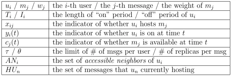
The following Table 4.1 lists some notations we use in the rest of the chapter.
n/pi number of smartphones/the i-th phone
Ti/Ui scan interval / update interval of pi
S execution time of one scan
ti execution time for pi to receive all messages
f a function that converts a MAC address to a numerical value
ki number of messages generated by pi
M set of all message IDs in the network
4.3


](https://thumb-us.123doks.com/thumbv2/123dok_us/1026216.1602759/62.612.116.528.78.289/complete-dierent-smartphones-scenario-timewith-dierent-allphones-scenario.webp)
![Figure 4.14: Average complete time with different α, while ki = Random[5, 30] andTi = Random[5, 30]](https://thumb-us.123doks.com/thumbv2/123dok_us/1026216.1602759/63.612.207.431.290.444/figure-average-complete-time-dierent-random-andti-random.webp)