i
tif c n
e C
i o
c n
S f
l e
a r
n e
o n
i c
t e
a 2
nr 0
et 1
1
n I
ISC 2011
Proceeding of the International Conference on Advanced Science,
Engineering and Information Technology 2011
Hotel Equatorial Bangi-Putrajaya, Malaysia, 14 - 15 January 2011
ISBN 978-983-42366-4-9
ISC 2011
International Conference on Advanced Science, Engineering and Information Technology
ICASEIT 2011
Cutting Edge Sciences for Future Sustainability
Hotel Equatorial Bangi-Putrajaya, Malaysia, 14 - 15 January 2011
SR
IE AUNVIIT
NI
ESE
D K
O B
IN N
R AG
JA A
L S
A A
E N
P M
N A
A L
U A
T Y
A S
S A I
REP
N I
NOI TAI COSSA STNEDUTS NA IENSOD Organized by Indonesian Students Association Universiti Kebangsaan Malaysia Proceeding of the
Performance Comparison between Sliding Mode
Control with PID Sliding Surface and PID Controller
for an Electro-hydraulic Positioning System
Rozaimi Ghazali#, Yahaya Md Sam#, Mohd Fua’ad Rahmat#, Abd Wahab Ishari Mohd Hashim*, Zulfatman# #
Department of Control and Instrumentation Engineering, Universiti Teknologi Malaysia UTM Johor Bahru, Skudai, 81310, Malaysia
Tel.:+607-5535902, E-mail: [email protected], [email protected]
*International Campus, Universiti Teknologi Malaysia Jalan Semarak, Kuala Lumpur, 54100, Malaysia Tel.:+603-26154964, E-mail: [email protected]
Abstract— In this paper, the position tracking performance of an electro-hydraulic hydraulic servo (EHS) system using sliding mode control (SMC) with proportional-integral-derivative (PID) sliding surface is presented. The dynamics of the EHS system in modelling process are developed by consider its nonlinearities incorporating a friction model. Then, SMC with PID scheme is derived from the developed dynamics equation and stability of the control system is theoretically proven by Lyapunov theorem. Finally, simulation work is demonstrated and the result shows the proposed controller can achieve better tracking performance compared with conventional PID controller with good accuracy for any desired trajectory.
Keywords— sliding mode control, electro-hydraulic servo system, position tracking control, PID sliding surface.
I. INTRODUCTION
Electro-hydraulic servo (EHS) system has emerged a great interest in various engineering applications due to its advantages as an actuator in providing high forces with compact design [1]. The sophisticated design of EHS system with the versatility of electronic and hydraulic components offers a great performance and improvement for wide range of applications such as aircrafts [2], manufacturing machines [3], fatigue testing [4] and automotive application [5]. It is established that the EHS system can be more well-known and crucial nowadays.
It is well-known that an EHS system is typically a complicated system suffers from nonlinearities, uncertainties and disturbances. These inconveniences may lead to degradation of control performance in force, pressure or position tracking of EHS system. Nonlinear flow/pressure characteristics, fluid compressibility, actuator friction and internal/external leakages are identified as the major sources of nonlinearity exist in the EHS system [6]. Recently, authors in [7] discussed the mathematical model of the EHS
system by including the effect of compressibility, external leakage in actuator and internal leakage in the servo valve. Most of proportional flow valves suffer from hard nonlinearities such as dead-zone due to asymmetric overlap in the spool valve design [8, 9]. Besides, the friction phenomena are also affect the tracking performance and often considered as a nonlinear model in developing the dynamics equation of EHS system [10].
SMC is recognized as a one of the most potential approach in nonlinear control field and has been proved to the problem of maintaining the stability for controlling many classes of model that are subjected to parameter variations and external disturbances [19]. SMC has widely implemented in many engineering applications including pneumatic systems [20], active suspension systems [21] and active magnetic bearing systems [22]. Current study has been published by author in [23] utilizing the second-order SMC for electromechanical plant. The experimental application is an extended work presented in [24] using the proportional-integral-derivative sliding surface. In [25], the sliding surface is augmented with an integral action and has improved the tracking performance compared with the conventional design.
In this paper, the position tracking control performance of EHS system is evaluated using SMC with PID sliding surface. The nonlinear dynamics model consists of servo valve and hydraulic actuator incorporating with friction model is derived. Based on the EHS model, the SMC control law is developed and the stability is analysed in the sense of Lyapunov theorem. Afterward, position tracking control is performed and comparison with the conventional PID controller is presented.
II. ELECTRO-HYDRAULIC SERVO SYSTEM MODEL
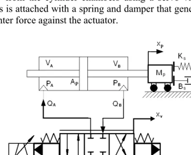
Dynamics equation of EHS system consist of servo valve and hydraulic actuator as illustrated in Fig. 1. The hydraulic actuator motion is controlled by modulating the hydraulic oil flow from the cylinder chambers using a servo valve. The mass is attached with a spring and damper that generates the counter force against the actuator.
Fig. 1 Electro-hydraulic servo system configuration
A. Servo valve model
In the electronic design, the spool valve position in servo valve is driven by the torque motor. The electrical signal to drive the current to be used in coil as represented in (1).
L R I
dt dI
V = C+ C (1)
The servo valve dynamics in (2) can be considered as second-order system relates the current drive from the torque motor and the spool valve position.
2 2
2 2
2 n n
v n v I dt dx dt x
d +
ξω
+ω
=ω
(2)In mechanical design of servo valve, critical-centred is considered where the spool valve is unexposed from flow leakages and dead-zone problems for each port. The servo valve control the flows in each chambers in the actuator can models from the orifice equations. For the ideal orifice equation:
Q= Kxv ΔPV (3) The flow relations for each chambers are given in (4) and (5) by neglecting the internal leakages effects in servo valve [26]. ⎪⎩ ⎪ ⎨ ⎧ − − = R A v A A S v A A P P x K P P x K Q 0 0 < ≥ v v x x (4) ⎪⎩ ⎪ ⎨ ⎧ − − − − = B S v B R B v B B P P x K P P x K Q 0 0 < ≥ v v x x (5)
where the coefficient gain is assumed to be
B
A K
K
K = = for a symmetrical valve.
B. Hydraulic actuator model
The hydraulic actuator is modeled from the dynamics of volume of each chamber as follows:
)
( s p
p line
A V A x x
V = + + (6)
)
( s p
p line
B V A x x
V = + − (7)
where Vline is the volume of the pipeline and the zero position is located at the centre of the cylinder. From the flows and volume equations, pressure from each chamber can be determined by defining the relation between flow rate, bulk modulus, external leakages and volume rate.
dt dt dV q q Q x x A V P A a ab A p s p line
A
∫
⎟⎠ ⎞ ⎜ ⎝ ⎛ − − − + + = ) (
β
(8)dt Q q q dt dV x x A V
P ba b B
B
p s p line
B
∫
⎟⎠ ⎞ ⎜ ⎝ ⎛ − − − − + = ) (
β
(9)The total force generated from the actuator can be expressed in (10) from the overall dynamics equation of spring, damper, moving mass and friction.
f p s p s p p B A p
p K x F
dt dx B dt x d M P P A
F = − = 2 + + +
2
)
( (10)
C. Friction model
p
f x
dt dz z
F =
σ
0 +σ
1 +α
2& (11)dt
dz is the average of bristle deflection which can be
represented as:
z
x g
x x
dt dz
p p p
) (
0
& &
& −
σ
= (12)
The Stribeck function in (13) is a function where expressing the steady-state friction behavior at a constant velocity.
( ) 0 1 (xp/vsk)2
p e
x
g & =α +α − & (13)
The supply pressure is generates from the pumps and drive to the servo valve. Generally, EHS system is equipped with a pressure regulator to regulate the maximum pressure operating in that system. The continuity dynamics between the pump and servo valve can be written as:
Q Q dt
V
P pump L
t
S =
∫
( − )β (14)
With this dynamics system model, some parameters may impossible to gather and the controller design is more complicated to design. Then, the simplified model can be used in controller design where the EHS system can be represent using third-order perturbed linear model including disturbances and uncertainties as in (15).
) ( ) (
) ( ) (
)
(t A A x t B B x t
x&&p n &&p n &p
& = − +Δ − +Δ
+(Cn+ΔC)u(t)+d(t) (15)
where d(t) consist of external load disturbance, nonlinear friction and leakage. An, Bn and Cn are the nominal system parameters. The bounded uncertainties ∆A, ∆B, ∆C are the uncertainties exist from the unmodeled dynamics.
&x&&p(t)= −Anx&&p(t)−Bnx&p(t)+Cnu(t)+L (16)
The lumped uncertainty is defined by:
L= −ΔAx&&p(t)−ΔBx&p(t)+ΔCu(t)+d(t) (17) and the upper bound of the lumped uncertainty Lmax is
) ( ) ( )
( )
( )
(
max t Ax t Bx t Cu t d t
L =Δ &&p +Δ &p +Δ + (18)
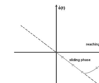
III. SLIDING MODE CONTROL WITH PID SLIDING SURFACE SMC is a type of variable structure control (VSC) developed in the early of 60’s in Russia [19]. It is established that the most crucial step in designing the SMC is the construction of the sliding surface which is expected to response the desired control specifications and performances. The states trajectories are forced to be reached and stayed on the sliding surface as depicted in Fig. 2.
Fig. 2 Phase portrait of a sliding motion in sliding mode control
The PID sliding surface in the SMC design can be expressed in following equation where kp, ki and kd are the PID parameters [23]. For a third-order system, the sliding surface can be defined as in (19).
) ( )
( )
( ) (
0
t e k d e k t e k t
s d
t
i
p + + &
=
∫
τ
τ
(19)The tracking error can be determined as a difference between the trajectory and actual position of the actuator.
) ( ) ( )
(t x t x t
e = r − p (20)
Since the linear model is a third-order model, the third derivative of the error is:
) ( ) ( )
(t x t x t
e&& &&&r &&&p
& = − (21)
The control signal in SMC design consists of equivalent control and switching control where the control action is corresponding with the sliding phase and reaching phase. The equivalent control is determined when s(t) = 0, while the switching control is described when s(t) ≠ 0. The common control structure of SMC can represented as:
) ( ) ( )
(t u t u t
usmc = eq + sw (22)
In sliding mode phase, the tracking error will converge to equilibrium point and the sliding surface is supposed to be
0
)
(
)
(
)
(
t
=
s
t
=
s
t
=
s
&
&&
where in this situation, the trackingerror is trapped in the sliding surface. The equivalent control is obtained when
s
&&
(
t
)
=
0
and the second derivative of the sliding surface,s&&(t)=kpe&&(t)+kie&(t)+kd&e&&(t) (23) By substituting (21) into (23) and let
s
&&
(
t
)
=
0
without lumped uncertainty (L=0), the equivalent control can be defined as:) ( ) ( ( ) ( )
( 1
t e k t e k C k t
ueq = d n p && + i&
−
+kd(&x&&r + Anx&&p +Bnx&p)) (24)
The switching control can be chosen as a sign function of sliding surface [23],
where
λ
,ks∈ℜ+ and sign(s&(t))denotes signum function as:
⎪⎩
⎪ ⎨ ⎧
− =
, 1 , 0
, 1 )) ( (s t
sign &
0 ) (
0 ) (
0 ) (
< = >
t s
t s
t s
& & &
(26)
To verify the stable convergence behavior of nonlinear controller, Lyapunov theorem as a well-known approach is used in stability analysis [10, 16, 18]. Lyapunov function can be chosen to prove the stability as:
) ( 2 1 ) ( 2 1 )
( 2 2
t s t s t
V = + &
(27)
with V(0) = 0 and V(t) > 0 for s(t) ≠ 0. To guarantee the trajectory move from reaching phase to sliding phase and ensure the stability, it is necessary to follow the reaching condition:
V&(t)<0, for s(t)≠0,s&(t)≠0 (28) By substituting (21), (22) and (23) into (28),
) ( ) ( ) ( ) ( )
(t s t s t s t s t
V& = & + & &&
) ( )) ( ) ( )
( ) ( )
( )
(t s t k C s t s t k C k s t k L t s t
s & − d n & − d n s & − d &
=
λ
[
( ) ( ) ( ))]
)
(t s t k C s t k C k k L t
s − d n − d n s− d
≤ &
λ
[
( ) ( ) ( ))]
)
(t s t k C s t k C k k L t
s − d n − d n s − d
≤ &
λ
[
( )( 1) ( ))]
0)
( − + − max <
−
≤ s& t s t kdCn
λ
kdCnks kdL t (29)When the system is in the reaching phase where s(t)≠0 , s&(t)≠ 0 the requirement for SMC parameters to guarantee the stability is
n s
C L k > max ,
n dC k
1 >
λ
and V&(t)is negative definite.The discontinuous function in (25) caused a chattering in the control signal. To avoid the chattering effect that can be harm to the system, the hyperbolic tangent function with boundary layer φ can be proposed [23].
)
tanh( )
( ) (
ϕ
λ
st k st
usw s
& +
= (31)
IV. RESULTS AND DISCUSSION
In simulation study, the parameters used in nonlinear model of EHS system can be seen in Table 1. In the early design of SMC, the nominal values of EHS system can be identified using linearization of the EHS model or any identification techniques [8, 27]. The selection of sliding surface parameters based on the identified third-order model.
λ=100 and ks=10 is used in the numerical simulation where ks is set to maximum voltage that can be operated by the system. To reduce the chattering effect, the φ parameter is set by sensitivity method until the controller achieves the adequate performance. The trade-off between the chattering and high-speed performance should made in tuning this parameter.
To simulate the friction model, the nonlinear Lu-Gre friction is implemented in the dynamics of the EHS system where parameters are stated in Table II.
TABLE I
PARAMETERS OF EHS SYSTEM [7]
Hydraulic actuator and Servo valve parameters
Description Symbol Value
Total mass Mp 9 kg
Damping coefficient Bs 2000 Ns/m
Spring stiffness Ks 10 Nm
Total actuator displacement Xs 0.1 m
Piston area Ap 645x10-6 m2
Servo valve damping ratio ζ 0.48
Servo valve natural frequency ω 534 rad/s
Servo valve coil resistance Rc 100 Ω
Servo valve coil inductance Lc 0.02 A
Servo valve gain K 2.38x10⁻⁵ m5/2/kg1/2
Bulk modulus of hydraulic fluid β 1.4x10⁹ N/m2
Pump pressure PS 2.1x10⁷ Pa
Return pressure PR 0 Pa
TABLE II FRICTION PARAMETERS
Description Symbol Value
Stribeck velocity vsk 0.032 m/s
Coulomb friction α0 370 N
Stribeck friction α1 217 N
Viscous friction α2 2318 N/m/s
Bristles stiffness σ0 5.77x10⁶ N/m
Bristles damping σ1 2.28x10⁴ N/m/s
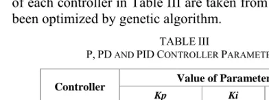
P, PD and PID controllers are used for performance comparison in the position tracking control. The parameters of each controller in Table III are taken from [7] which have been optimized by genetic algorithm.
TABLE III
P, PD AND PID CONTROLLER PARAMETERS
Controller Value of Parameter
Kp Ki Kd
P 59.7117 0 0
PD 206.1246 0 1.1490
PID 221.0415 3.5260 1.2573
stay on that surface until meet the equilibrium point where the error and derivative of error approaching to zero. It is
also can be seen that no chattering occur in sliding surface and its control effort during the position tracking control.
0 0.05 0.1 0.15 0.2 0.25 0.3 0.35 0.4 0.45 0.5
0 0.01 0.02 0.03 0.04 0.05 0.06
Time (s)
Di
sp
la
cemen
t (m)
Position Tracking Control for Xr=0.05m
Desired Trajectory SMC P-controller PD-controller PID-controller
Fig. 3 Tracking performance of different controller for position control
0 0.05 0.1 0.15 0.2 0.25 0.3 0.35 0.4 0.45 0.5
-2 0 2 4 6 8 10 12 14 16
TIme (s)
V
o
lt
age (V)
Usmc
Fig. 4 Control effort of SMC with PID sliding surface
-0.01-2 0 0.01 0.02 0.03 0.04 0.05 0.06
-1.5 -1 -0.5 0 0.5
e(t)
de
/d
t
Phase Plot of Tracking Error
Sliding phase
Reaching phase
TABLE IV ERROR ANALYSIS
Control
method SMC P-controller PD-controller
PID-controller
Steady state error
1.8917x10⁻⁵ 1.6640x10⁻⁴ 9.9614x10⁻¹¹ 2.666x10⁻⁵
Mean- square-error
8.2324x10⁻⁵ 2.7210x10⁻⁴ 1.1171x10⁻⁴ 1.0709x10⁻⁴
Based on the error analyses, control effort and observation on the tracking performance, the SMC provides more convinient and better performance in position tracking control and ensured that the control system in under stable condition. Is it found that equivalent control ueq can be
neglected in this simulation study. The assumption where the position tracking is not one of reaching sliding surface, but one of near or already on sliding surface can be made. In applications where stability in not an issue, the term ueq often
has a minimal effect in system response, so the equivalent control can be omitted [20]. Consequently, a simple robust control method without much control effort can be made with this proposed design.
V. CONCLUSIONS
In this study, the performance of SMC, P, PD and PID controllers are evaluated for position tracking control. The Lyapunov approach is used in theoretical analysis in developing the SMC with PID scheme and to ensure that the system is under stable condition. The numerical simulation study shows that the proposed controller provides better performance in tracking accuracy and time response. The control effort produced from SMC without the chattering effect also is practical to be used in real application. In conclusion, a simple control method without much control effort and better performance can be made with the SMC design based on PID sliding surface instead of using conventional PID controller.
ACKNOWLEDGMENT
The authors would like to thank Universiti Teknologi Malaysia (UTM) and Ministry of Science, Technology and Innovation (MOSTI) Malaysia for their support.
REFERENCES
[1] H. E. Merrit, Hydraulic Control Systems, John Wiley & Sons, Inc.,
New York, 1967.
[2] M. Karpenko and N. Sepehri, “Hardware-in-the-loop simulator for
research on fault tolerant control of electrohydraulic actuators in a
flight control application”, Mechatronics, vol. 19, pp. 1067-1077,
2009.
[3] J. Pluta, “Hydraulic press with LS system for modelling of Plastic
working operations”, Acta Montanistica Slovaca, vol.13, pp. 152-157,
2008.
[4] J. Ruan, X. Pei and F.M. Zhu, “ Identification and Modeling of
Electrohydraulic Force control of the material test system (MTS)”,
Journal of Physics: Conference Series, vol.48, pp. 1322-1326, 2006.
[5] Y. M. Sam, J. H. S. Osman and M.R.A. Ghani, “A class of
proportional-integral sliding mode control with application to active
suspension system”, System and Control Letters, vol. 51, pp. 217-223,
2004.
[6] M. Jelali and A. Kroll, Hydraulic Servo-Systems: Modelling,
Identification and Control, Springer, 2003.
[7] M. Kalyoncu and M. Haydim, “Mathematical modelling and fuzzy
logic based position control of an electrohydraulic servosystem with
internal leakage”, Mechatronics, vol. 19, 2009, pp.847-858.
[8] T. Knohl and H. Unbehauen, ”Adaptive position control of
electrohydraulic servo systems using ANN”, Mechatronics, vol. 10,
pp. 127-143, 2000.
[9] W. M. Bessa, M. S. Dutra and E. Kreuzer, “Sliding mode control with
adaptive fuzzy dead-zone compensation of an electro-hydraulic
servo-system”, Journal of Intelligent and Robotic Systems, vol. 58, pp. 3-16,
2010.
[10] M. Mihajlov, V. Nikolic and D. Antic, “Position control of an
electro-hydraulic servo system using sliding mode control enhanced by fuzzy
PI controller”, Facta Universitatis, Series: Mechanical Engineering,
vol.1, no.9, pp. 1217-1230, 2002.
[11] Zulfatman and M.F. Rahmat, “Application of self-tuning Fuzzy PID
controller on industrial hydraulic actuator using system identification
approach”, International Journal on Smart Sensing and Intelligent
Systems, vol. 2, no. 2, pp. 246-261, 2009.
[12] S. Cetin and A.V. Akkaya, “Simulation and hydbrid fuzzy-PID control
for positioning of a hydraulic system”, Nonlinear Dynamics, Springer,
DOI:10.1007/s11071-010-9662-1, 2010.
[13] K. Ziaei and N. Sepehri, “Design of a nonlinear adaptive controller for
an electrohydraulic actuator”, Journal of Dynamic Systems,
Measurement and Control, vol. 123, pp. 449-456, 2001.
[14] A. Kirecci, M. Topalbekiroglu and I. Eker, “Experimental evaluation
of a model reference adaptive control for a hydraulic robot: a case
study”, Robotica, vol. 21, pp.71-78, 2003.
[15] N. Sepehri and G. Wu, “Experimental evaluation of generalized
predictive control applied to a hydraulic actuator”, Robotica, vol.16,
pp. 463-474, 1998.
[16] Y. Liu and H. Handroos, “Sliding mode control for a class of
hydraulic position servo”, Mechatronics, vol. 9, pp. 111-123, 1999.
[17] C. W. Chuang and L. C. Shiu, “CPLD based DIVSC of hydraulic
position control systems”, Computers and Electrical Engineering, vol.
30, pp.527-541, 2004.
[18] H. M. Chin, J. C. Renn and J. P. Su, “Sliding mode control with
varying boundry layers for an electro-hydraulic position servo
system”, International Journal of Advance Manufacturing
Technology, vol. 26, pp. 117-123, 2005.
[19] C. Edwards and S. K. Spurgeon, Sliding Mode Control: Theory and
Applications, Taylor and Francis, London, 1998.
[20] B. W. Surgenor and N. D. Vaughan, “Continuous sliding mode control
of a pneumatic actuator”, Journal of Dynamic Systems, Measurement
and Control, vol. 119, pp. 578-581, 1997.
[21] Y. M. Sam, and J. H. S. Osman, “Modeling and Control of Active
Suspension System Using Proportional Integral Sliding Mode
Approach,” Asian Journal of Control, vol. 7, no. 2, pp. 91-98, 2005.
[22] A. R. Husain, M. N. Ahmad and A. H. M. Yatim, “Chattering-free
sliding mode control for an active magnetic bearing system”, World
Academy of Science, Engineering and Technology, vol. 39, pp.
385-391, 2008.
[23] I. Eker, “Second-order sliding mode control with experimental
application”, ISA Transactions, vol. 49, pp. 394-405, 2010.
[24] I. Eker, “Sliding mode control with PID sliding surface and
experimental application to an electromechanical plant”, ISA
Transactions, vol. 45, pp. 109-118, 2006.
[25] I. Eker and S. A. Akmal, “Sliding mode control with integral
augmented sliding surface: design and experimental application to an
electromechanical system”, Electrical Engineering, vol. 90, pp.
189-197, 2008.
[26] G. A. Sohl and J. E. Bobrow, “Experiments and simulations on the
nonlinear control of a hydraulic servosystem”, IEEE Transactions on
Control Systems Technology, vol. 7, no. 2, pp. 238-247, 1999.
[27] R. Ghazali, Y. M. Sam, M. F. Rahmat and Zulfatman, “Open-loop and
closed-loop identification of an electro-hydraulic actuator system”,
Proc. 4th