786
©IJRASET: All Rights are Reserved
A Review on Augmentation of Voltage Stability
Using Optimization Technique
Ms. Dhruvi Chopra1, Prof. Y. D. Shahakar2
1, 2
Department of Electrical Engineering, P.R. Pote COE & M, Amravati
Abstract: Present day power systems are being operated closer to their stability limits due to economic constraints. Maintaining a stable and secure operation of a power system is therefore very important and challenging issue. Many traditional and advanced optimization techniques have been proposed for reactive power dispatch to improve voltage stability of the power system. In this paper, the importance of voltage stability and optimal reactive power dispatch are discussed. This paper presents review of LP Technique and PSO algorithm for system parameters development for improving voltage stability and voltage profile improvement. The different optimization techniques for improving voltage stability are studied. The advanced Particle Swarm Optimization algorithm is tested in IEEE 39 bus system. The performance of PSO is compared with conventional linear programming methods.
Keywords: Voltage Stability, Linear Programming, PSO, Voltage Profile Improvement, Fast Decoupled Load Flow, L-Index
I. INTRODUCTION
Voltage stability refers to the ability of power system to maintain steady voltages at all the buses in the system after being subjected to a disturbance from a given initial operating point. The system state enters the voltage instability region when a disturbance or an increase in load demand or alteration in system state results in an uncontrollable and continuous drop in system voltage.
Enhancing the voltage stability indirectly means reactive power control. Any changes in either power demand or system configuration implies increase or decrease in voltage. These changes can lead to system instability which can be improved through reactive power allocation. Reactive power allocation can be done by (a) tap changing transformer (b) changing generator voltages (c) switchable VAR sources.
The optimal reactive power control problem can be stated as the problem of finding the correct value control variables so that the loss can be decreased.
The main advantages of reactive power control are decrease in transmission losses, increase in power transmission capability, improved voltage profile and improved system stability. To obtain optimized reactive power control different objective functions are optimized like to minimize the sum of square of the voltage deviations of the load buses, minimization of sum of squares of voltage stability L-indices of load buses, real power loss minimization, etc [4]. To optimize we use different techniques like PSO, Genetic Algorithm, Fuzzy Logic, Linear Programming, etc [2].
The process of improving something than its current condition is called as Optimization. It is the process of adjusting inputs, mathematical process or device characteristics to get the required output. This process is called as fitness function, objective function or cost function. Particle Swarm Optimization is inspired by behaviour of bird flocking. This algorithm consists of swarm of particles i.e. group of random particles where each single solution is a bird (particle) in the search space. Optimized solution for every particle is determined by fitness function [3]. PSO is based on birds swarm searching for optimal food sources in which direction of birds movement is influenced by its current movement. Linear programming is a simple technique where we depict complex relationships through linear functions and then find the optimum points. The real relationships might be much more complex – but we can simplify them to linear relationships. Linear programming is used for obtaining the most optimal solution for a problem with given constraints. In linear programming, we formulate our real life problem into a mathematical model. It involves an objective function, linear inequalities with subject to constraints [2].
787
©IJRASET: All Rights are Reserved
Consider a system where, n=total number of busses, with 1, 2... g generator busses (g), g+1, g+2... g+s SVC busses (s), g+s+1... n the remaining busses (r= n-g-s) and t = number of OLTC transformers.
A load flow result is obtained for a given system operating condition, which is otherwise available from the output of an on-line state estimator. Using the load flow results, the L-index [7][8] is computed as
(1)
Where j = g+1... n.
The values Fji are obtained from the Y bus matrix as follows [1]:
(2)
Where IG, IL and VG, VL represents currents and voltages at the generator nodes and load nodes. Rearranging (2) we get
(3)
Where are the required values. The L-indices for a given load condition are computed for all load busses. For stability, the bound on the index Lj must not be violated (maximum limit=1) for any of the nodes j. Hence, the global indicator L
describing the stability of the complete subsystem is given by L= maximum of Lj for all j (load buses). An L-index value away from
1 and close to zero indicates an improved system security. For a given network, as the load/generation increases, the voltage magnitude and angles change, and for near maximum power transfer condition, the voltage stability index Lj values for load buses
tend to close to 1, indicating that the system is close to voltage collapse. The stability margin is obtained as the distance of L from a unit value i.e. (1-L) [4].
B. Objective Function
The objective selected for voltage profile improvement is to minimize the sum of the squares of the voltage stability indices (L-index) of all load buses in the system and is as follows:
(4) where Lj is L-index value at load bus j whose value is given in the equation (1)
III.EVALUATIONOFSYSTEMPARAMETERS
A. Constraint Equations for power and control variables
1) Equality Constraints: A Equality constraints of reactive power optimization are the power flow equations. Each node in the system has active and reactive power functions, which are given by [7][8][2]:
(5) (6)
In the above equations, Vi and Vj are the voltages at bus i and j. Gij and Bij are the conductance and susceptance of the line
connecting bus i and j. δij is the phase angle difference of voltage from bus i to j.
2) Inequality Constraints: In the reactive power optimization, generator excitation, on load transformer taps and reactive power compensation capacity (SVC) are selected as control variables. So, the control variable constraints are given as [7][8]:
788
©IJRASET: All Rights are Reserved
The voltage of load bus and value of generator reactive power can be obtained after the PF calculation. They are treated as state variables generally. The state variables constraints are given by:
(8)
,
B. Verror (Ve), Vstability (Vs) and Power loss (Ploss)
To check the effectiveness of the proposed method, the overall performance of the system has been analyzed in terms of the following system parameters. Verror (Ve), Vstability (Vs) and power loss (Ploss) respectively. Vd is desired value set as 1.0 p.u. [7].
(9) (10) (11)
C. Reactive Power Output
From the load flow studies, we can calculate the reactive power ‘Q’ at generator bus ‘i’ is given by, (12) Where, Gij= conductance & Bij= susceptance between buses ‘i’ & ‘j’, Vi& Vjare the voltages at bus i and j,
δij is the phase angle difference of voltage from bus i to j. Gkis conductance of kth transmission line, l is total no. of transmission
lines [7].
IV. FORMULATIONFOROPTIMIZATION
The problem considered for voltage profile improvement is to minimize the sum of the squares of the L-index values of the load buses and it is given by equation (4). Rewriting Vstability (VL) as,
(13)
Consider a system where, K = Total number of control variables with 1,2…T number of OLTC transformers,T+1, T+2…T+G generator excitations and T+G+1…K SVCs,(K=T+G+S). The relation between the net reactive power change at any node due to change in transformer tap settings and the voltage magnitudes can be written as [4][7][8]
(14)
789
©IJRASET: All Rights are Reserved
function of all the load buses with respect to control variables from equation (4) can be expressed by the given matrix [4][7][8]: (16)
Using the Load flow Analysis the sensitivities of the above equation are calculated. The load flow analysis is done by Newton Raphson Method. The equation for the above is given as
Where n is total number of bus and is Jacobian Matrix, which is divided into submatrices as
For Fast Decoupled Load Flow method J2and J3 are equal to zero. Therefore J1 and J4 are given as:
Using the above matrices the sensitivities i.e. the matrix [H] is calculated.
To calculate [H]: Sensitivities of voltage stability VL with respect to real and reactive power injections at all load buses except swing
bus i.e. , ….., ; , ……, using equations: and
By knowing above values objective function sensitivities with respect to control variables i.e. can be estimated
[4][7][8].
V. PROPOSEDOPTIMIZATIONTECHNIQUES
A. Approach for LP Technique in Power System
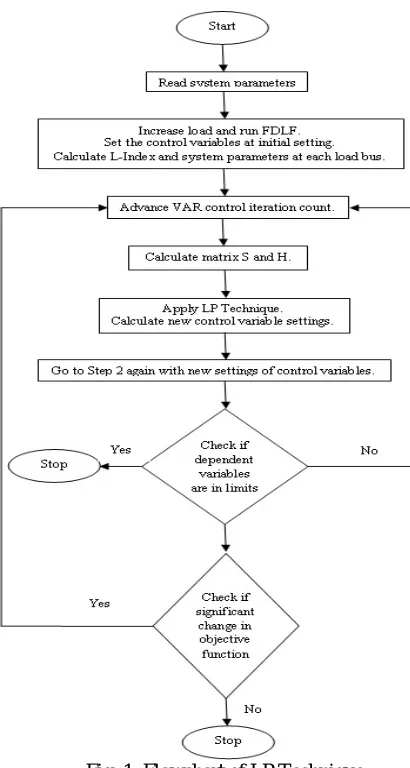
Linear programming is adaptive and more flexibility to analyse the problems. The main advantage of linear programming is its simplicity and easy way of understanding. Linear Programming (LP) is a technique for optimization of a linear objective function, subject to linear equality and linear inequality constraints. Classical optimization techniques such as LP and NLP are efficient approaches that can be used to solve special cases of optimization problem in power system applications[2][7][8]. The flow chart of LP technique is shown in fig 1.
B. Algorithm for PSO method in Power System
790
[image:5.612.101.526.85.472.2]©IJRASET: All Rights are Reserved
Fig. 1 Flowchart of LP Technique Fig. 2 Flowchart of PSO Algorithm
Following are the steps required to perform PSO Algorithm [7]
1) Initialize parameter C1, C2 and constriction factor C.
2) Give initial position and initial velocity for the particle of the swarm.
3) Calculate the fitness values of the particle. Calculate Pb and Gb.
4) Calculate the new velocity using equation
Where is known as the weighting function and is written as:
Where max iter = maximum iteration given by user.
= previous position of the particle, = previous velocity of the particle.
= best fitness of the particle so far, = best fitness of the swarm so far.
5) Now update the position using
6) Calculate the fitness values of the particle and update Pb and Gb.
7) If termination criteria are satisfied go to next step otherwise go to step 4.
[image:5.612.48.253.90.474.2]791
©IJRASET: All Rights are Reserved
proposed in this paper. PSO algorithm is based on the behaviour of swarms. For better results the parameters and weighting function in the PSO algorithm are varied by user. This method is used to optimize the objective function (ΣL2) for IEEE 39 bus system. In the proposed paper calculation for the optimized setting of control variables like OLTC transformer, Generator excitation and Switchable VAR devices, is performed using proposed Algorithms. The analysis shows that PSO algorithm is more efficient and better than LP technique. Different parameters like control variable setting, L-Index, Verror and power loss, are also observed for the better understanding of the system.
VII.ACKNOWLEDGMENT
We would like to acknowledge the Faculties of Electrical Engineering Department, P. R. Pote(Patil) Group of Education Institute College of Engineering and Management, Amravati for their support and guidance. I, Dhruvi Chopra specially want to thank my guide Prof. Y. D. Shahakar for her guidance and constant encouragement towards the work.
REFERENCES
[1] Kessel. P and Glavitsch. H, “Estimating the Voltage Stability of a Power System,” IEEE Transactions on Power Delivery, vol.1, no.3, July 1986 pp. 346-354. [2] J.Qiu and S.M.Shahidehpour, “A new approach for minimizing power losses and improving voltage profile,” IEEE Trans. On Power Systems, vol. 2, no. 2,
May 1987, pp. 287-295.
[3] M. A. Abido, “Optimal power flow using particle swarm optimization, ”International Journal of Electrical Power & Energy Systems, vol. 24, no.7, 2002, pp 563-571.
[4] Dhadbanjan and Yesuratnam,“ Comparison of Optimum Reactive Power schedule with Different Objectives using LP Technique,” Int. Journal of Emerging Electrical Power Systems, Vol.7, no. 3, article.4, 2006, pp. 1-22.
[5] K. Vaisakh, Member, IEEE, and P.Kanta Rao, “Optimum Reactive Power Dispatch Using Differential Evolution for Improvement of Voltage Stability” 978-1-4244-1762-9/08/ C 2008 IEEE.
[6] S. D. Chavan, Nisha P. Adgokar “An Overview on Particle Swarm Optimization: Basic Concepts and Modified Variants” International Journal of Science and Research Volume 4 Issue 5, May 2015. pp 255-260.
[7] K. Rayudu, G. Yesuratnam, K. Surendhar and A. Jayalaxmi, “Voltage Stability Enhancement Based on Particle Swarm Optimization and LP Technique”, 2016 International Conference on Emerging Technological Trends [ICETT].
[8] K. Rayudu, G. Yesuratnam and A. Jayalaxmi, “Ant Colony Optimization Algorithm Based Optimal Reactive Power Dispatch to Improve Voltage Stability,” 2017 International Conference on circuits Power and Computing Technologies [ICCPCT].
[9] K. R. Padiyar, “Power System Dynamics Stability and Control”, Second edition by BS Publications. [10] P. Kundur, “Power System Stability and Control”, McGraw-Hill, Inc.