Position Control of DC Motor Using
Genetic Algorithm Based PID Controller
Neenu Thomas, Dr. P. Poongodi
Abstract
–
The aim of this paper is to design a position controller of a DC motor by selection of a PID parameters using genetic algorithm. The model of a DC motor is considered as a third order system. And this paper compares two kinds of tuning methods of parameter for PID controller. One is the controller design by the genetic algorithm, second is the controller design by the Ziegler and Nichols method. It was found that the proposed PID parameters adjustment by the genetic algorithm is better than the Ziegler & Nichols’ method. The proposed method could be applied to the higher order system also.Keywords
-
DC motor, Genetic algorithm, PID controller, Ziegler Nichols Method
I. INTRODUCTION
Due to its excellent speed control characteristics, the DC motor has been widely used in industry even though its maintenance costs are higher than the induction motor . As a result, position control of DC motor has attracted considerable research and several methods have evolved. Proportional-Integral Derivative (PID) controllers have been widely used for speed and position control of DC motor. This paper endeavors to design a system using Genetic Algorithm. Genetic Algorithm or in short GA is a stochastic algorithm based on principles of natural selection and genetics. Genetic Algorithms (GAs) are a stochastic global search method that mimics the process of natural evolution. Using genetic algorithms to perform the tuning of the controller will result in the optimum controller being evaluated for the system every time. The objective of this paper is to show that by employing the GA method of tuning a system , an optimization can be achieved. This can be seen by comparing the result of the GA optimized system against the classically tuned system.
Neenu Thomas is with the Karunya University, Karunya Nagar, Coimbatore, Tamil Nadu, 641114, India (corresponding author to provide phone: 09943050530; e-mail: [email protected]).
Dr. P. Poongodi, is with the Karunya University, Karunya Nagar, Coimbatore, Tamil Nadu, 641114, India (corresponding author to provide phone: 09363147648; e-mail: [email protected]).
The following section II formulates the system model of a DC motor. The focus of section III is on conventional PID Controller, it’s tuning by Ziegler Nichols Method and how it can be applied to DC motors. A brief review of Genetic Algorithm Based PID Controller is brought up in section IV. Also discusses the structure of the GA based controller and it’s implementation in the system. In section V, simulation results of the corresponding system are obtained and compared.
II. SYSTEM MODEL
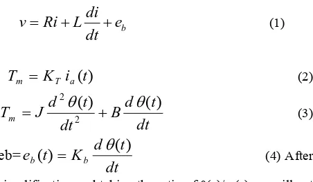
As reference we consider a DC shunt motors as is shown in figure 1. DC shunt motors have the field coil in parallel (shunt) with the armature. The current in the field coil and the armature are independent of one another. As a result, these motors have excellent speed and position control. Hence DC shunt motors are typically used applications that require five or more horse power. The equations describing the dynamic behavior of the DC motor are given by the following equations;
b
di
v
Ri
L
e
dt
=
+
+
(1)
T
m=
K
Ti
a(
t
)
(2)
dt
t
d
B
dt
t
d
J
T
m 2(
)
(
)
2
θ
θ
+
=
(3)
eb=
dt
t
d
K
t
e
b(
)
=
bθ
(
)
(4)After simplification and taking the ratio of θ(s)/ v(s) we will get the transfer function as below,
Θ(s) / v(s)=Kb / [J La S3 + (Ra J+B La)S2 +(Kb2+Ra B)S] (5) Where, R=Ra=Armature resistance in ohm, L=La=Armature inductance in henry ,i=ia= Armature current in ampere ,v= Va=Armature voltage in volts ,eb= e(t)=Back emf voltage in volts, Kb=back emf constant in volt/(rad/sec), K= Kt=torque constant in N-m/Ampere, Tm=torque developed by the motor in N-m, θ(t)=angular displacement of shaft in radians, J=moment of inertia of motor and load in Kg-m2/rad, B=frictional constant of motor and load in N-m/(rad/sec)
A. Numerical Values
The DC motor under study has the following specifications and parameters
a) Specifications
2hp, 230 volts, 8.5 amperes, 1500rpm
b) Parameters:
Ra=2.45 ohm, La=0.035 H, Kb=1.2 volt/(rad/sec), J=0.022Kg-m2/rad ,B=0.5*10^-3 N-m/(rad/sec).The overall transfer function of the system is given below,
III. TUNING OF PID CONTROLLER USING CONVENTIONAL APPROACH
A. Conventional Approach - Ziegler Nichols Method
The control system performs poor in characteristics and even it becomes unstable, if improper values of the controller tuning constants are used. So it becomes necessary to tune the controller parameters to achieve good control performance with the proper choice of tuning constants. Controller tuning involves the selection of the
best values of kc, Ti and TD (if aPID algorithm is being used). This is often a subjective procedure and iscertainly process dependent. It is widely accepted method for tuning the PID controller. The method is straightforward. First, set the controller to P mode only. Next,set the gain of the controller (kc) to a small value. Make a small set point (or load) change and observe the response of the controlled variable. If kc is low the response should be sluggish. Increase kc by a factor of two and makeanother small change in the set point or the load. Keep increasing kc (by a factor of two) until the response becomes oscillatory. Finally, adjust kc until aresponse is obtained that produces continuous oscillations. This is known asthe ultimate gain (ku). Note the period of the oscillations (Pu). The steps required for the method are given below. We have to set the integral and derivative coefficients are zero. Gradually increase the proportional coefficient from 0 to until the system just begins to oscillate continuously. The proportional coefficient at this point is called the ultimate gain Ku. And the period of oscillation at this point is called ultimate period Pu. The Ku=gain margin of the system and the Pu=(2*pi)/wcg. Where, the wcg. is the gain cross over frequency. Gain margin is the reverse of amplitude ratio. The control lawsettings are then obtained from the following table 1 and also the wcg. PID gain values after simulation is given below table 2,
Table 1 Control law settings
Controller Kp Ti Td
P Ku/2
PI Ku/2.2 Pu/1.2
PID Ku/1.7 Pu/2 Pu/8
[image:2.595.45.271.87.219.2]
Table 2 PID controller gain values
Gain Coeff. Kp Ki Kd
Values 18 0.045 0.0182
Fig2. Response of the system with conventionally tuned PID controller
B. Analysis of conventionally tuned PID controller
From the above response, we can analyze the system. We can analyze the following parameters:
• Rise time, tr
• Maximum Overshoot, Mp • Settling time, ts
The rise time, tr is the time taken to reach 10 to 90 % of the final value is about 0.2 sec. The Maximum Overshoot, Mp of the system is approximately 1.01. Finally the Settling time, ts is about 0.25sec. From the analysis above, the system has not been tuned to its optimum. So in order to achieve the following parameters we have to go for genetic algorithm approach. Our system requirements are given below,
Table 3 System Requirements
Maximum overshoot
Rise time(sec)
Settling time(sec) System
specifications
1 < 0.2 <0.25
IV. TUNING OF PID CONTROLLER USING GENETIC ALGORITHM APPROACH
A. Overview of Genetic Algorithm
GA is a stochastic global adaptive search optimization technique based on the mechanisms of natural selection. Recently, GA has been recognized as an effective and efficient technique to solve optimization problems. Compared with other optimization techniques. GA starts with an initial population containing a number of
chromosomes where each one represents a solution of the problem which performance is evaluated by a fitness function.
Basically, GA consists of three main stages: Selection, Crossover and Mutation. The application of these three basic operations allows the creation of new individuals which may be better than their parents. This algorithm is repeated for many generations and finally stops when reaching individuals that represent the optimum solution to the problem. The GA architecture is shown in Fig.3.
Fig. 3 Genetic Algorithm Architecture
B. Implementation of GA based PID controller
Fig 4 Block diagram of the entire system
[image:4.595.45.290.86.182.2]
Table 4 Parameters of GA
GA property Value/Method
Population Size Maximum Number of
Generations
60 20 Performance
index/fitness function Mean square error Selection Method Normalized Geometric
Selection Probability of
selection 0.05
Crossover Method Arithmetic Crossover Number of crossover
points 3
Mutation Method Uniform Mutation
Mutation Probability 0.1
After giving the above parameters to GA the PID controllers can be easily tuned and thus system performance can be improved. The system performance can be given below,
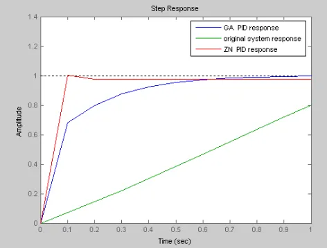
[image:4.595.315.551.481.660.2]Fig 5 Response of the system with GA based PID controller Table 5 GA based PID controller gain values
Gain parameters
Kp Ki Kd
Gain Values
19.88 0.1376 0.5578
V. ANALYSIS OF RESULT
In the implementation of conventionally tuned PID
controller is not getting the accurate results but the proper optimized gain values of controller are obtained with the implementation of GA based PID controller. Comparative results are given below,
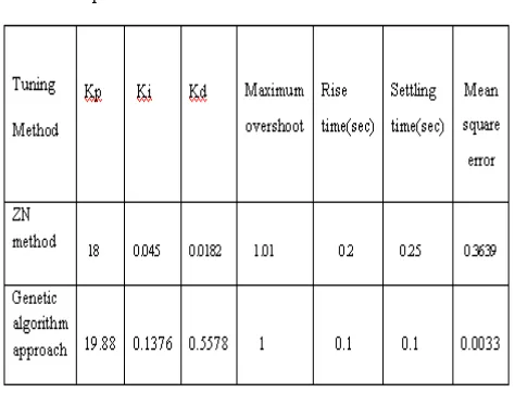
Table 6.comparison of results
VI. CONCLUSION
The designed PID with GA has much faster response than
response of the classical method. The classical method is good for giving us as the starting point of what are the PID values. However the GA designed PID is much better in terms of the rise time and the settling time than the conventional method. Finally the genetic algorithm provides much better results compared to the conventional methods. And also the error associated with the genetic based PID is much lesser than the error calculated in the conventional scheme. In this paper, implementation of the genetic algorithm based PID controller for the DC motor position control system is covered. In future GA based PID controller will be implemented in DC motor position control system using LabVIEW.
REFERENCES
[1] David E. Goldberg, “Genetic Algorithms in Search, Optimization and Machine Learning.” The University of Alabama, Addison-Wesley Publishing Company Inc, 1989
[2] K Ogata, Modern Control Systems, University of Minnesota, Prentice Hall, 1987
[3] T. O..Mahony, C J Downing and K Fatla, “Genetic Algorithm for PID Parameter Optimization: Minimizing Error Criteria”, Process Control and Instrumentation 2000 26-28 July 2000, University of Stracthclyde, pg 148- 153.
[4] Chipperfield, A. J., Fleming, P. J., Pohlheim, H. and Fonseca, C. M., A Genetic Algorithm Toolbox for MATLAB, Proc. “International Conference on Systems Engineering, Coventry, UK”, 6-8 September,
1994.
[5] Q.Wang, P Spronck and R Tracht, An Overview Of Genetic Algorithms Applied To Control Engineering Problems, Proceedings of the Second International Conference on Machine Learning And Cybernetics, 2003.
[6] K. Krishnakumar and D. E. Goldberg, Control System Optimization Using Genetic Algorithms, Journal of Guidance, Control and Dynamics, Vol. 15, No. 3, pp. 735-740, 1992.
[7] A.Varsek, T. Urbacic and B. Filipic, Genetic Algorithms in Controller Design and Tuning, IEEE Trans. Sys.Man and Cyber, Vol. 23, No. 5, pp1330-1339, 1993.
[8] O. Dwyer,.PI And PID Controller Tuning Rules For Time Delay Process: A Summary. Part 1: PI Controller Tuning Rules.. , Proceedings Of Irish Signals And Systems Conference, June 1999. [9] Chipperfield, A. J., Fleming, P. J., Pohlheim, H. and Fonseca, C. M.,
.A Genetic Algorithm Toolbox for MATLAB ., Proc. International Conference on Systems Engineering, Coventry, UK, 6-8 September, 1994.
[10] Grefenstette, Optimization of control parameters for
geneticalgorithms. IEEE Trans on SMC, 1986, 16(1):122-128. [11] Varsek A, Urbancic T, Filipic B. Genetic algorithms in controller