ISSN: 2231-5381
http://www.ijettjournal.org
Page 64Modelling and Analysis of Suspension System of
TATA SUMO by using Composite Material
under the Static Load Condition by using FEA
Mr. Nisar S. Shaikh Prof. S.M. Rajmane Mechanical Engineering Department Mechanical Engineering Department
Bharat-ratna Indira Gandhi College of Engg., Solapur Bharat-ratna Indira Gandhi College of Engg., Solapur Maharashtra (India) Maharashtra (India)
Abstract- In order to conserve natural resources and economize energy, weight reduction has been the main focus of automobile manufacturer in the present scenario. Weight reduction can be achieved primarily by the introduction of better material, design optimization and better manufacturing processes.
The present project is focused on quantifying the stress & deflection analysis using the existing (default) metal leaf springs and then by replacing them with carbon fiber springs. The project gives a brief look on the suitability of composite leaf spring on vehicles and their advantages. Efforts have been made to check the load-deflection of composite leaf spring to that of steel leaf spring. The achievement of bending stresses & weight reduction with adequate improvement of mechanical properties has made composite a very replacement material for convectional steel. Material is selected upon the cost and strength factor.
The objective is to present, modeling and analysis of composite mono leaf spring and compare its results. Modeling is done using CATIA and Analysis is carried out by using ANSYS 14.0 software for better understanding
From the comparative study, it is seen that bending stresses in composite material is reduced as compared to conventional steel leaf spring & it is visible upto 10.34 % reduction observed in bending stresses which is desirable for leaf spring of vehicle & also it has been noticed that , the composite material leaf spring is deflect more as compared to the steel leaf spring i.e upto 9.27 % more, so that composite material leaf spring lower the spring rate as compared to the steel leaf spring. Spring rate is amount of weight required to deflect a spring one inch. The lower the spring rate , softer the spring. Therefore, smoother thre ride
Keywords- leaf spring, FEM, strain energy, ANSYS,spring rate etc.
I. INTRODUCTION
Leaf springs are one of the oldest suspension components they are still frequently used, especially in commercial vehicles. The past literature survey shows that leaf springs are designed as generalized force elements where the position, velocity and orientation of the axle mounting gives the reaction forces in the chassis attachment positions. Another part has to be focused, is the automobile industry has shown increased interest in the replacement of steel spring with composite leaf spring due to high strength to weight ratio. Therefore, analysis of the composite material becomes equally important to study the behavior of Composite Leaf Spring. The objective of this project is to present modeling and analysis of composite mono leaf spring and compare its results. Modelling is done using CATIA and
Analysis is carried out by using ANSYS 14.0 software for better understanding. It is seen that the Composite leaf spring
(CARBON FIBRE/E-POXY) weight is 2.7 times less as compared to steel leaf spring (same load carrying capacity).Composite leaf spring’s (CARBON FIBRE/E-POXY) natural frequency is 1.93 times more as compared to steel leaf spring for same stiffness.
All the analysis for the composite leaf spring is done by using ANSYS 13.0. For composite leaf spring ,the same parameters are used that of conventional leaf spring.So, a virtual model of leaf spring was created in Pro-E. Model is imported in ANSYS and then material is assigned to the model. These results can be used for comparison with the conventional steel leaf spring.
II. LITERATURE REVIEW
Many industrial visits, past recorded data shows that steel leaf springs are manufactured by EN45, EN45A, 60Si7, EN47, 50Cr4V2, 55SiCr7 and 50CrMoCV4 etc.These materials are widely used for production of the parabolic leaf springs and conventional multi leaf springs.Leaf springs absorb the vehicle vibrations, shocks and bump loads (Induced due to road irregularities) by means of spring deflections, so that the potential energy is stored in the leaf spring and then relieved slowly [1]. Ability to store and absorb more amount of strain energy ensures the comfortable suspension system. Many suspension systems work on the same principle including conventional leaf springs. However, for the same load and shock absorbing performance, conventional (steel) leaf springs use excess of material making them considerably heavy. This can be improved by introducing composite materials in place of steel in the conventional spring. Studies and researches were carried out on the applications of the composite materials in leaf spring [1], [2]. A composite mono leaf spring with an integral eye was manufactured and tested for the static load conditions [2]. Fatigue life prediction was also done by authors so as to ensure a reliable number of life cycles of a leaf spring. Further, a leaf spring had been modeled in conventional way and simulated for the kinematic and dynamic comparatives [3]. Cyclic creep and cyclic deformation was also studied [4]. Efforts were taken for Finite Element Analysis of multi leaf springs. These springs were simulated and analyzed by using ANSYS 7.1[5]. Premature failure in leaf springs was also studied so as to suggest remedies on application of composite leaf springs. [6], [7], [8].
III. DESIGN OF CARBON FIBRE/E-POXY MONO-LEAF
SPRING
International Journal of Engineering Trends and Technology (IJETT) – Volume 12 Number 2 - Jun 2014
ISSN: 2231-5381
http://www.ijettjournal.org
Page 65composite leaf spring have been developed. In multi-leaf composite leaf spring, the interleaf spring friction plays a spoil spot in damage tolerance. It has to be studied carefully. The following cross-sections of mono-leaf composite leaf spring for manufacturing easiness are considered.
1. Constant thickness, constant width design. 2. Constant thickness, varying width design. 3. Varying width, varying thickness design.
In this, only a mono-leaf composite leaf spring with Constant thickness, constant width is designed and manufactured.
A. Material properties of Carbon fiber/E-poxy
Table no. 1 Material properties of Carbon fiber/E-poxy
Sr. No Properties
Value
1
Tensile modulus along X-direction
(Ex), MPa
62000
2
Tensile modulus along Y-direction
(Ey), MPa
48000
3
Tensile modulus along Z-direction
(Ez), MPa
48000
4
Tensile strength of the material,
MPa 900
1830
5 Shear modulus along
XY-direction (Gxy), MPa 3270
6 Shear modulus along
YZ-direction (Gyz), MPa 3270
7
Shear modulus along ZX-direction (Gzx), MPa
1860
8 Poisson ratio along
XY-direction (NUxy) 0.22
9
Poisson ratio along YZ-direction (NUyz)
0.22
10 Poisson ratio along
ZX-direction (NUzx) 0.30
11
Mass density of the material
(ρ),
Kg/mm
1580
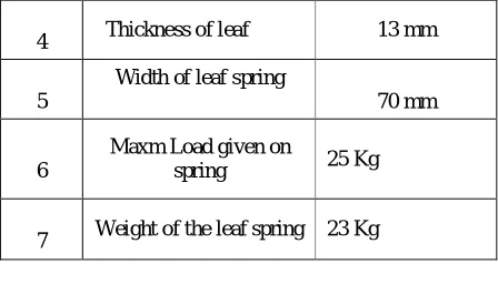
B. Dimensions of Composite Leaf Spring
Table no. 2 Design Parameter for composite leaf spring
Sr. No. Parameters Dimensions in
(mm)
1
Total Length of the
spring (Eye to Eye) 1540 mm
2
Free Camber (At no load
condition) 136 mm
3
No. of full length leave
(Master Leaf) 01
4 Thickness of leaf 13 mm
5
Width of leaf spring
70 mm
6
Maxm Load given on
spring 25 Kg
7 Weight of the leaf spring 23 Kg
IV. DESIGN OF STEEL MONO-LEAF SPRING
A. Materials of leaf springs
The material used for leaf spring is usually a plain carbon steel having 0.90 to 1.0% carbon. The leaves are heat treated after the forming process. The heat treatment of spring steel produces greater strength and therefore greater load capacity, greater range of deflection and better fatigue properties.
According to Indian standards, the recommended materials are:
1. For automobiles : 50 Cr 1, 50 Cr 1 V 23, and 55 Si 2 Mn 90 all used in hardened and tempered state.
2. For rail road springs: C 55 (water-hardened), C 75 (oil-hardened), 40 Si 2 Mn 90 (water-hardened) and 55 Si 2 Mn 90 (oil-hardened).
3. The physical properties of some of these materials are given in the following table. All values are for oil quenched condition and for single heat only.
The test steel leaf spring used for experiment is made up of 60Si7. The composition of material is 0.56 C%, 1.80 SI%, 0.70 Mn%, 0.045 P%, 0.045 S%. Following are the parameters for the 60Si7
Table no. 3 Physical properties of materials commonly used
for leaf springs.
Material Condition Ultimate tensile strength (MPa) Tensile yield strength (MPa) Brinell hardness number
50 Cr 1 1680-2200 1540-1750 461-601
50 Cr 1 V 23
Hardened and Tempered
1900-2200 1680-1890 534-601
55 Si 2 Mn 90
1820-2060 1680-1920 534-601
ISSN: 2231-5381
http://www.ijettjournal.org
Page 66 V. THREE-DIMENSIONAL FINITE ELEMENTANALYSIS
CAD Modeling of any project is one of the most time consuming process. One cannot shoot directly from the form sketches to Finite Element Model. CAD Modeling is the base of any project. Finite Element software will consider shapes, whatever is made in CAD model. Although most of the CAD Modeling software have capabilities of analysis to some extent and most of Finite Element software have capabilities of generating a CAD model directly for the purpose of analysis, but their off domain capabilities are not sufficient for large and complicated models which include many typical shapes of the product. The model of the multi leaf spring structures also includes many complicated parts, which are difficult to make by any of other CAD modeling as well as Finite Element software.
Modeling is done using Pro-E (Wild Fire) 4.0 and Analysis is carried out by using ANSYS 13.0 software for better understanding. SOLID187 element is a higher order 3-D, 10-node element. SOLID187 has a quadratic displacement behavior and is well suited to modeling irregular meshes (such as those produced from various CAD/CAM systems). The element is defined by 10 nodes having three degrees of freedom at each node: translations in the nodal x, y, and z directions. The element has plasticity, hyperelasticity, creep, stress stiffening, large deflection, and large strain capabilities. It also has mixed formulation capability for simulating deformations of nearly incompressible elastoplastic materials, and fully incompressible hyperelastic materials. The MPC184 rigid link/beam element can be used to model a rigid constraint between two deformable bodies or as a rigid component used to transmit forces and moments in engineering applications. This element is well suited for linear, large rotation, and/or large strain nonlinear applications.
Also, analysis carried out for composite leaf spring with eyes and the results were compared with steel leaf spring with eye end. Figs. 5 to 14 represent FEA results for steel and mono composite leaf spring (Carbon Fiber/Epoxy). The load, deflection for Carbon Fiber/Epoxy and for steel were measured and plotted as shown in Figs. 5.1 and 5.
A. Von Mises Stress for Composite Material at load of 5 Kg, 10 Kg, 15Kg, 20 Kg & 25 Kg
Fig.1 Von Mises Stress at load of 5 Kg.
Fig.2 Von Mises Stress at load of 10 Kg.
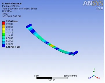
Fig. 3. Von Mises Stress at load of 15 Kg.
Fig.4 Von Mises Stress at load of 20 Kg.
International Journal of Engineering Trends and Technology (IJETT) – Volume 12 Number 2 - Jun 2014
ISSN: 2231-5381
http://www.ijettjournal.org
Page 67B Von Mises Stress for Steel Material at load of 5 Kg, 10 Kg, 15Kg, 20 Kg & 25 Kg
Fig. 6 Von Mises Stress at load of 5 Kg.
Fig. 7 Von Mises Stress at load of 10 Kg.
Fig. 8 Von Mises Stress at load of 15 Kg.
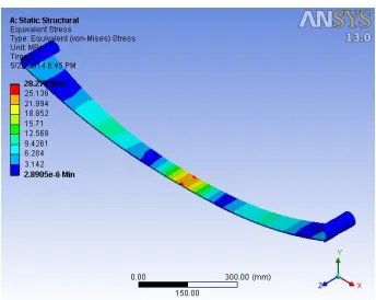
Fig.9 Von Mises Stress at load of 20 Kg.
Fig. 10 Von Mises Stress at load of 25 Kg.
C Load vs Deflection for Composite & Steel Mono Leaf Spring-
The load, deflection for steel as shown in Fig. 11
Fig. 11 The load, deflection curve for steel
The load, deflection for Carbon Fiber/Epoxy as shown in Fig. 12
Fig. 12 The load, deflection curve for composite.
0 1 2 3 4 5 6 7
0 10 20 30
0 1 2 3 4 5 6 7 8
ISSN: 2231-5381
http://www.ijettjournal.org
Page 68D. Load vs Deflection for Composite Mono Leaf Spring at load of 5 Kg, 10 Kg, 15Kg, 20 Kg & 25 Kg
Fig. 13 Load vs Deflection at load of 5 Kg.
Fig. 14 Load vs Deflection at load of 10 Kg.
Fig. 15 Load vs Deflection at load of 15 Kg.
Fig. 16 Load vs Deflection at load of 20 Kg.
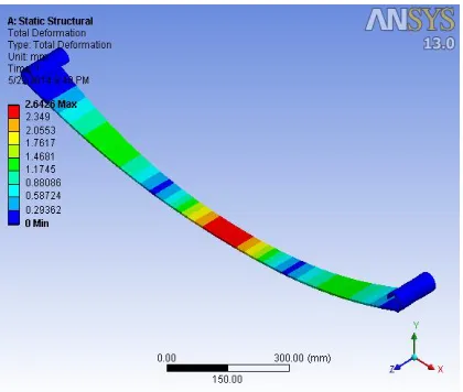
Fig. 17 Load vs Deflection at load of 25 Kg.
E Load vs Deflection for steel Mono Leaf Spring at load of 5 Kg, 10 Kg, 15Kg, 20 Kg & 25 Kg
-
International Journal of Engineering Trends and Technology (IJETT) – Volume 12 Number 2 - Jun 2014
ISSN: 2231-5381
http://www.ijettjournal.org
Page 69Fig. 19 Load vs Deflection at load of 10 Kg.
Fig. 20 Load vs Deflection at load of 15 Kg.
Fig. 21 Load vs Deflection at load of 20 Kg.
Fig.6.22 Load vs Deflection at load of 25 Kg.
VI. ANALYTICAL ANALYSIS OF LEAF SPRING
Leaf springs (also known as flat springs) are made out of flat plates. The advantage of leaf spring over helical spring is that the ends of the spring may be guided along a definite path as it deflects to act as a structural member in addition to energy absorbing device. Thus the leaf springs may carry lateral loads, brake torque, driving torque etc., in addition to shocks. Consider a single plate fixed at one end and loaded at the other end.
This plate may be used as a flat spring. Let
t = thickness of plate b = width of plate, and
L = length of plate or distance of the load W from the cantilever end, as shown in the Figure 1.
We know that the maximum bending moment at the cantilever end
M = W.L
And section modulus, Z =I/y
where I = (b.t3 / 12) and Y = t/2 So Z = b.t2 / 6
The bending stress in such a spring,
σb = M / Z = (6W.L) / b.t2 ……… .. (i)
We know that the maximum deflection for a cantilever with concentrated load at free end is given by
δ = W.L3 / 3.E.I = 2f.L2 / 3.E.t ………. (ii) It may be noted that due to bending moment, top fibers will be in tension and bottom fibers are in compression, but the shear stress is zero at the extreme fibers and the maximum at centre, hence for analysis, both stresses need not to be taken into account simultaneously. We shall consider bending stress only.If the spring is not of cantilever type but it is like a simply supported beam, with length 2L and load2W in the centre.
Maximum bending moment in the centre, M = W.L
ISSN: 2231-5381
http://www.ijettjournal.org
Page 70σb = 6W.L /b.t2
We know that maximum deflection of a simply supported beam loaded in the centre is given by
δ = W.L3 / 3.E.I
From above we see that a spring such as automobile spring (semi-elliptical spring) with length 2L and load in the centre by a load 2W may be treated as double cantilever. If the plate of cantilever is cut into a series
of n strips of width b and these are placed as shown in Figure 1, then equations (i) and (ii) may be written as
σb = 6W.L / n.b.t2 ……….. (iii)
δ = 4.W.L3 / n.E.b.t3 = 2. σb.L2 /3.E.t ……… (iv) The above relation gives the bending stress of a leaf spring of uniform cross- section and is given in
Table 1 at various loads. The stress at such a spring is maximum at support.
Analytical stresses and deflections of leaf spring can be calculated as
Analytical stress is calculated by
σb = 6 WL /n bt² Analytical deflection is given by
δ = ( 4 x W x L³ ) / ( n x E x b x t³ )
A. Calculation of Analytical Stresses for Steel
Analytical stress is calculated by σb = 6 WL /n bt²
1. For 2W= 25 Kg, W=12.5 Kg=12.5x 9.81= 122.62 N, 2L=1540 mm, L= 770 mm,
t= 13 mm & b=70 mm, n=1
σb=6x122.62x770/(1x70x13^2) =47.88 N/mm2
Similarly,
2. for 2W=20 Kg, σb = 38.31 N/mm2 3. for 2W=15 Kg, σb = 28.73 N/mm2 4. for 2W=10 Kg, σb = 19.15 N/mm2 5. for 2W=5 Kg, σb = 9.57 N/mm2
B. Calculation of Analytical Deflection for Steel
Analytical deflection is given by
δ = ( 4 x W x L³ ) / ( n x E x b x t³ )
1. For 2W= 25 Kg, W=12.5 Kg=12.5x 9.81= 122.62
N, E=22426.09x 9.81 N/mm2
δ = (4 x 122.62x770^3 ) / ( 1x 22426.09x9.81 x 70 x 13^2 )
= 6.618 mm Similarly
2. for 2W=20 Kg, δ = 5.294 mm 3. for 2W=15 Kg, δ = 3.970 mm 4. for 2W=10 Kg, δ = 2.647 mm 5. for 2W=5 Kg, δ = 1.323 mm
VII. RESULT AND DISCUSSION
The objective of this study is to evaluate the applicability of a composite leaf spring over conventional leaf spring in automobiles by reducing bending stresses with considering cost-effectiveness, riding comfort and strength. The comparison between multi-leaf spring and mono-leaf composite spring is made for the same requirements and loading conditions. The comparison is based on four major aspects such as stresses, deflection, weight, riding comfort & cost
A. Comparision in Stresses & Deflection for Composite & Steel Leaf Spring
Table No. 4 Comparision in Analytical & FEA Stresses for Steel Leaf Spring
Static analysis is performed to find the Von-Mises stress by using ansys software and these results are compared with bending stresses calculated in mathematical analysis at various loads.
The maximum stress values by analytical & FEA for the different load listed in Table no. 8.1 , which shows comparision between analytical & FEA stresses for conventional steel leaf spring & percentage deviation from analytical values.
Sr.
No. Wt.
Conventional Steel leaf
spring
Compos ite Leaf
Spring % Deviatio
n Deflection,
mm, Analytical
Deflecti on,FEA
1. 25Kg 6.618 7.108 7.40
2. 20Kg 5.294 5.785 9.27
3. 15Kg 3.970 4.163 4.86
4. 10Kg 2.647 2.842 7.36
International Journal of Engineering Trends and Technology (IJETT) – Volume 12 Number 2 - Jun 2014
ISSN: 2231-5381
http://www.ijettjournal.org
Page 71
Table No. 5 Comparision in Analytical & FEA deflection for Steel Leaf Spring
The maximum deflection values by analytical & FEA for the different load listed in Table no. 8.1 , which shows comparision between analytical & FEA deflection for conventional steel leaf spring & percentage deviation from analytical values.
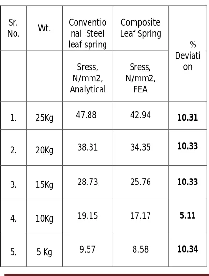
Table No.6 Comparision in Analytical Stress for Steel Leaf Spring & FEA stress composite leaf spring
The maximum stress values by analytical & FEA for the different load listed in Table no. 8.1 , which shows comparision between analytical stress values for conventional steel leaf spring & FEA stresses for composite leaf spring & percentage deviation from analytical values.
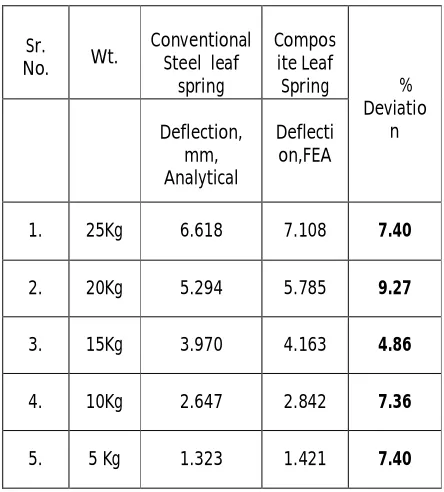
Table No. 7 Comparision in Analytical deflection for Steel Leaf Spring & FEA deflection composite leaf spring
The maximum deflection values by analytical & FEA for the different load listed in Table no. 8.1 , which shows comparision between analytical deflection values for conventional steel leaf spring & FEA deflection for composite leaf spring & percentage deviation from analytical values
B. Stesses Comparison in Steel & Composite Material-
It is seen from the graph & table given below,for the same load the stresses generated in the composite material are less as compared to the stresses produced in the steel material. So it is useful when the steel material are replaced by the composite material & also there is more than 80% weight reduction is present. It is seen that from the graph that when load increases the bending stress increases linearly. So load-stress graph gives the straight line relationship. At lower loads both theoretical and ANSYS results are very close, but when load increases the ANSYS results are uniformly reduced compared to theoretical results.The deflection in steel leaf spring is more as compared to the composite leaf spring as shown in the above graphs & it will also from the above table. Sr.
No. Wt.
Conventional Steel leaf spring
Sress, N/mm2, Analytical
Stress FEA, N/mm2
% Deviation
1. 25Kg 47.88 47.13 1.56
2. 20Kg 38.31 37.78 1.38
3. 15Kg 28.73 28.27 1.60
4. 10Kg 19.15 18.85 1.56
5. 5 Kg 9.57 9.42 1.56
Sr.
No. Wt.
Conventio nal Steel leaf spring
Composite Leaf Spring
% Deviati
on Sress,
N/mm2, Analytical
Sress, N/mm2,
FEA
1. 25Kg 47.88 42.94 10.31
2. 20Kg 38.31 34.35 10.33
3. 15Kg 28.73 25.76 10.33
4. 10Kg 19.15 17.17 5.11
5. 5 Kg 9.57 8.58 10.34
Sr.
No. Wt.
Conventional Steel leaf spring
Deflection, mm, Analytical
Deflectio n, FEA
% Deviati on
1. 25Kg 6.618 6.606 0.18
2. 20Kg 5.294 5.285 0.17
3. 15Kg 3.970 3.963 0.17
4. 10Kg 2.647 2.642 0.18
ISSN: 2231-5381
http://www.ijettjournal.org
Page 72 Table No. 8 Comparision in Stresses for Composite &Steel Leaf Spring
Sr . N o.
Load,
Kg Stresses
in Steel, , N/mm2
Stresses in Compos
ite Materia
l, N/mm2
Stress values in Composi te is reduced by, N/mm2
1 25 47.88 42.94 4.94
2 20 38.31 34.35 3.96
3 15 28.73 25.76 2.97
4 10 19.15 17.17 1.98
5 5 9.57 8.58 0.99
Fig. 23 Stresses for Steel vs. Composites
C. Deflection Comparison in Steel & Composite Material-
It is seen from the table & graph given below, the composite material leaf spring is deflect more as compared to the steel leaf spring, so that composite material leaf spring lower the spring rate as compared to the steel leaf spring. Spring rate is amount of weight required to deflect a spring one inch. The lower the spring rate , softer the spring. Therefore, smoother thre ride. Hence the riding comfort of an automobile is increased due to the replacement of the steel leaf spring by composite leaf spring. No one to the best of knowledge has worked but qualitatively on how much improvement in mileage/lit of passenger vehicle occurs and how much riding comfort improves. Only qualitative information is available on riding comfort of vehicle with respect to its unsprung mass
Table No. 9 Comparision in deflection for Composite & Steel Leaf Spring
S r. N o .
Loa d, Kg
Defl. in Stee
l, , mm
Defl. in Com.
mtl, mm
Defl. values in
Composite is increased by, mm
1 25 6.618 7.108 0.49
2 20 5.294 5.785 0.491
3 15 3.970 4.163 0.193
4 10 2.647 2.842 0.195
5 5 1.323 1.421 0.098
Fig. 24 Deflection for Steel vs. Composites
C. Comparison of Rigidity Qualities
The weight reduction of unsprung mass of an automobile will improve the riding quality. The suspension leaf contributes 10% - 20% of the unsprung mass. The weight of the composite leaf spring is 3.75 times less than steel leaf spring. Hence the riding comfort of an automobile is increased due to the replacement of the steel leaf spring by composite leaf spring. No one to the best of knowledge has worked but qualitatively on how much improvement in mileage/lit of passenger vehicle occurs and how much riding comfort improves. Only qualitative information is available on riding comfort of vehicle with respect to its unsprung mass.
E. Cost Comparison
The cost estimation of composite leaf spring provides a clear economic viability of the product in comparison to that of a convectional leaf spring.
0 10 20 30 40 50 60
1 2 3 4 5
Steel
Composite
0 1 2 3 4 5 6 7 8
1 2 3 4 5 6 7 8 9 10
Composite
International Journal of Engineering Trends and Technology (IJETT) – Volume 12 Number 2 - Jun 2014
ISSN: 2231-5381
http://www.ijettjournal.org
Page 73VIII. CONCLUSIONS & FUTURE SCOPE
A .Conclusions
It is observed that from table no. 8.3, analytical results & finite elemnt results of bending stresses for conventional steel leaf spring are compared with composite leaf spring & there is found fairly good agreement between these analysis.
From table no. 8.5, it has been noticed that bending stresses in composite material is reduced as compared to conventional steel leaf spring & it is visible from last coloumn of table i.e. upto 10.34 % reduction observed in bending stresses which is desirable for leaf spring of vehicle.
From table no. 8.5, it has been noticed that , the composite material leaf spring is deflect more as compared to the steel leaf spring i.e upto 9.27 % more, so that composite material leaf spring lower the spring rate as compared to the steel leaf spring. Spring rate is amount of weight required to deflect a spring one inch. The lower the spring rate , softer the spring. Therefore, smoother thre ride.
Since, the composite leaf spring is able to with stand the static load as well as the fatigue load, it is concluded that there is no objection from strength point of view also, in the process of replacing convectional leaf spring by composite leaf spring. It is seen that from the graph that when load increases the bending stress increases linearly. So load-stress graph gives the straight line relationship. At lower loads both theoretical and ANSYS results are very close, but when load increases the ANSYS results are uniformly reduced compared to theoretical results.It is seen from the table & graph given below, the composite material leaf spring is deflect more as compared to the steel leaf spring, so that composite material leaf spring lower the spring rate as compared to the steel leaf spring. The lower the spring rate , softer the spring. Therefore, smoother thre ride & also less bending stresses are generated in composite leaf spring. The major disadvantage of composite leaf springs is cost and resistance. In this study, the cost factor has been proved to be ineffective. However the matrix material is likely to chip off when it is subjected to poor road environment (i.e. if some stone hit the composite leaf spring then it may produce chipping), which may sometimes break the fibers in the lower portion of the spring. This may result in a loss of capability to share flexural stiffness. But this depends on the condition of the road. In normal road condition, this type of problems will not occur.
B. Future scope:
After carrying out the present work, it is found that the following things can be added as an extension to this work-
As analysis of composite leaf spring & steel leaf spring is validated by the analytical results, so one can validate with manufacturing of actual prototype of composite & steel leaf spring by testing on universal testing machine(UTM)
As this analysis is under static load condition, so one can go for the analysis of composite & steel leaf spring under dynamic loading condition.REFERENCES
[[1] Senthil kumar and Vijayarangan, “Analytical and Experimental studies on Fatigue life Prediction of steel leaf soringand composite leaf multi leaf spring for Light passanger veicles using life data analysis” ISSN 1392 1320 material science Vol. 13 No.2 2007.
[2] Shiva Shankar and Vijayarangan “Mono Composite Leaf Spring for Light Weight Vehicle Design, End Joint, Analysis and Testing” ISSN 1392 Material Science Vol. 12, No.3, 2006.
[3] Niklas Philipson and Modelan AB “Leaf spring modelling” ideon Science Park SE-22370 Lund, Sweden
[4] Zhi’an Yang and et al “Cyclic Creep and Cyclic Deformation of High-Strength Spring Steels and the Evaluation of the Sag Effect:Part I. Cyclic Plastic Deformation Behavior” Material and Material Transaction A Vol 32A, July 2001—1697
[5] Muhammad Ashiqur Rahman and et al “Inelastic deformations of stainless steel leaf springs-experiment and nonlinear analysis” Meccanica Springer Science Business Media B.V. 2009
[6] C.K. Clarke and G.E. Borowski “Evaluation of Leaf Spring Failure” ASM International, Journal of Failure Analysis and Prevention, Vol5 (6) Pg. No.(54-63)
[7] J.J. Fuentes and et al “Premature Fracture in Automobile Leaf Springs” Journal of Science Direct, Engineering Failure Analysis Vol. 16 (2009) Pg. No. 648-655.
[8] J.P. Hou and et al “Evolution Of The Eye End Design Of A Composite Leaf Spring For Heavy Axle Load ” Journal of Science Direct, Composite Structures 78(2007) Pg. No. (351-358)
[9] Gulur Siddaramanna SHIVA SHANKAR, Sambagam
VIJAYARANGAN, “Mono composite leaf spring for light weight
vehicle-Design End joint analysis and testing”, ISSN 1392-1320
MATERIALS SCIENCE (MEDZIAGOTYRA). Vol. 12, No.3. 2006. [10] “Theory of Machines”,R.S. Khurmi, J.K. Guptta, S. Chand Publications,14th edition, 2010.
[11] Mouleeswaran SENTHIL KUMAR, Sabapathy VIJAYRANGAN,
“Analytical and Experimental studies on Fatigue Life prediction of Steel and Composite Multi-leaf for Light Passenger Vehicles Using life data analysis”,
ISSN 1392-1320 MATERIALS SCIENCE (MEDZIAGOTYRA). Vol. 13, No. 2. 2007.
[12] SAE, “Manual on Design and Application of Leaf Springs”,SAE HS 788, Society of Automotive Engineers, Warrendale, PA, 1980.
[13] Al-Qureshi, H.A., “Automobile leaf springs from composite materials”, Journal of Materials Processing Technology, 118(1-3):pp.58-61. [doi:10.1016/S0924-0136(01) 00863-9]
[14] Mahdi, E., Alkoles, O.M.S., Hamouda, A.M.S., Sahari, B.B., Yonus, R., Goudah, G., “Light composite elliptic springs for vehicle suspension”,
Composite Structures, 75(1-4): pp.24-28.
[doi:10.1016/j.compstruct.2006.04.082]
[15] Reaz A. Chaudhuri , K. Balaraman “A novel method for fabrication of fiber reinforced plastic plates” Composite Structures 77 (2007), pp.160-170.
[16] Practical Finite Element Analysis by Nitin S. Gokhale [17] Composites – A Design Guide by Terry Richardson [18] ANSYS 10.0 Help for FEA Analysis
[19] Text book of Machine Design by R.S. Khurmi and J.K. Gupta [20] Introduction to Steel Reference Books S. N. Bagchi and Kuldeep Prakash
[21] Spring Designers Hand Book by Carlson