NETWORKING ELEMENTS
Thesis by Chenggong Charles Fan
In partial fulfillment of the requirements
for the degree of
Doctor of Philosophy
California Institute of Technology
Pasadena, California
2001
Chenggong Charles Fan
ACKNOWLEDGMENTS
First of all, I would like to thank my advisor, Professor Shuki Bruck. His vision and guidance made this work happen. I would also like to express my gratitude to the other professors at Caltech, for you not only directly or indirectly helped my graduate studies, but also made Caltech a great place to be. The friends from the Paradise research lab and other labs helped make my Caltech years so enjoyable, that I don’t mind being a graduate student for longer. My colleagues at Rainfinity made valuable contributions to some of the results in this dissertation. To them I say thank you.
ABSTRACT
The explosive growth of the Internet demands higher reliability and performance than what the current networking infrastructure can provide. This dissertation explores novel
architectures and protocols that provide a methodology for grouping together multiple networking elements, such as routers, gateways, and switches, to create a more reliable and performant distributed networking system. Clustering of networking elements is a novel concept that requires the invention of distributed computing protocols that facilitate efficient and robust support of networking protocols. We introduce the Raincore protocol architecture that achieves these goals by bridging the fields of computer networks and distributed systems.
In designing Raincore, we paid special attention to the unique requirements from the networking environment. First, networking clusters need to scale up the networking throughput in addition to the scaling up of computing power. Second, task switching between the different services supported by a networking element has a major negative impact on performance. Third, fast fail-over time is critical for maintaining network connections in the event of failures. We discuss in depth the design of Raincore Group Communication Manager that addresses the forgoing requirements and provides group membership management and reliable multicast transport. It is based on a novel token-ring protocol. We prove that this protocol is formally correct, namely, it satisfies the set of formal specifications that defines the Group Membership problem.
spin-off company, that provides the first fault-tolerant and scalable firewall cluster. These applications exhibit the fast fail-over response, low overhead, and near-linear scalability of the Raincore protocols.
TABLE OF CONTENTS
1 Introduction...1
1.1 Reliability and Performance of Networking Elements...3
1.2 Contributions of this Dissertation ...6
2 Background on Computer Networks and Distributed Systems...10
2.1 What is a Computer Network? ...11
2.2 What is a Distributed System?...23
3 Raincore Architecture and Protocols...34
3.1 Architecture...34
3.2 Transport Manager...36
3.3 Group Communication Manager...38
3.4 Group Membership Specifications ...38
3.5 Group Membership Protocol...42
3.6 Correctness Proof...54
3.7 Extensions...58
3.8 Reliable Multicast...62
3.9 Mutual Exclusion...64
3.10 Group Data Manager...65
4 Raincore Applications and Performance...67
4.1 SNOW...67
4.2 CLOUD...68
4.3 RainWall...71
4.4 RainFront Platform...74
4.5 Overhead Analysis ...77
4.6 Performance Benchmark...80
5 Fault-Tolerant Multistage Interconnection Networks...84
5.1 An Optimal Construction ...92
5.2 Necessary and Sufficient Condition...96
5.3 Extensions...99
6 Conclusion and Future Directions...103
LIST OF FIGURES
Figure 1 A traffic path between a client and a server farm 3 Figure 2 The ten-node RAIN cluster in Paradise Lab, Caltech 10
Figure 3 The OSI seven layer reference model 15
Figure 4 Path of a packet 21
Figure 5 Raincore distributed services architecture 34
Figure 6 Token message format 43
Figure 7 The 911 message format 43
Figure 8 Local data structures on each node 44
Figure 9 View State transition diagram 45
Figure 10 Token State transition diagram 46
Figure 11 Overall state transition diagram 49
Figure 12 Example of token-ring protocol without failures 53 Figure 13 Example of token-ring protocol with a node failure 53 Figure 14 Example of token-ring protocol with a node recovery 54
Figure 15 Link failure scenario 59
Figure 16 Six-node SNOW cluster 67
Figure 17 A cluster of CLOUD nodes with two pools of Virtual IPs. 69
Figure 18 RainWall Graphical User Interface 73
Figure 19 RainFront platform architecture 74
Figure 20 RainFront Graphical User Interface 76
Figure 21 RainWall performance benchmark 81
Figure 22 Two-node Raincore Windows NT benchmark 83 Figure 23 Operation models of a 2 X 2 switching element 85 Figure 24 A three-dimensional MIN using 2X2 switches 87 Figure 25 Three-dimensional one-extra-stage Extra Stage Cube MIN 89 Figure 26 Three-dimensional one-extra-stage Cyclic MIN 90 Figure 27 Three-dimensional four-extra-stage Cyclic MIN 93
Figure 28 Construction of f+1 disjoint paths 94
1 INTRODUCTION
We live in an age of information. The science of information has evolved dramatically in the last century. Scientists discovered fundamental truths about the bits and the bytes, and made great progress in the areas of computation, communication, and storage. Computation is the creation and the manipulation of information; communication is the transportation of information; and storage is the placement of the information. Around these three arms of the information science emerged the computer industry and the networking industry.
The advent of the Internet is changing the way that people manage and access information. In the last five years, the amount of traffic on the Internet has been growing at an exponential rate. The World Wide Web has evolved from a hobbyists’ toy to become one of the
dominating media of our society. E-Commerce has grown past adolescence and multimedia content has come of age. Looking forward, this growth will continue for some time. There are four general trends in the growth of the Internet:
First, Internet clients are becoming more numerous and varied. In addition to the ever-increasing number of PCs in offices and homes, there are new types of clients, such as mobile data units (cell phones, PDAs, etc.) and home internet appliances (set-top boxes, game consoles, etc.). In the future not too far away, these new types of Internet devices will pervade the Internet landscape.
Second, to support these new clients, new types of networks are being designed and
networks. Technologies are being developed to connect these new networks with the existing Internet backbone.
Third, the content delivered over the Internet is evolving, because of the emergence of the new clients and new networks. There will be a growing presence of multimedia content, such as video, voice, music and gaming streams. The growth in content adds not only to the volume of the traffic, but also to the computation complexity in transporting and processing the traffic, thus accelerating the convergence between communication and computation.
Lastly, because of the abovementioned growth, new Internet applications will emerge, both on the server side and the client side. As the Internet penetrates deeper and deeper into everyone’s life, the demand for security, reliability, convenience, and performance skyrockets. With the popularity of cars comes the invention of traffic lights and stop signs, the gas station and the drive-thru. As Internet makes its way into daily lives, the demand will grow for firewalls and VPNs, intrusion detection and virus scanning, server load balancing and content management, quality of service and billing/reporting applications. The list goes on and will keep expanding.
1.1 Reliability and Performance of Networking Elements
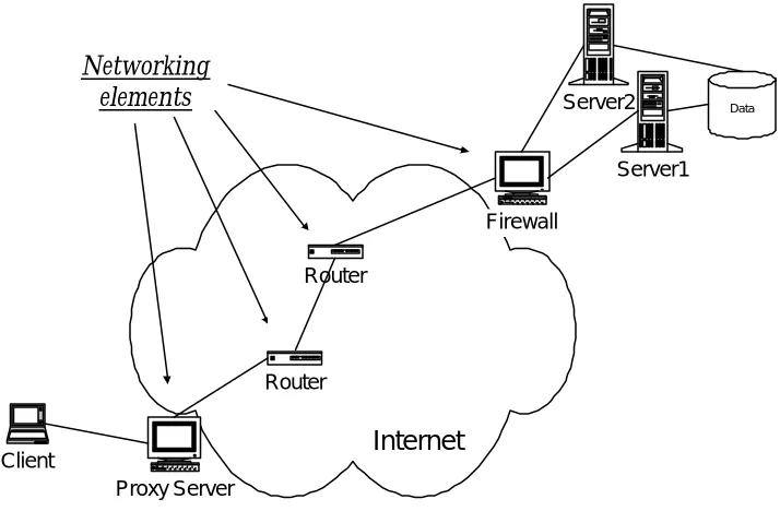
The primary function of the Internet is for information to flow from where it is stored to where it is requested. The Internet is the network that interconnects all clients and servers to allow information to flow in an orderly way. The communication path between a client and a server can be viewed as a chain. Each networking device along the path between the client and the server is a link in the chain. Figure 1 illustrates a n example of a traffic path between a client and a server farm in the Internet.
Client
Server1
Data
Router Router
Proxy Server
Firewall
Server2
Internet Networking
[image:10.612.143.500.283.517.2]elements
Figure 1 A traffic path between a client and a server farm
The key to reliability is redundancy. If one device fails, there must be a second device ready and able to take its place. If the second device fails, there must be a third one, and so on. The key to performance is processing power. To increase capacity and speed, the customer has a choice of using a bigger, faster processor, or by dividing the task among several processors working in concert. Using a single processor limits scalability to the state of the art in processors, so that performance can only be what Moore’s Law will allow. Multiple processors working in a cluster provide a more flexible and scalable architecture. Capacity can be added or subtracted at will; the overall performance to price ratio is higher; and combined with intelligent fail-over protocols, such a cluster enables higher reliability.
A chain is only as strong as its weakest link, and the longer the chain, the weaker it is overall. To increase reliability and performance, one should look for ways to reduce the number of links in the chain and make each remaining link more robust. The weak links in the Internet infrastructure are single points of failure and performance bottlenecks. Single points of failure are devices that have no inherent redundancy or backup. Bottlenecks are devices that do not have enough processing power to handle the amount of traffic they receive.
Currently there are solutions that address both the reliability and the performance problem in the networking world. The most popular solution is typically referred to as the hot standby solution. In this solution, a secondary device is setup to be identical to the primary device. When the primary device fails, the secondary device detects it, and activates itself to perform the function of primary device. This is a very practical solution to address the single point of failure problem. However it does not increase the performance of the primary device, and therefore does not address the performance problem.
bottleneck, more devices can be setup to perform the same function, and external load balancers can be set up at each of the subnet these devices connect to. The load balancers are capable both of balancing the load to these devices, as well as detecting the failures among these devices, therefore address both the reliability and performance problem. However there are limitations to this approach. Load balancers become additional links to the chain and can become points of failures and performance bottlenecks themselves and load balancers can not share application state among the devices.
We propose to increase the reliability and performance of the Internet by clustering the networking elements. This is using the concept of building a larger system by using multiple smaller units, to improve overall system performance and reliability. In the chain of links analogy, it is equivalent to strengthening one link without adding additional links. In some cases, it may even allow several links to be consolidated into one. By having multiple networking elements work together for the same purpose, this in effect creates a distributed system in a networking environment. For example, in Figure 1, instead of having one firewall front-gate the server farm, a cluster of firewalls can be used. The objective of this distributed system is to enable both load balancing and fail-over among the member nodes. To load balance, there must be a way to distribute network traffic to members of the cluster, so that the overall throughput is multiplied. To fail over, the healthy nodes must discover nodes that have failed, and take over the networking traffic from the failed node without interrupting the traffic flow.
seven-layer model. Great strides are being made in optical communication at the bottom layer of the communication stack, the Physical layer. In the last fifteen years, Ethernet has become the backbone at the data link layer (Layer 2) for local area networking. It not only permeates every office, but also enters more and more homes. The TCP/IP protocol suite is widely adopted around the world and has become the de facto standard for Network Layer (Layer-three) and Transport Layer (Layer-4). Meanwhile, trillions of bits of information are being communicated over the Internet using Session Layer (Layer-5), Presentation Layer (Layer-6), and application layer (Layer-7) protocols, such as HTTP and FTP.
At the same time, results from the field of parallel and distributed computing have enabled the making of supercomputers and other powerful computing systems. They push the frontier of scientific discovery by providing more computation power than ever thought possible. Their contributions range from depicting the history of our universe to helping prove open
mathematical problems. Parallel and distributed computing technologies are also widely used in the business world for data processing and storage.
1.2 Contributions of this Dissertation
those goals in a way that complies with the existing networking protocols, and do that in the most efficient and least intrusive way?
The bulk of this thesis is devoted to the presentation of Raincore, a suite of distributed protocols for networking devices that try to answer the questions above [Fan and Bruck, 2001]. Raincore is a collection of protocols that provides reliable unicast, reliable multicast, group membership, state sharing, mutual exclusion, and resource allocation services. The Raincore protocols and services are designed to achieve the best performance in a networking
environment, and are applicable to a wide range of networking devices, from layer-three devices, such as routers, to layer-7 devices, such as firewalls and proxy servers. Raincore provides fast failure recovery and near-linear throughput scaling, as demonstrated by a number of networking applications that have been built using it.
A distributed system allows multiple machines to work together as if they were a single system. The key challenge here is that all the machines in the cluster need to have consensus on the exact state of the cluster and make collective decisions without conflicts. To address the issue of reliability, a distributed system must also allow healthy machines within the cluster to automatically and transparently take over for any failed nodes. To address the issue of performance, all healthy nodes in the cluster must be actively processing in parallel, and each additional node must add processing power to the group, not detract from it. Creating such a solution for the Internet infrastructure is an exciting, but difficult task.
can coexist with Raincore on the same group of physical computers. This reduces the number of links in this Internet chain, and therefore improves the overall reliability and performance of the Internet.
In this dissertation, after presenting the introductory background on the existing results in computer networks and distributed systems in Chapter 2, we’ll introduce the architecture and the key protocols in Raincore Distributed Services in Chapter 3. We will introduce the Raincore protocols and services in the Transport Layer, Session Layer, and Presentation Layer of the networking stack. The focus will be on the Group Communication Manager, which situates in the Session Layer, and provides group membership management, reliable multicast, and mutual exclusion services for the nodes in a cluster. We’ll prove that the Raincore group membership protocol meets one specification of the Group Membership Problem.
broadcast-based group communication protocols and present the performance benchmarks of some of the Raincore applications.
Also included in this thesis are the interesting results on the optimal constructions for fault-tolerant Multistage Interconnection Networks [Fan and Bruck, 1997]; [Fan and Bruck, 2000]. Multistage Interconnection Networks is a distributed system that serves as a larger Layer-2 switch by grouping a number of smaller switches (typically 2 X 2 switches) together. It has the benefit of overall cost saving and built-in fault-tolerant capabilities. We discovered a family of construction that requires the least number of extra components to tolerate multiple
component failures. We also proved that our family of constructions is the only family that has this property. In Chapter 5, we present the results on the fault-tolerant constructions on Multistage Interconnection Networks that use the minimal number of extra stages to tolerate multiple switch faults.
2 BACKGROUND ON COMPUTER NETWORKS AND DISTRIBUTED
SYSTEMS
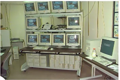
[image:17.612.107.491.349.605.2]The work on Raincore suite of protocols and services started as a part of the RAIN research project [Bohossian et al. 2001]. RAIN stands for Reliable Array of Independent Nodes. The goal of the project is to bridge between networking protocols and distributed systems. During this project, we created reliable and high-performance distributed systems by clustering commercial off-the-shelf hardware using fault-tolerant software. Figure 2 shows a 10-node RAIN cluster constructed in the Parallel and Distributed Systems Lab in Caltech.
Figure 2 The ten-node RAIN cluster in Paradise Lab, Caltech
stack. These protocols and services work together to enable the clustering of networking elements in that environment. In particular, the networking elements that we paid special attention to are the routers and their variants. Therefore comes the name “Raincore”. It stands for “RAIN Cluster Of Routing Elements”.
Part of the motivation for the Raincore is the wide gap between the state-of-the-art research in distributed systems in academia and the primitive high-availability solutions deployed in the Internet industry today. Most of the high-availability solutions that can be found in the Computer Networking industry are standby solutions. In a standby solution, a secondary idle node is present to monitor the primary node, and becomes active if the primary node fails. Being a useful high-availability solution, this solution does not take advantage of the processing power of the secondary node and offers no scalability. Raincore is designed to bridge this gap, to create a true distributed system for networking devices, so that multiple networking devices can work together to achieve combined performance and superior reliability.
Before digging into the details of the Raincore Architecture and Raincore protocols, we would like to introduce the background of the field of computer networks and the field of distributed systems.
2.1 What is a Computer Network?
computer and increasing its computation power. According to the famous Moore’s Law, the computation power of the state-of-the-art computer chip doubles every 20 months. Indeed, in the last thirty years, the reality closely followed Dr. Moore’s prediction.
What is a network? By definition, it is a group or system whose members are connected in some way. Since the beginning of the human history, we have been living in a network. The human society itself is a network that’s interconnected by human relationships. We built irrigation networks to increase the farm production; we built transportation networks that linked the towns and the cities of the world; we built the power network that delivered electricity to every home; we built the telephone network so that everyone else in the world is but a few dials away.
What is a computer network? According to Andrew Tannenbaum in his classic namesake book, “a computer network is an interconnected collection of autonomous computers” [Tannenbaum, 1996]. Computer industry is a young industry. During the first twenty years of its existence, there was no need for a computer network. The industry was dominated by the mainframe computers. The basic functions of a computer are the computation and storage of information, and it is obvious why people need to interconnect the computers together. In a medium-size company or university there might have been one or two computers, sitting in a centralized computer center. People who need to use it would come to the computer center, enter the instructions and the data, and out come the results.
network is born. The simple act of connecting the computers together immediately revolutionized the way the business was done.
Client-server becomes a dominating model of operation in most of the modern companies. In a client-server model, the clients are the PCs that sit on each user’s desk. The clients serve as an access point to the information, and perform most of the computation on the data. The data, however, is stored on the servers. With this model, the clients perform all user-specific tasks, while the servers handle all the tasks that need to be shared among the users. This allows for both the scalability of computation power and the resource sharing among the users. The first servers in an enterprise world are file servers, which simply stored the bits and bytes of a data file. Gradually, more sophisticated servers are produced and being relied upon. Examples include both the indispensable database servers for an enterprise and ubiquitous web servers on the Internet. Although each of them works in somewhat different ways, the one thing in common is that they hold the data that multiple clients need to share.
In addition to efficient resource sharing, a computer network also provides a powerful communication medium among people. After the postal mail, telegraph, telephone and fax, email is the new mainstream way for interpersonal communication. The Internet and the World Wide Web are great manifestations of the computer networks that linked the world together. Some of the old communication medium is being converted to go over the Internet. We have already seen fax and telephone over the Internet. We will also see more and more video conferencing, as well as meeting and collaboration over the web. In short, the advances in computer networks have been and will continue to reshape the lives of everyone.
point-to-point network, each message can only have one member of the network as its source, and one member of the network as its destination. The other members of the network, who are neither the source nor the destination, will not be able to see the message. In contrast, in a Broadcast Network, all members of the network will be able to see all messages. They will simply ignore the messages which are not addressed to them.
Another way of categorizing the computer networks is by looking at the distance among the members of the network. There are generally two big classes of networks: LAN (Local Area Networks) and WAN (Wide Area Networks). Local Area Networks usually span within a single campus of up to a few miles in size. Because they situate close to each other, in general we can expect high bandwidth and low latency from any member to any member in a LAN environment. In contrast, Wide Area Networks connect members thousands of miles apart. WAN usually uses point-to-point networking technologies while LAN uses the broadcast ones. The divisions nowadays between WAN and LAN, however, are not clear-cut. There are MANs (Metropolitan Area Networks), which are networks that span larger areas than LANs, but still use a broadcast medium to connect its members. There are also special LANs that are geographically distributed, but connected with private high performance links. This is popular with the bigger enterprises for connecting their major offices in different cities in the world.
2.1.1 The Network Protocol Stack
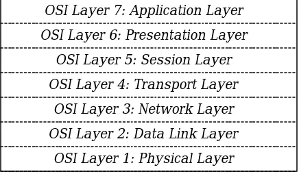
Zimmermann, 1983]. This model is popularly referred to as the OSI (Open Systems Interconnection) Reference Model (Figure 3). Almost all modern computer network protocols can be categorized with this reference model.
OSI Layer 7: Application Layer OSI Layer 6: Presentation Layer
OSI Layer 5: Session Layer OSI Layer 4: Transport Layer
OSI Layer 3: Network Layer OSI Layer 2: Data Link Layer
[image:22.612.109.327.175.302.2]OSI Layer 1: Physical Layer
Figure 3 The OSI seven layer reference model
Physical layer is the bottom-most layer that deals with how information is being transmitted over different physical medium. Currently the predominant physical mediums are copper wires and fiber optics. Typically, electrical or optical waveforms are being generated corresponding to the bits and bytes of information that needs to be transmitted. The physical medium by nature is analog, while the information is typically discrete. The physical layer protocols determine how the conversion should happen.
Physical layer only has the knowledge of how to transmit a bit of information from A to B. It has no idea which bit is the beginning of a transmission, which bit is the end of the
The key concept in the data link layer is the concept of a frame. This is a block of data that is transmitted logically in an atomic way. Most data link layer protocols are capable of resending lost frames by the use of acknowledgement frames. Some protocols even have the capability of dealing with damaged frames and duplicated frames. A special sub-layer of the data link layer, the MAC (Medium Access Layer) layer, also determines how to control access to a shared broadcast channel. This is particularly important for a Local Area Network. The most popular data link layer protocol in a LAN environment is IEEE 802.3, also known as the Ethernet. It uses a version of a MAC protocol called CSMA/CD (Carrier Sense Multiple Access with Collision Detection) [Kleinrock and Tobagi, 1975]. Other important Data Link protocols include IEEE 802.4 (Token Bus), IEEE 802.5 (Token Ring), and IEEE 802.6 (Distributed Queue Dual Bus).
There are many millions of computers in the world that are connected directly or indirectly to the biggest computer network, the Internet. It is impossible for every computer to have a direct connection to all of the other computers. Therefore, we need the concept of a subnet
(sub-network.) A computer network often is consisted of a number of subnets. A member of the subnet can send a network message directly to any other member in the same subnet. However, for a message to reach its destination in a different subnet, it needs to travel through intermediate stations, which are connected to multiple subnets. Such intermediate stations are commonly referred to as routers. The job of finding the right routers to route a message belongs to the network layer. The most popular network layer protocol today is IP, the Internet Protocol.
what needs to happen at these endpoints. The actions a transport layer protocol may take include splitting the message into smaller units at the source and reassemble them at the destination. It may multiplex multiple messages into one communication channel or create multiple channels for faster transport of a single message. It may also incorporate flow control algorithms that the receiver notifies the sender of its available buffer, so that the sender does not overwhelm the receiver. The transport protocols can range from very simple ones, such as UDP (User Datagram Protocol), to more sophisticated ones, such as TCP (Transport Control Protocol).
Layer 5 in the OSI model is the session layer. A session is a long-lasting data connection among members of the network that may also provide enhanced useful services. For example, SSL (Secure Socket Layer) protocol can be considered a session layer protocol. While it is not as well known as some of the other layers, as we will find out in Section 2.3, it is a very important layer for the Raincore architecture.
Similar to the session layer, the presentation layer is less referred to both in the networking industry and in the academic research. One of the main reasons for their anonymity is that the TCP/IP protocol suite largely ignored these two layers [Stevens, 1994]. The duty of this layer is to mask the actual movement of bits and bytes among different members of a
heterogeneous network transparent to the applications. Initially, things like the data serialization, character encoding, byte-order aligning of the data are typically functionalities in this layer. In this thesis, some very important protocols belong to this layer.
SMTP (Simple Mail Transfer Protocol) is designed for electronic mail delivery. DNS (Domain Name Service) maps host names onto their network addresses, while HTTP (Hypertext Transfer Protocol) is the backbone of the World Wide Web.
For a computer network to function well, a suite of network protocols is needed. Different protocols in the suite can be categorized into different layers according to the seven-layer reference model. The most popular protocol suite today, the TCP/IP protocol suite, was not exactly designed to conform to the seven-layer model. However, it can be easily referenced by the OSI model. Originally, TCP/IP gained its popularity because it was part of UNIX and what the Internet was built upon. In the 1990’s, along with the amazing growth of the Internet and the World Wide Web, TCP/IP reached everywhere, and is expected to be at even more places as the Internet reaches every wireless device and enters every home.
2.1.2 How does it work?
The protocols at different layers work together to generate, transfer, and process messages. Those messages are typically transmitted in the form of packets. As a packet travels down the network stack, each layer adds an additional header to the packet. Contained in the header are the administrative information important for that layer. As a packet travels up the stack, each layer parses the header for that layer, and strips the header away before sending to the upper layers.
The first thing that the web browser application does is invoking the DNS protocol to look up which IP address corresponds to the domain name caltech.edu. DNS tells the browser that the IP address of caltech.edu is 131.215.48.51. The browser therefore creates an HTTP request, asking for the homepage from 131.215.48.51. HTTP is an application layer protocol that uses TCP, the transport layer protocol. The TCP module on my computer (whose IP address, let’s say, is 66.27.171.182) tries to create a connection with the TCP module on 131.215.48.51.
Since the HTTP is not the only application module that uses the TCP module, TCP uses a 16-bit port number to identify the applications. The HTTP server uses a well-known port 80. The TCP module usually randomly picks a port for the HTTP client in the range between 1024 and 5000. In this case, let’s say, the port number for the HTTP client is 1372. This five-tuple of information {source IP address, source port number, protocol, destination IP address, destination port number} uniquely identifies a network connection. In this case, the TCP connection for the HTTP request is identified as {66.27.171.182, 1372, TCP, 131.215.48.51, 80}.
The TCP uses a three-way hand-shake protocol to establish a point-to-point connection, of which the first packet to send is a SYN packet. The TCP module on my computer, therefore, asks the IP module on my computer to send out the TCP SYN packet to 131.215.48.51, port 80. The IP module looks into its routing table to decide which router should this packet be delivered to in order to reach that destination. According to the routing table, router 66.27.171.254 is to be used.
subnetwork. My computer sends out an ARP request, asking who owns the IP address 66.27.171.254. The computer who owns this IP address would send an ARP reply with its Ethernet MAC address. This allows my computer to send out the Ethernet packets to 66.27.171.254, the first router on its way to the source of the information.
When 66.27.171.254 receives the packet, the IP layer sees that it is a packet destined to 131.215.48.51. It looks into its own routing table and forwards it to the next hop router. A message would typically travel through a number of routers before it reaches the final destination 131.215.48.51. Typically, each router is a layer-three device that is only responsible for the routing of the packets. However, there exist more intelligent routers which perform more tasks than simple routing, such as security and traffic management functionalities. These devices are referred to as application gateways.
Layer 7 Layer 1 Layer 2 Layer 3 Layer 4 Layer 5 Layer 6 Layer 7 Layer 1 Layer 2 Layer 3 Layer 4 Layer 5 Layer 6 Layer 1 Layer 2 Layer 3 Layer 1 Layer 2 Layer 3
Client
Router
Router
Server
Figure 4 Path of a packet
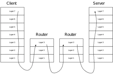
Figure 4 illustrates the typical path of a typical packet from the source to the destination. As we can see from the figure, the endpoints are seven-layer devices. On the server side, applications include HTTP web servers, TELNET terminal servers, FTP file servers, NFS file servers, and a SQL database server etc. Corresponding clients exist at the client side. Typically in such a client-server environment, the server centralizes the information, and the clients distribute the user interfaces. The CPU processing occurs both on the servers and on the clients.
2.1.3 Life on the Edge
well. This is particularly true for a segment of the Internet infrastructure, commonly referred to as the Internet Edge.
Where is the Internet Edge? If we see the Internet as a sphere with many servers and clients hanging from it, Internet edge is the crust of the sphere. If we zoom in, the Internet edge are all the devices that connect the private enterprise network with the public Internet
infrastructure. There emerged a large number of useful and powerful network software applications at the Internet edge, in the areas of security, traffic management, content distribution, and statistics collection. Let’s take a look at a few examples.
Firewall is possibly the most popular Internet edge software. It serves as a gatekeeper to a private network, allowing the legal traffic to pass, while stopping the illegal traffic. User sets up a policy to specify what traffic is legal, and all other traffic will then be dropped. This aims to prevent unauthorized access to the private network from the Internet. There are commonly two approaches for the implementation of a firewall. The first approach is to implement firewall as a packet filter. A packet filter firewall is a pseudo seven-layer device. It
incorporates a special layer-three module that peeks into the application-level information. It however does not terminate TCP or application connections. The second approach is to implement firewall as a proxy server. A proxy server is a seven-layer device that intercepts connections, pretends to be the server to the clients, and pretends to be the clients to the server. There are trade-offs between the two approaches. Packet filters are typically faster, whereas the proxy servers are regarded more secure.
releasing it onto the Internet. The VPN software on the receipt side decrypts it and sends it to the destination. This way, VPN software turns the very public Internet into a virtual private network between the offices.
Network Address Translation (NAT) is another interesting application at the edge. IP address is composed of 4 bytes of information. It means that it is possible to have about 4 billion unique IP addresses. While this may seem a lot, it is becoming not enough for the growing number of computing devices on the Internet. Fortunately, there are some special segments of IP address, such as 10.x.x.x and 192.168.x.x that are designated to be private IP addresses. NAT has become a common practice that within a private corporate network, the private IP addresses are used. When clients need to access the Internet, the edge devices will perform the “translation”. They will map the client IP address to a public IP address and a unique source port number. This allows multiple private clients to share one public IP address. This both solves the IP address scarcity problem, and also turns out to be an improvement of security and manageability as well.
Firewall, VPN, and NAT are just three examples of the myriad of network applications that emerged. As networking devices become more complex and sophisticated, avoiding single point of failures and performance bottlenecks in the networking infrastructure becomes a bigger challenge. This leads to the field of distributed systems.
2.2 What is a Distributed System?
system as a single computer.” One might ask, why do we need distributed systems? What advantage does it have over a single computer?
Distributed system is a technology in existence for more than 20 years. Its history is shorter than the history of the computer industry. In the early days of computers, distributed systems were not needed. There was Grosch’s law that the computing power of a CPU is proportional to the square of its price. This means that the performance to price ratio is higher for faster CPUs. To create a faster computing system, it is always cheaper to buy a computer with a faster CPU. This economics deemed distributed systems to be not necessary.
With the progress made in the microprocessor technology in the 70’s and 80’s, however, Grosch’s law no longer holds. The performance to price ratio has become a concave curve. This means that to perform the same number of computations per second, it is cheaper to use weaker CPUs, several of them, than to use a single but more powerful one. This new economics is one of the most important reasons for the birth of distributed systems.
In addition to the fact that distributed systems provide cheaper performance, it may also be able to achieve the performance level not at all achievable by a single CPU computer. Despite the strides made in the microprocessor technology, there are physical limitations to the speed of a processor. Being able to allow a number of CPUs to work together to perform the same task, simply add an independent dimension on how performance can grow. Combining it with the fastest chips can satisfy the computation needs not satisfiable otherwise.
system, without a distributed system, the company needs to replace the old computer with a more powerful new one. This operation may incur much trouble and cost. A distributed system can potentially allow the user to upgrade computation, communication, and storage capabilities of the system with complete transparency to all the clients.
This in effect achieves the virtualization of computers. A distributed system allows a user to see the computer as a logical device, rather than a physical device. Scaling up the physical device does not affect the logical identity of the computer, therefore, it will cause less trouble and cost. Another part of enabling the virtualization of computers is that not only addition of physical computers is transparent to the users, so is the removal of physical computers. With the addition of the nodes the system experiences performance scaling. With the removal of the nodes, the system incurs graceful performance degradation.
A distributed system can be designed to be fault-tolerant. In a fault-tolerant distributed system, when part of the system fails, the overall system continues to function. This is an important feature of a distributed system, sometimes even more important than all of the performance and scalability considerations combined for mission-critical applications. Not only is physical failure addressed by such a system, so can the routine maintenance work performed on the system without downtime. User can take offline part of the system to perform maintenance on, while the other part continues to take on the workload. The implementation of a fault-tolerant system can greatly increase the overall reliability and availability of an IT infrastructure.
2.2.1 Models of Distributed Systems
One of the first theoretical challenges is that a distributed system is not the most intuitive to model. Without a good model, correctness proof becomes very difficult. In the last twenty years a number of models emerged. These include the State Transition Systems [Lam and Shankar 1984], input-output automata [Lynch and Tuttle 1987; Lynch and Tuttle 1989], UNITY [Chandy and Misra 1988], and temporal logic of actions (TLA) [Lamport 1989; Lamport 1990]. These models explore the states of modules, and the events and actions that serve as the input and output of the state machine. They provide ways to formally prove the properties of a distributed system.
One of the first concepts in the distributed systems is the difference between a synchronous system and an asynchronous system. In a synchronous system, the relative speeds of processes are assumed to be bounded, and so are the communication delays between the computing nodes. In an asynchronous system, no such assumptions were made. It is much easier to prove properties of a synchronous system than of an asynchronous one. However, building a synchronous system is much more difficult, and in many cases impractical or impossible. Thus we’ll focus our attention on asynchronous systems in this dissertation.
Fault-tolerance in a distributed system is an important consideration. Not only because it is one of the key advantages of a distributed system, but also because a distributed system, by definition, employs multiple elements in a system. The larger the number of independent elements, the higher the probability that some of them will fail. This makes fault-tolerance an imperative requirement for larger distributed systems.
we classify the interesting failures in an asynchronous distributed system into the following five types.
Permanent Processor Failure: A processor fails by halting and it remains in the halting state. Also referred to as “crash” or “failstop”.
Transient Processor Failure: A processor fails by halting for a period of time.
Permanent Link Failure: A communication link between two processors fails by omitting all messages that are transmitted on that link.
Transient Link Failure: A communication link between two processors fails by omitting a subset of the messages that is transmitted by that link.
Byzantine Failure: A processor fails by exhibiting arbitrary behavior.
In an asynchronous system, each operation can be arbitrarily fast, or arbitrarily slow. This makes reliable failure detection an impossibility [Fischer et al. 1985]. The reason for the impossibility is that a failed processor can not be distinguished from a very slow one. This impossibility result is a fundamental result that shows the native challenge of creating a reliable distributed system in an asynchronous environment. Researchers have been searching for ways to go around this impossibility result. Possible workarounds include probabilistic approaches [Brancha and Toueg 1983] and specification weakenings [Neiger 1996; Franceschetti and Bruck 1999].
receivers at the same time. There are two categories of group communication: closed group communication and open group communication. In a closed group communication, the sender itself must be one of the nodes in the group. The purpose of a closed group
communication is to allow reliable and efficient communication within the cluster, so that the nodes in the cluster can successful perform one job. Open group communication allows the sender to be out of the group. This allows any computer in the world to communicate to the distributed system like communicating to a single entity.
2.2.2 Fault-tolerant Group Communication
Reliability in a group communication is more complicated than reliability in one-to-one communication, because there are more than one receiver. Reliability needs to be guaranteed even when any of the following three scenarios occur: A new node joins the group; an existing node voluntarily left the group; an existing node left the group due to its failure. This requires that all nodes currently in the group have agreement on the group membership. This problem is commonly referred to as the Group Membership Problem (GMP), and has been extensively studied in the field [Birman and Joseph 1987; Chandra et al. 1996].
Achieving agreement on group membership is a fundamental prerequisite for achieving reliable group communication. There are three aspects to reliable group communication:
Reliable delivery: If a receiver is able to receive messages, it must eventually receive all messages sent to it.
Consistent message ordering: When a group receives a series of messages, the nodes in the group must receive these messages in the same order.
The reliable delivery property for group communication is no different from the reliable delivery of a unicast message. A mechanism as simple as a receipt acknowledgement system provides a solution. The atomic delivery and consistent message ordering properties are unique to group communication. They make it easier to program a distributed system. Consistent ordering of multicast messages does not mean correct ordering of multicast messages. While message A may be sent before message B, as long as every node in the group agrees that message B happens before message A, consistent ordering of those two messages is achieved, and that ordering is BA. Logical clocks are often used to achieve the consistent ordering of multicast messages [Lamport 1978].
A number of group communication systems have been built. ISIS built at Cornell [Birman 1993; Birman and Van Renesse 1994; Birman and Joseph 1987] is a classic example. ISIS introduces the ideas of a loosely synchronous system and virtually synchronous system. As we mentioned previously, a synchronous distributed system is a beautiful thing, except that it is impossible to build. A loosely synchronous system weakens the requirements. In a loosely synchronous system, atomic broadcast messages arrive to all nodes in the group in the same order. A virtually synchronous system relaxes the requirement even further. It only
guarantees the correct ordering of messages that are causally related to each other.
et al. 1994], the TRANSIS project [Amir et al. 1992], the TOTEM project [Amir et al. 1995], and the MPI project [Gropp et al. 1999]. These projects assume a broadcast communication medium, and designed group communication systems of different scalability and overhead requirements.
2.2.3 Reliable Distributed Computing
On top of the reliable group communication substrate, reliable distributed computation can be designed. In a distributed system, the synchronization primitives that are easy to implement in a centralized system become much more complicated. In a centralized system, a critical region is used to control access to a shared resource, and guarantees the mutual exclusion that only one thread can access that resource at any one time. In a distributed system, a critical region becomes more difficult, but not impossible to implement. A lot of good research has taken place to study different ways to implement the critical regions and mutual exclusions [Raynal 1991; Chandy et al. 1983]. These methods differ in performance. Specifically, they differ in the amount of delay between the request for the mutex and the receipt of the mutex, and they differ in how many communication messages are needed in obtaining a mutex.
The most stringent consistency model is strict consistency. In this model, any read to a memory location x returns the value stored by the most recent write operation to x. To implement strict consistency in DSM, we must count the time of the read and write operations not at the moment when the requests are issued, but when the requests have been performed. Even under this assumption, a mutex needs to be acquired each time any memory location is to be accessed for write or read operation. This means that a significant delay is associated with every read or write operation. It is very costly, both in delays and in the amount of mutexes needed.
To improve performance, other weaker models have been proposed. These include sequential consistency [Lamport 1979], causal consistency [Hutto and Ahamad 1990], PRAM consistency [Lipton and Sandberg 1988], processor consistency [Goodman 1989], weak consistency [Dubois et al. 1986], release consistency [Gharachorloo et al. 1990], and entry consistency [Bershad et al. 1993].
Based on different consistency models, a number of DSM systems have been implemented. These include page-based DSM systems, such as IVY [Li 1986; Li and Hudak, 1989], shared-variable DSM systems, such as Munin [Bennett et al. 1990; Carter et al. 1991; Carter et al. 1994], and Midway [Bershad and Zekauskas 1991; Bershad et al. 1993], and object-based DSM systems, such as Linda [Gelernter 1985; Carriero and Gelernter 1986; Carriero and Gelernter 1989] and Orca [Bal 1991; Bal et al. 1990; Bal et al. 1992].
2.2.4 Distributed Applications
for scientific computation. Most of such systems were designed and constructed in the academia and research labs. Prominent examples include the NOW (Network Of
Workstations) project at Berkeley [Anderson et al. 1995], the SHRIMP project at Princeton [Damianakis et al. 1997], and the Beowulf project at NASA [Becker et al. 1995]. These systems can bundle together, tens, even hundreds of cheaper computers to create a powerful computing system that demonstrates superior performance to price ratio.
Meanwhile, in the computer industry, there also emerged a class of server clustering technologies that took advantage of the results in distributed systems. These systems are motivated by the need to scale up the performance of the servers in a client-server model. In the client-server world, one server usually needs to serve a large number of clients
simultaneously. This asymmetry leads to a major challenge: the scalability of the server. The microelectronics industry has been building ever-increasingly powerful CPU chips, so that they have enough capacity to power the server to handle a large number of less powerful clients. However, the economics of microelectronics tells us that there are two limitations to this approach. First, to increase the speed of a chip by 100%, the cost is usually much higher than 100%. Second, there is a physical upper bound on how fast a chip can be. These limitations lead to server solutions that use multiple computers. SunCluster and Microsoft Cluster Server are examples of such systems.
computing. The challenge this technology faces in getting adopted by the enterprise world is how to reduce the management cost once the servers reside on the thousands of desktops.
3 RAINCORE ARCHITECTURE AND PROTOCOLS
3.1 Architecture
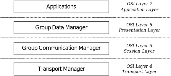
The advance of Internet is bringing together communication and computation. Raincore reflects this convergence by building distributed computing protocols into the communication stack. Raincore is first and foremost a distributed network computing architecture. The overall architecture of the Raincore Distributed Protocols and Services is described in Figure 5. As Figure 5 illustrates, the Raincore Distributed Services are mapped into Layer 4 through Layer 7 in the OSI seven-layer networking model.
Transport Manager Group Data Manager
Group Communication Manager Applications
OSI Layer 4 Transport Layer
OSI Layer 7 Application Layer
OSI Layer 6 Presentation Layer
[image:41.612.110.399.381.509.2]OSI Layer 5 Session Layer
Figure 5 Raincore distributed services architecture
cluster; Raincore will also help applications to mask failures so that it will not affect the availability of the overall network service.
The bottom-most layer in Raincore is the transport layer protocols and services. This layer provides reliable atomic message unicast services. Reliable delivery and flow control algorithms belong to this layer. We implemented a Raincore module called Transport Manager at this layer. Raincore Transport Manager can use redundant path to communicate to the destination, and will notify the upper layers if all delivery attempts for a message fail. It can transport a message of any size and is responsible of breaking it into smaller units in sending and reassembling the units in receiving. The atomicity of the transport is ensured that either the whole message arrives, or none of it arrives. We have also built in the sliding-window flow control mechanism that is useful when transporting a large packet of data.
The Raincore session layer protocols and services situate on top of the Raincore transport layer protocols and services, and provide group communication. The module we designed and implemented for this layer is called Group Communication Manager. It performs group membership management and reliable multicast with total ordering among the group members. In addition, it offers a mutual exclusion service that is useful for the presentation layer modules, as well as the applications.
Distributed applications can be developed on top of these three layers of services. Each layer provides an Application Programming Interface, making its features available to the
applications. In this chapter, we’ll go into more details into the protocols and algorithms at the transport layer and the session layer. In the next chapter, we’ll introduce some application examples that use the Raincore services.
3.2 Transport Manager
The Raincore Transport Manager is a module placed in the transport layer within the Raincore architecture. It is a module situated at the bottom of the Raincore stack and requires the availability of an unreliable unicast interface to send and receive packets. In typical implementations, it uses either an UDP socket or raw socket as the packet sending and receiving interface. However, it is not limited to that and can use any packet-sending interface. This service can be used to communicate between nodes over a Local Area Network or a Wide Area Network. And there is no limitation to the Layer-2 protocols.
Raincore Transport Manager provides an atomic reliable unicast transport and failure-on-delivery notification to the upper layer. One might ask, why don’t we use the industry-standard TCP. Both TCP and TM provide reliable unicast and flow control. However, Raincore Transport Manager provides the following functionalities that are not available in TCP:
1. Raincore Transport Manager is an atomic connectionless message delivery mechanism. A packet is either completely delivered, or not delivered at all. It does not employ the concepts of connections or streams. Therefore, there is no connection state
2. The Transport Manager generates notification to the upper layer both when it receives the acknowledgement from the destination, as well as when all sending efforts have failed. The second notification, the failure-on-delivery notification, is particularly significant, as it serves as a local-view failure detector for the Raincore Group Communication Manager.
3. The Transport Manager allows one node to communicate to another node using multiple physical addresses. It also allows a node to automatically resend a packet if earlier attempts failed. It will exhaust all of the configured resends on all physical addresses, before sending the failure notification to the upper layer. This allows redundant links between the nodes in the group, therefore making the group more resilient to link failures and less likely being partitioned. Packet-sending strategy using multiple physical addresses can be specified, where the physical addresses can be targeted in sequential or parallel order.
When the upper layer calls the Raincore Transport Manager to send a message to another node, the TM is responsible for partitioning the message into packets. The size of the packet depends on the packet-sending interface and the Layer-2 protocol that the TM is using. For sending UDP packet over Ethernet, it is a good idea to keep the packet size under 1.5 KB to avoid UDP packet fragmentation. TM employs a sliding-window protocol to provide reliable delivery and flow control. The receiving side won’t pass the message to the upper layer until all packets related to that message have been received.
3.3 Group Communication Manager
Group communication is a key component for a distributed system in a network environment, similar to its importance in other distributed environments. Its goal is to provide a reliable and efficient many-to-many communication transport, and to continue to function as nodes leave and join the group, or the cluster. We characterize this functionality to be a session layer functionality and create a Group Communication Manager module to carry it out.
Group Communication Manager maintains the consistent group membership of the cluster and serves as reliable multicast transport to share state information among the member nodes. This module is used as a group communication transport to share arbitrary application state among the cluster group and to facilitate transparent fail-over of traffic from a failed node to a healthy node, without the clients or the servers being aware of the failures.
Group Communication sits on top of the Transport Manager. Multiple Group
Communication Managers can coexist on the same node and use different channels of the same Transport Manager.
3.4 Group Membership Specifications
In an asynchronous distributed system, a Group Membership Protocol provides nodes in the cluster with a consistent view of the membership of that cluster. When a change in the membership occurs, either by nodes failing or leaving the cluster, or by new nodes joining the group, all current members of the cluster need to achieve agreement on the current
It has been shown that it is impossible to find solution to the consensus problem in
asynchronous environment [Fischer et al. 1985] and this result has been extended to group membership agreement [Chandra et al. 1996]. The root of the impossibility lies in the lack of a reliable failure detector: one cannot distinguish between a failed node and a slow node. However, as we mentioned, different distributed systems have been built despite of this impossibility. This motivated a series of recent research that explored nontrivial ways to weaken the specification of the Group Membership problem [Neiger 1996; Franceschetti and Bruck 1999].
It is a challenge to define a specification that is achievable, and yet no trivial protocol can achieve it. Franceschetti and Bruck proposed a specification based on the idea of Quiescent State. They accepted that when local failure monitor continues to send input, it is difficult for the protocol to make progress. But once local failure detector stops sending input, each process will enter Quiescent State, and progress can be made during the Quiescent State. In this section, we will use the their specification and prove that the Raincore Group
Communication Manager protocols meet that specification.
Each process p maintains two fundamental data structures: a set vp that contains the current local view of the membership, and a sequence Sp = [Vp1, Vp2, …, Vpk, …] of global views. A process’s local view, vp, contains a set of processes. These processes are currently live from this process’ perspective. The process modifies the local view, vp, based on the inputs from the local failure detector. The global view vector Sp contains an ordered and indexed list of global views. Each global view contains a set of processes. A Group Membership Protocol specifies when and how to extend the global view sequence Sp with new global views, based on changes in the local view vp, and doing so consistently at different processes.
To formally present their group membership specification, we need to first define Consistent History and Quiescent State.
Definition 3.1 Consistent History. A set of processes Q has a consistent history of views if the sequences S are the same at all processes in the set, unless sets Vpj and Vqj are disjoint. Namely:
∀p, q ∈ Q ∀ j: (Vpj = Vqj) ∨ (Vpj ∩ Vqj = ∅),
where p and q are processes IDs and Vpj and Vqj are the j-th elements in p’s and q’s global sequence of views respectively.
Definition 3.2 Quiescent State. A process p is in a quiescent state if it does not change its sequence of global views anymore. Namely:
(Sp = [Sp]),
They then define a specification consisting of four properties. If an algorithm meets all four of these properties, it has solved the Group Membership Problem with this specification.
Property 1 Agreement. At any point in time all processes have a consistent history.
True ⇒ (Consistent History)
Property 2 Termination. If there are no more changes in their local views, all processes eventually reach a quiescent state.
∀p: (vp = [vp]) ⇒ ◊(Quiescent State),
where each [vp] is a constant set.
Property 3 Validity. If all processes in a view v* perceive view v* as their local view and have reached a quiescent state, they must have view v* as the last element of their sequence of global views.
∀p ∈ v*: [Quiescent State ∧ (v p = v
*)] ⇒ ∀p ∈ v* (V
pmax = v *),
where Vpmax is the last nonempty set in the sequence Sp.
Property 4 Safety. Once a view is committed in the sequence of global views, it cannot be changed.
(Vpj = v*) ⇒ (Vpj =v*)
guarantees that all processes in the system enter quiescent state once there is no more input from local failure detectors. The third property expresses progress that if all processes have agreement on their local views at quiescent state, they will commit it to the global view. The fourth property rules out some trivial solutions by preventing processes changing old views in their global view sequence.
In the next subsection, we’ll present the group membership protocol used in GCM. We’ll also prove that this protocol meets the above specification.
3.5 Group Membership Protocol
At the heart of the Raincore Group Communication Manager is a token-ring protocol. This protocol is the basic component in providing the consistent group membership, reliable multicast and mutual exclusion services. Token ring is one of the best-known protocols used in the distributed computing world. Started with the work by Chang and Maxemchuk [Chang and Maxemchuk 1984], and continued both in the ISIS/HORUS projects [Birman and van Renesse 1994; van Renesse et al. 1994] and the TOTEM project [Amir et al. 1995], token ring have been used to sequence the broadcast message ordering and manage the group
membership.
Group Communication Manager will take that notification as an input and take appropriate action depending on the internal state.
[image:50.612.106.437.147.188.2]Token Signature Global View Number Pointer to dest. node Pointer to current node Nodelist Sequence Number
Figure 6 Token message format
The fields on a token are shown in Figure 6. The signature field indicates that this is a token message. After the signature field is the sequence number field. Every time a token is being passed from one node to another, the sequence number on the token is increased by one. Also contained in the token is a field called nodelist. It is a cyclic ordered list of all nodees that the token traversed in the last pass around the ring. There is a pointer that points to the current in the nodelist, and a pointer that points to the destination node in the nodelist. Last but not least, the token contains the global view number that indicates the largest index in the committed global view sequence S = [V1, V2, …, Vk].
911 Signature Pointer to Orig. node Pointer to dest. node Pointer to current node Nodelist Sequence Number Status
Figure 7 The 911 message format
[image:50.612.109.487.457.495.2]received token on the originating node. At the end is a status field, which can hold one of three values: YES, NO, or REJECT.
globalView lastToken localView newNodes
Seq. lastToken
[image:51.612.109.436.148.187.2]globalView Number
Figure 8 Local data structures on each node
Each node keeps a number of local data structures as well (Figure 8). First of all, each node keeps a vector of consistent history of group memberships, called globalView. The most recent group membership is referred to as lastGlobalView, and its index number in the globalView vector is called globalViewNumber. In addition, each local node keeps a copy of the last received token, stores it in lastToken. The sequence number of the lastToken is lastTokenSeq, and the nodelist on lastToken is localView. This shows that the nodelist on the token is in effect the localView of the node that it last resides. Furthermore, each node keeps a queue of newNodes, which lists all the nodes that are applying to join the cluster and not in the cluster yet.
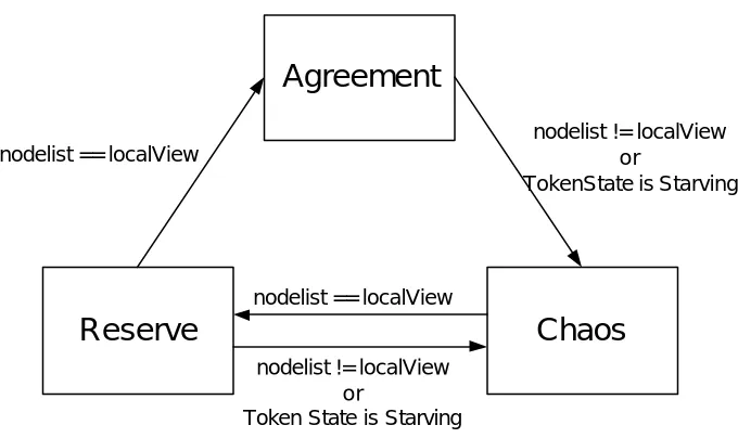
Agreement
Chaos
Reserve
nodelist != localView or
TokenState is Starving
nodelist == localView nodelist == localView
nodelist != localView or
[image:52.612.128.468.80.282.2]Token State is Starving
Figure 9 View State transition diagram
There are three View States (Agreement, Chaos, and Reserve). When a node is in Agree state, it indicates that this node’s local view is in agreement with the local view of the other nodes in the cluster. A node enters Chaos state from Agreement state when it notices difference between its localView and the nodelist on the token. This indicates that there is an
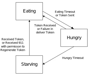
Eating
Starving
Hungry
Eating Timeoutor Token Sent
Token Received or Failure in deliver Token
Hungry Timeout Received Token,
[image:53.612.112.410.78.334.2]or Received 911 with permisson to Regenerate Token
Figure 10 Token State transition diagram
There are three Token States (Eating, Hungry, and Starving). A node enters the Eating state when it receives a valid token. A token is valid when its sequence number is bigger than the lastToken Sequence number. When a node is in the eating state, it will keep the token for a preconfigured eating time, before trying to send the token to the next node. The transition from Eating state to Hungry state is triggered by the eating timeout. The node will update the token and pass the token to the Transport Manager to send it out. It enters the Hungry state after the token is passed to the Transport Manager. The normal view state transition can only occur in Eating token state.
Starving token state, it would enter Chaos View State. The node put the sequence number of its lastToken on the 911 message and initiated the status field with a YES, assuming that it will have the right to regenerate the token. If the token has not been lost, or if there is another node that has received a token with a higher sequence number, or the same sequence number and a higher node ID, it will veto the 911 message by filling the status field with a NO.
This 911 mechanism ensures that one and only one node in the cluster will regenerate the token. In the case when the token is lost, every live node sends out a 911 request after its hungry timeout expires. Only the node with the latest copy of token (i.e., the token with the highest sequence number) will be granted the right to regenerate the token. That node would receive its own 911 message with the status field YES. It will enter Eating state and create a new token making a copy of its lastToken.
The 911 message is not only used as a token regeneration request, but also as a request to join the membership. When a new node wishes to participate in the membership, it sends a 911 message to a ny node in the group. The receiving node notices that the originating node of this 911 is not a member of the group, and therefore treats it as a join request. The next time before the receiving node sends out the token, if the new node has not yet been added to the nodelist on the token, it will add it to the nodelist on the token, and will enter Chaos View State. It then sends the token to the new node. The new node thereafter enters Chaos View State as well. When all nodes commit the nodelist to their globalView vector, the new node becomes part of the group.
as well as the nodelist on the token, and enter Chaos view state. It will then pass the modified token to the Transport Manager to resend it and enter Hungry token state.
The Transport Manager also sends failure-on-delivery notification when it fails to send a 911 message. In this case, the GCM will only modify the destination node on the 911 message and send it via TM again. There is also a timeout associated with the Starving token state. When a node remains in the starving state for a while without receiving the token or permission to regenerate the token, it will send out a 911 message again. Figure 10 shows the state transition diagram for the Token States triggered by events.
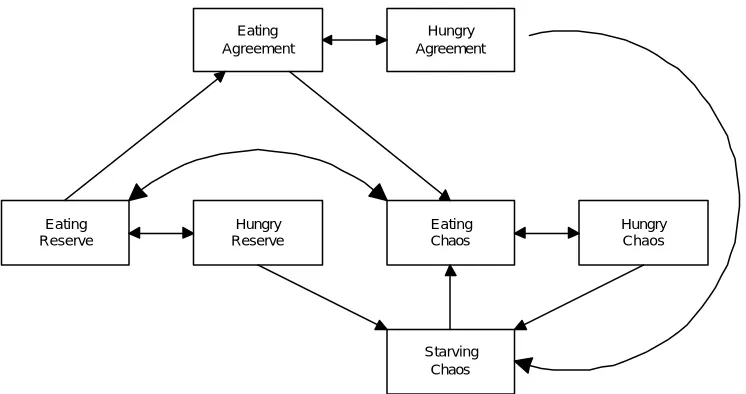
Eating Agreement Hungry Agreement Starving Chaos Hungry Chaos Eating Chaos Hungry Reserve Eating Reserve
Figure 11 Overall state transition diagram
1. Initialization
ViewState=CHAOS; tokenState=EATING; Initialize local data structures;
Initialize the token with a unique intial sequence number; Send Token;
TokenState=HUNGRY; Start HUNGRY timeout;
2. Token Received.
If (tokenState == EATING) {
Drop the token; }
else if (sequence number mis-match) {
Drop the token; }
else if (tokenState == HUNGRY or tokenState == STARVING) {
tokenState=EATING;
Start the clock for EATING timeout; Update token.currentNode; If (viewState == AGREEMENT) {