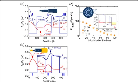
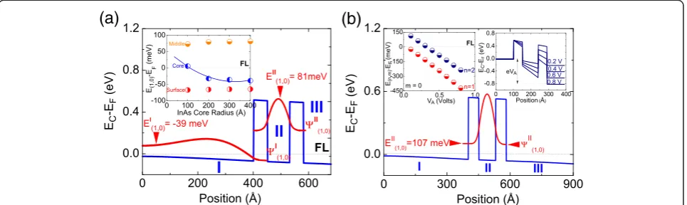
Electronic properties of core shell nanowire resonant tunneling diodes
Full text
Figure

Related documents
However, if retailers can convince shoppers to impulse purchase in the same way as they do in store, they have the opportunity to increase sales significantly.. Encouraging
The generated test stimulus can be used to find out the static (offset error, gain error, integral nonlinearity error and differential nonlinearity error) and
So there is need to develop a mechanism which can adopt the dynamic topology and can also control the MAC contentions and interference while maintaining the different Quality
We discarded the results of some earlier experiments, notably when we measured NV-RAM space as a function of optical drive speed on a Nintendo Gameboy.. Gaussian
In this paper we have presented the literature review in the field of reduced time complexity by using data mining and fuzzy logic techniques and found that still we
CVVH, continuous veno-venous hemofiltration; CVVHD, continuous veno-venous hemodialysis; CVVHDF, continuous veno-venous hemodiafiltration; K CALC , calculator-estimated
In summarizing the results, we can conclude that, for the charged Higgs searches, the most suitable channel from cross section point of view is charged Higgs pair produc- tion
Th ere is some evidence from observational studies and small, randomised, prospective trials that statin treat- ment post-injury, or prior statin treatment, may have a benefi cial
