ISSN(Online): 2319-8753 ISSN (Print): 2347-6710
I
nternational
J
ournal of
I
nnovative
R
esearch in
S
cience,
E
ngineering and
T
echnology
(An ISO 3297: 2007 Certified Organization)
Website: www.ijirset.com
Vol. 6, Issue 4, April 2017
Comparative Analysis of Different Lateral
Load Resisting System for RCC Structure
Shubham P. Dhoke1, Bhavini V. Ukey 2, Amol V. Gorle 3
B.E. Student, Department of Civil Engineering,J.C.O.E.T., Yavatmal, Maharashtra, India1
B.E. Student, Department of Civil Engineering, J.C.O.E.T., Yavatmal, Maharashtra, India2
Assistant Professor, Department of Civil Engineering, J.C.O.E.T., Yavatmal, Maharashtra, India3
ABSTRACT: Due to development in construction technology and structural systems growth of high rise building increases. Now-a-days in modern tall buildings, lateral loads induced by earthquake orwind are often resisted by a various lateral load resisting system (viz., Beam Column System, Frame Tube System, Shear Wall & Frame System and Diagrid System, etc.). This paper contains comparative analysis of various lateral load resisting system (i.e., Beam Column System, Frame Tube System and Diagrid System). Modelling and analysis of different lateral load resisting
system done in ETABS-2015 software. This paper gives information about various lateral load resisting system and
which of them is more beneficial.Lateral load plays an important role while designing any multi-storey building, so study & analyse the lateral load resisting system. The comparison oflateral load resisting systems is done by using
Response Spectrum Method on the basis of various parameters such as storey displacement, storey drift, storey forces
and modal time period.
KEYWORDS: Storey displacement, Stiffness, Bracing, Frame Tube, Diagrid, Shear Wall, Dynamic, Response Spectrum Analysis, ETABS.
I. INTRODUCTION
Now a day, India moving towards the developing country through an economy, huminite for that infrastructure places plays an important role. Bhuj Earthquake, Killari Earthquake, Chamoli Earthquake, Jabalpur Earthquake and Uttarkashi Earthquake etc. this type of earthquake cause casualties and damages in higher quantity. This type of moment move India to lack behind from become developed country. In the earthquake occurrence area, random rubble stone masonry structure, cement concrete block construction, earthen building has been observed mostly. It is important to construct the structure resistant to earthquake.So, we start to construct these types of building.For constructing such a structure resistant to earthquake requires higher construction cost. But, according to the architecture point of view we must check the building for all the type of loading (viz., seismic load, lateral loads, wind load, etc.).So, that the building is withstand in proper manner & the life span of building becomes more than other and providing safety to peoples.
Seismic zone plays an important role in design of earthquake resistant structures, because the zone factor changes as the intensity of earthquake changes from low to very severe. For the occurrence of earthquake mainly two types of lateral forces act on structure i.e. wind force and seismic force. For protecting structure from these forces and damages, lateral load resisting system is design in earthquake prone areas. Some of lateral load resisting structures are Diagrid System, Frame Tube System and Beam Column System, etc.
OBJECTIVE
To determine Story displacement
,
Modal time period, Story forces in both vertical and horizontal direction. To determine the economical and convenient lateral load resisting system.
ISSN(Online): 2319-8753 ISSN (Print): 2347-6710
I
nternational
J
ournal of
I
nnovative
R
esearch in
S
cience,
E
ngineering and
T
echnology
(An ISO 3297: 2007 Certified Organization)
Website: www.ijirset.com
Vol. 6, Issue 4, April 2017
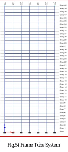
Fig.1) Beam Column System Fig.2) Frame Tube System Fig.3) Diagrid System
II. LITERATURE SURVEY
These are some literature reviews while preparing this paper.
Rasool Owais and Tantray Manzoor Ahmad “Comparative analysis between different commonly used lateral load resisting systems in reinforced concrete buildings.” In this paper, they studied different cases of lateral load resisting systems. They check efficiency by comparing nodal displacements, relative displacement, maximum moments and shear forces. They use square grid of 12m in each direction in seismic zone 5. They made analysis on the basis Staad-proV8i software. They found nodal displacement both transitional and rotational for shear wall is least, bending moment and displacement is comparatively less in bracing system than other systems.
Abhijeet Baikerikar, Kanchan Kanagali, “Study of lateral load resisting systems of variableheights in all soil types of high seismic zone.” In this paper, they studied shear wall, bracing, moment resistance frame & lateral loads act on higher rise building. They describe how to overcome from earthquake loading and which system is best among other. They mentioned performance of bracing system is better than other system in earthquake prone area.
III.SYSTEM DEVELOPMENT
In this paper, comparison of different lateral load systems is done. Following lateral load resisting systems are considered 1] Beam Column System 2] Frame Tube System and 3] Diagrid System and these systems are discussed in short.
1] Beam Column System: -In Beam Column system, the structural members are made of beam and column. Beam is the horizontal member of structure & it transfers the load to column.Column is a vertical structural member composed to transmit a compressive load to hard stratum foundation of the structure.
2] Frame Tube System: -In Frame Tube System, the combination shear wall and of beam column is provided while designing the structure. Sometimes the shear wall is provided internally in core of the structure, it makes the tube of high strength it forms the frame tube system.
3] Diagrid System: -Diagrid System is nothing but the grids of RCC or Steel provided in structure diagonally with the specific geometry.
This is general information about the various lateral load resisting system. Now moving to the main work of this paper, for achieving economy in construction material and material constant in all lateral load resisting system. Calculating material in such a way that the quantity of material in every system is same. The details of material and dimensions of structural members are given Table-1.
In this paper three models are constructed in ETABS software and they are i) Beam Column System, ii) Frame Tube System and iii) Diagrid System with varying orientation of column. Foranalysis of different lateral load resisting systemadopt Response Spectrum Method. The plan and elevation of various system is given in following figures.
ISSN(Online): 2319-8753 ISSN (Print): 2347-6710
I
nternational
J
ournal of
I
nnovative
R
esearch in
S
cience,
E
ngineering and
T
echnology
(An ISO 3297: 2007 Certified Organization)
Website: www.ijirset.com
Vol. 6, Issue 4, April 2017
The following figures shows the Elevation of various lateral load resisting system.
Table 1: - Details of Materials for Modelling
IV.PERFORMANCE AND ANALYSISWITH EXPERIMENTAL RESULTS,TABLES AND GRAPHS
Data Required for Modelling Number of
Storey Data Beam Column System Frame Tube System Diagrid System
40
Beam Size bXd (in mm) 300X450 300X450 350X490.9
Column Size bXd (in mm) 300X550 230X248.89 609.3X609.3
Bracing bXd (in mm) No No 350X555.6
Slab Thickness (in mm) 130 146 130
Shear Wall Thickness (in mm) No 110 No
Concrete Grade M30 M30 M30
Grade of Steel (in N/mm²) 415 415 415
Live Load (in kN/m²) 3 3 3
Floor Finish (in kN/m²) 1.5 1.5 1.5
Roof Live Load (in kN/m²) 1.5 1.5 1.5
Zone (City-Nagpur) II II II
Zone Factor (Z) 0.1 0.1 0.1
Response Reduction Factor (R) 5 5 5
Importance Factor (I) 1 1 1
Each Storey Height (in m) 3 3 3
Plan (in meter) 36X36 36X36 36X36
ISSN(Online): 2319-8753 ISSN (Print): 2347-6710
I
nternational
J
ournal of
I
nnovative
R
esearch in
S
cience,
E
ngineering and
T
echnology
(An ISO 3297: 2007 Certified Organization)
Website: www.ijirset.com
Vol. 6, Issue 4, April 2017
0 1 2 3 4 5 6 7 8 9
1 2 3 4 5 6 7 8 9 10 11 12
T
im
e
(s
ec
o
n
ds
)
Mode
Comparative Graph of Time Period
Beam Column System Frame Tube System Diagrid System
0 500 1000 1500 2000 2500 3000 3500
0 5 10 15 20 25 30 35 40 45
F
o
rc
es
(kN
)
No. of Storey
ComparativeGraph of Storey Forces
Beam Column System Frame Tube System Diagrid System
Computer & structures Inc. (CSI) ETABS 2015 software is used for dynamic analysis and determine the response of structures. The comparative analysis of different lateral load resisting system of G+39 storey of RCC structure has been done in ETABS-2015 software. The comparison of performance G+39 storey of different lateral load resisting system is carried out. Comparison based on parameters like story displacement, storey forces and modal time period& storey stiffness.
Following figure shows the comparative result of different lateral load resisting system.
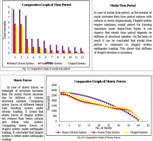
Fig. 7) Comparative Graph of modal time period
Modal Time Period
In case of modal time period, as the number of mode increases then time period reduces with reduces in storey displacement. Diagrid system require minimum modal period for forming maximum mode shape.From figure, it can observe that modal time period depends on stiffness of structural member. On the basis of result it can be concluded that modal time period is minimum in diagrid system earthquake loading. This shows that stiffness of diagrid structure is increases.
Storey Forces
In case of storey forces, as theheight of structure increases then the storey forces decrease due to stiffness of various structural member. Comparing storey forces of different lateral load resisting system under seismic loading. It found that storey forces of diagrid system are reduces than beam column
and frame tube system.
Comparing storey forces of diagrid system under earthquake loading. It concluded that diagrid system is better under earthquake
ISSN(Online): 2319-8753 ISSN (Print): 2347-6710
I
nternational
J
ournal of
I
nnovative
R
esearch in
S
cience,
E
ngineering and
T
echnology
(An ISO 3297: 2007 Certified Organization)
Website: www.ijirset.com
Vol. 6, Issue 4, April 2017
0 1000000 2000000 3000000 4000000 5000000 6000000 7000000 8000000 9000000 10000000
0 10 20 30 40 50
S ti ff n es s (kN /m )
No. of Storey
Comparative Graph of Storey Stiffness
Beam Column System Frame Tube System Diagrid System 0 0.05 0.1 0.15 0.2 0.25
0 10 20 30 40 50
D is pl a ce m en t (m )
No. of Storey
Comparative Graph of Storey Displacement
Beam Column System Frame Tube System Diagrid System
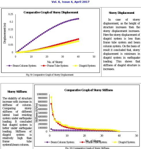
Storey Stiffness
The stability of structure increase with increase in
stiffness of column.
Comparing storey
stiffness of different
lateral load resisting
system under earthquake loading. It concluded that diagrid system is better under earthquake
loading. Stiffness of
diagrid system is
relatively high than
frame tube
system&beam column.
Fig. 10) Comparative Graph of Storey Stiffness
V. CONCLUSION
The stability of structure increase with increase in stiffness of column. As the stiffness of column increase, it reduces the displacement of structure.
On the basis of result, it may conclude that diagrid system is more beneficial than other lateral load resisting system. Fig. 9) Comparative Graph of Storey Displacement
Storey Displacement
In case of storey
displacement, as the height of structure increases then the storey displacement increases. Here the storey displacement of diagrid system is less than frame tube system and beam column system. On the basis of result it concluded that, storey displacement is minimum in diagrid system in earthquake
loading. This shows that
ISSN(Online): 2319-8753 ISSN (Print): 2347-6710
I
nternational
J
ournal of
I
nnovative
R
esearch in
S
cience,
E
ngineering and
T
echnology
(An ISO 3297: 2007 Certified Organization)
Website: www.ijirset.com
Vol. 6, Issue 4, April 2017
On the basis of result, it can be concluded that stiffness of diagrid system is increase than beam column and frame tube system. Due to stiffness increases, storey displacement and modal time period are reduces, that means damping of structure is increases. Hence, stresses induced due to displacement is reduces.
On the basis of above results, it is found that structure with diagrid system gives better performance than others with same material consumption of lateral load resisting system. Diagrid system has good aesthetic appearance as well as effective in performancethan Frame Tube System and Beam Column System. On the basis of results provided by ETABS-2015 it may conclude that the diagrid system gives good results than others as in case of time period, displacement, storey forces and storey stiffness.
REFERENCES
[1] IS-1893 (Part 1): 2002, “Criteria for earthquake resistant design of structures, part 1-general provisions and buildings”, fifth revision, Bureau of Indian Standards, New Delhi, India.
[2] Khushbu Jani, Paresh V. Patel, “Analysis and design of diagrid structural system for high rise steel buildings”,ELSEVIER, page no. 92- 100, 2013.
[3] Rasool Owais, Tantray Manzoor Ahmad, “Comparative analysis between different commonly use lateral load resisting system in reinforcement concrete building”,Global Journal of Researches in Engineering: E, Civil and Structural Engineering, Volume 16, Issue 1, Version 1.0,page no. 47-53,2016.
[4] Abhijeet Baikerikar, Kanchan Kanagali, “Study of lateral load resisting system of variable heights in all soil types of high seismic zone”,International journal of Engineering Research & technology,Volume 03, Issue10, page no. 109-119,Oct-2014.
[5] Ajinkya P. Gadkari,N. G. Gore, “Review on behavior of outrigger structural system in high rise building”, International journal of Engineering Development of Research,Volume 4, Issue 2, page no. 2065-2073, 2016.
[6] Venkata S. Kumar, Surendra Babu, Usha Kranti, “Shear wall-A review”, International journal of innovative research in science, Engineering and Technology (IJIRSET), Volume 3, Issue 2, page no. 9691-9694, February-2014.
[7] M. D. Kevadkar, P. B. Kodag, “Lateral load analysis of RCC building”, International journal of Modern Engineering Research (IJMER),Volume 3,Issue3,page no.1428-1434, May-June-2013.
[8] Tanha B.Shah, “Literature Survey on Analysis of Multi-Storey building considering hybrid structure”, International journal of innovative research and development, Volume 1, Issue 2, page no. 1-9.
[9] Tejaswini R. M.,Rashmi A. R., “Analysis and comparison of different lateral load resisting structural forms”, International journal of engineering research and technology (IJERT), Volume 4, Issue 07, page no. 827-833, July-2015.
[10] Kiran Parmar, Mazhar Dhankot, “Comparative study between dual system for lateral load resistance in buildings of variable heights”, International Engineering Research journal of & Technology (JIKRCE),Volume 02, Issue 02, page no. 303-306,Nov-12 to Oct-13.
[11] Akshay A. Khanorkar, S. V. Denge, Dr. S. P. Raut,“Belt truss as lateral load resisting structural system for tall building.”, International Journal of Science Technology & Engineering (IJSTE), Volume 2, Issue 10, page no. 658-662, April-2016.
[12] Piyush Gupta, Dr. Neerja, “Analysis of various RCC lateral force resisting system and their comparison using –ETABS”, International journal of latest trends in engineering and technology, Volume 6, Issue 4,page no. 175-182, March-2016.
[13] Prathith Hedge, Dr.Aakshatha Shetty, “Seismic analysis of RC frames using lateral load resisting system”, International journal of technical research and applications,Volume 04, Issue 03,page no. 197-200, May-June-2016.
[14] Kiran Kamath, Sachin Hirannaiah, Jose Camilo Karl, Barbosa Noronha, “Diagrid structure square in plan-pushover”, International journal of innovative research in science, engineering and technology (IJIRSET), Volume 05, Issue 09,page no. 48-52, May-2016.
[15] Dr. H. M. Somasekharaiah, Mr. Madhu Sudhana, Y. B., Mr. Md. Muddasar Basha S., “A Comparative Study on Lateral Force Resisting System for Seismic Loads”,International Research Journal of Engineering and Technology (IRJET), Volume 03, Issue 08, page no.1138-1144, August-2016.