Design Analysis and Optimization of
Go-Kart using Finite Element Analysis
Jawagar Shrehari J1, Raagul Srinivasan K A2
B.E. Student, Department of Mechanical Engineering, Dr. N.G.P. Institute of Technology, Coimbatore, India1,2
ABSTRACT: The objective of this paper is to highlight the design report of theGo – Kart vehicle. The performance of a Go-kart depends a lot on the chassis design. Thus, this project takes a look at the investigation of chassis design, simulation and fabrication. We approached our design with a rough 2D sketch of the chassis and we created the virtual assembly of our go-kart using a CAD modeling software Solid works and the analysis was done using Ansys16 software. Based on the analysis the model was retested with boundary conditions under the practical parameters. So the design focuses on safety, serviceability, strength, ruggedness, standardization, cost, ergonomics and aesthetics
KEYWORDS: Go-kart, Chassis, Finite element analysis (FEA), Drive Train
I. INTRODUCTION
The design objectives set out to be achieved were three simple goals applied to every component of the car: durable, light-weight, and high performance, to optimizing the design by avoiding over designing.In order to ensure that the design of the chassis achieve the standard level, detailed analysis was made through ANSYS16 software. The purpose of this simulation was to investigate the strength and the flexibility of the chassis. The simulations carried out with several altered parameters for various impact tests, which would also help in reducing the cost. With this we had a view of our kart. Our primary objective is to design a safe and functional vehicle based on rigid and torsion free frame, well mounted power train and with a bit of innovation are the key aspects in our design.
II. RELATED WORK
Description Specification Description Specification
Wheel Base 1260 mm Engine &Transmission 8.4 Bhp @7500 rpm
OverallHeight 620 mm Max.Torque 8.3 Nm @5500 rpm
Overall Length 1900 mm Gear ratio(rear axle) 1:1:5
Overall width 1270 mm Steering Ackerman(pivot type)
Ground
clearance 2.5” inches
Turning
Radius 2.5M
Overallweight 160 Kg Brake Disc Type
Material Seamless mild steel
(asper analysis) Tire size
11/7.10-5(rear) 10/4.50-5(front)
III. OPTIMIZATION OF CHASSIS
A. MATERIAL SELECTION
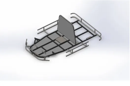
Fig 1. 3D View of Chassis
strength material is important in a roll cage because the roll cage needs to absorb as much energy as possible to prevent the roll cage material from fracturing at the time of high impact. Mild Steelhas chosen for the chassis because it has structural properties that provide a low weight to strength ratio.The Frame was designed using 1.25 inch diameter tube with a thicker wall of 3 mm is used instead of 1.5 inch diameter tube with a thinner wall for manufacturability purposes. Although the thinner wall, 1.25 inch diameter tube would be slightly lighter than the thicker wall, 1 inch diameter tube, it would have been more material and more difficult to weld. Then it is also assured by analysis in solid works software. The various Physical properties and chemical properties of the material are listed in Table II and Table III are as follows.
Table II: Material Properties
S.No. Properties Values
01. Tensile strength, Ultimate 450 Mpa
02. Tensile strength, Yield 380 Mpa
03. Bulk modulus 200 Gpa
04. Shear modulus 80 Gpa
05. Modulus of elasticity 200 Gpa
06. Poisson’s ratio 0.29
07. Elongation at break 16%
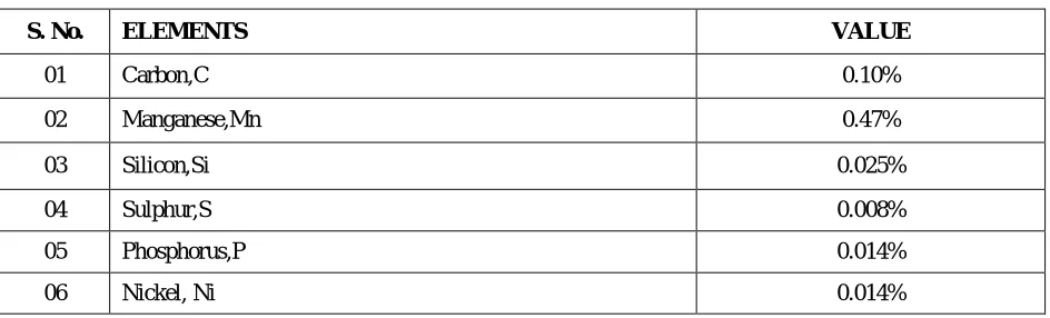
Table III: Chemical Composition
S. No. ELEMENTS VALUE
01 Carbon,C 0.10%
02 Manganese,Mn 0.47%
03 Silicon,Si 0.025%
04 Sulphur,S 0.008%
05 Phosphorus,P 0.014%
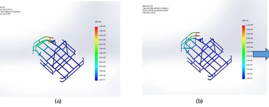
B. DEFORMATION TEST OF THE CHASSIS
(a) (b)
Fig 2:(a) Failed Chassis (b) Rectified Chassis
C. FRONTAL IMPACT ANALYSIS
Generally in the case of pure elastic collision in frontal impact the linear velocity remains at 60Kmph according to ENCAP (The European new car assessment program).Hence the value of force is calculated by mass moment equation that is-F = P×∆T
Where ∆T is the duration of time, generally the collision takes place for a very short duration of time. We assumed this time as ∆T = 1.01 seconds. And the gross weight of the vehicle is Estimated some around (M=180 KG), hencethemoment of the vehicle at 60 Km/h or 16.667 m/s that is-
P = m × v P = 180 × 16.667 P =3000kgm/s
And the frontal impact force i.e.- F = P × ∆T
Where, P = m × v P = 180 × 20 P = 3600 kgm/s
And the rear impact force- F = P× ∆T
F = 3000 × 1.10 F = 3960 N
Now the calculated force were placed on the frontal part of frame by keeping the rear part fix on Ansys16and the result along with the image as
A side impact analysis is very necessary and the boundary conditions are taken relating to the real life situation that a go kart will experience. In the case of collision by side impact the value of the impact force generated is calculated in the same way as in front impact. For the side impact the velocity of vehicle is taken 72kmph or 20m/s according to ENCAP Standard and then the force Is calculated i.e.- F = P × ΔT
Where, P = m × v P = 180 × 20 P = 3600 kgm/s
The side impact force – F = 3600 × 1.10 F = 3960 N.
Hence the calculated force were placed on one side of the modal of frame while keeping another side fixed and the stresses were simulated the image is shown as-
E. REAR IMPACT ANALYSIS
The rear impact force is also calculated in the same way as remaining two. In this case the velocity of collision was taken 72kmph or 20 m/s by the calculations and also as according to the ENCAP standards.
The calculations are as- Where, P = m × v P = 180 × 20 P = 3600 kgm/s
And the rear impact force- F = P× ∆T
F = 3000 × 1.10 F = 3960 N
Hence the calculated value of the rear impact force was placed on the rear part of the frame while keeping the frontal part fixed.
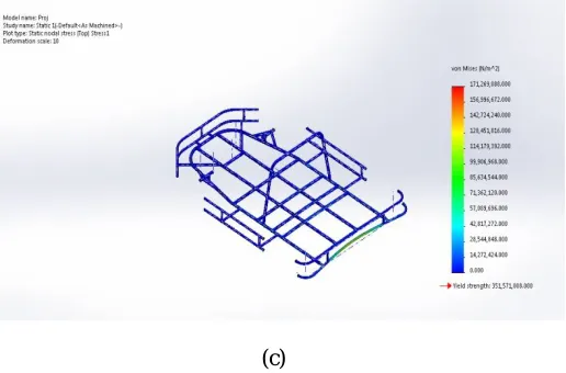
IV. SIMULATION & RESULTS
A. RESULTS
(c)
Fig 3: (a) Frontal Impact Analysis, (b) Side Impact Analysis, (c) Rear Impact Analysis
Table IV: Load & Constraints
Front Impact Side Impact Rear Impact Constraints Rear Bumper Fixed Opposite Bumper Fixed Front Bumper fixed
Load Given 3960N 3960N 3960N
Max. Deflection 2.145mm 2.249mm 2.170mm
Table V: Analysis Details Content Description
Study Name Static 1
Analysis type Static
Mesh type Shell mesh
V. STEERING SYSTEM
A. OBJECTIVE
B. DESIGN
Simplicity and safety were the main design specifications for the vehicle’s steering system. While designing the steering system the constraints that we possessed were center alignment of steering system.
Table VI: Steering Specifications
Description Specification
Inner turning angle 30 deg
Outer turning angle 22 deg
Turning radius 2.5m
Castor angle 12 deg
Camber angle 0 deg
King pin inclination 7 deg
Tie rod length 0.36m
Steer wheel diameter 11 inch
The formulae’s used for steering calculation are:
R = d/2+Lcosec (A/2+B/2)
Where,
R is the turning radius,
L is the length of the cart,
A is the angle of the inside angle of the wheel
B is theangle of the outside wheel
d is the width of the car.
To determine the Ackerman percentage, equation (2) was used. Given that, 100% Ackerman angle is desired, A at 30-degreesand B at 22-degree was the best option.
This gave a turning radius of 3.2m.
Inner and outer turning angle is calculated by the formulae-
Outer angle- tan A = L/(R-d/2) Inside angle- tanB = L/(R+d/2)
Fig 4:Steering Geometry
Therefore our kart does not skid because the inside front wheel is angled just a little more than the outside front wheel.
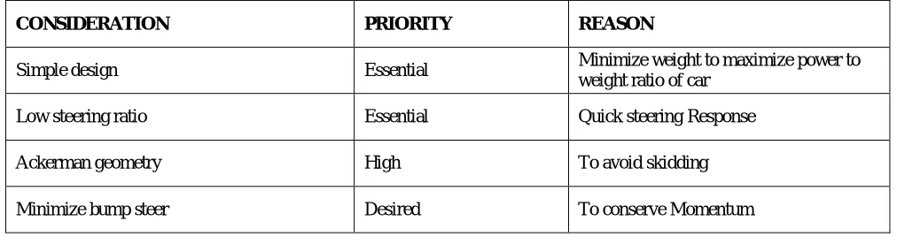
Table VII: Steering Design Considerations
CONSIDERATION PRIORITY REASON
Simple design Essential Minimize weight to maximize power to
weight ratio of car
Low steering ratio Essential Quick steering Response
Ackerman geometry High To avoid skidding
Minimize bump steer Desired To conserve Momentum
VI. DRIVE-TRAIN
A. OBJECTIVE
The drive-train is a very important part of the racing cars, taking into consideration that all of the car’s power is transferred through the drive-train system to the ground.The challenge is to harness the engine’s 3.5 basic horsepower (BHP) and distribute it to the ground in the most efficient way. The drive-train needs to be able to operate in the lowest and highest gear ratios while performing in all of the different aspects of the competition.The goal of the drive train is to transfer power from the engine of the vehicle to the wheels. The power transferred must be able to move the vehicle. Acceleration is also an important characteristic controlled by the drive train. There are several different methods of power transmission that have been used in cars. And also works on infinite no. of gear ratios according to the speed of engine.
B. ENGINE:
series line of engines utilize unique overhead valve (OHV) technology to provide solid performance, cleaner operation and longer life.
Dura bore cast iron cylinder sleeve withstands wear and abuse to provide improved oil control and extended life. Gear driven duraLube splash lubrication system continuously supply oil to all internal parts magneto electric
ignition system delivers quick and dependable start with no maintenance required.
Maxi- clean automotive type pleated paper air filters provide superior protection for longer engine life. Super Lo-Tome muffler reduces noise levels and improves toner quality.
Overhead valve design (OHV) runs cooler and cleaner to deliver more power, longer life and improved fuel economy.
Dual Ball Bearings helps reduce engine and part wear for extended life.
C. ENGINE SPECIFICATIONS
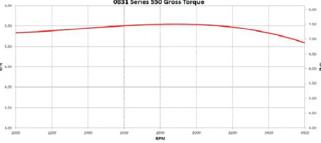
Power, P =2.6 KW Where, P = 2 π NT/60
Max Torque =7.52 Nm@ 3300rpm
Gross torque = 3.5Hp * 5252 (const.) / 3060rpm Where, Gross Torque =5.5 ft-lbs @3060rpm
Fig 5:Engine Torque Curve D. CVT TRANSMISSION SYSTEM:
6.4.1 Chain - Sprocket: No.1 (B/w Motor and CVT)
No of teeth in motor sprocket: 17 teeth No of teeth in Pinion: 13 teeth Ratio: 0.76
6.4.2 Chain - Sprocket: No.2 (B/w CVT and Rear shaft)
No of teeth in Pinion and CVT sprocket: 13
The CVT has a centrifugal clutch that engages at 1400 rpm.
6.4.3 Calculations
1. Motor RPM: 1320 rpm
Power shaft rpm = 1737/22.11 = 78.56 RPM
Speed (Km/h) = Power shaft rpm * * Wheel Dia * 60 /1000 = 78.56*3.14*0.4128*60*10-3 = 6.1 Km/h
2. Motor RPM: 1680 rpm
Wheel diameter: 0.4128m (16 inch) Primary Reduction = 0.76
CVT input RPM = 2210.52 RPM CVT Ratio at 2210.52 RPM: 16.71
Power shaft rpm = 2210.52/16.71= 132.28 RPM
Speed (Km/h) = Power shaft rpm * * Wheel Dia * 60 /1000 = 132.28*3.14*0.4128*60*10-3=10.29 Km/h
3. Motor RPM: 2100 rpm
Wheel diameter: 0.4128m (16 inch) Primary Reduction = 0.76
CVT input RPM=2763RPM
CVT Ratio at 2763 RPM: 10.80
Power shaft rpm = 2763/10.80 = 255.833 RPM Speed (Km/h) = Power shaft rpm * * Wheel Dia * 60 /1000
= 255.833*3.14*0.4128*60*10-3= 19.9 Km/h
4. Motor RPM: 2280 rpm
Wheel diameter: 0.4128m (16 inch) Primary Reduction = 0.76
CVT input RPM=3000RPM
CVT Ratio at 3000 RPM: 8.997 Power shaft rpm = 3000/8.997 = 333.44RPM
Speed (Km/h) = Power shaft rpm * * Wheel Dia * 60 /1000 = 333.44*3.14*0.4128*60*10-3= 25.93 Km/h
5. Motor RPM: 2520 rpm
Wheel diameter: 0.4128m (16 inch) Primary Reduction = 0.76
CVT input RPM= 3315.78PM CVT Ratio at 3315.78 RPM: 6.584
Power shaft rpm = 3315.78/6.584 = 503.61 RPM Speed (Km/h) = Power shaft rpm * * Wheel Dia * 60 /1000
= 503.61*3.14*0.4128*60*10-3= 39.17 Km/h
6. Motor RPM/: 3600 rpm
Wheel diameter: 0.4128m (16 inch) Primary Reduction = 0.76
CVT input RPM= 4736.84 RPM CVT Ratio at4736.84 RPM: 6.33
Power shaft rpm = 4736.84/6.33 = 748.31 RPM
VII. BRAKING SYSTEMS
A. OBJECTIVE
The purpose of the brakes is to stop the car safely and effectively. In order to achieve maximum performance from the braking system, the brakes have been designed to lock up rear wheels, while minimizing the cost and weight.
B. DESIGN
The brake system design includes the double disc at the rear axle to stop the vehicle. It is mounted in the one third part position of the axle with opposing the position of drive train sprocket hence also enables the good balancing requirement.Master cylinder is used at the front near the brake pedal providing the occupant to easily accessible space. The braking effort is 60% on the front. A proper master cylinder bore size was found by doing brake calculations based on the mass, center of gravity, master cylinder volume, weight transfer when the brakes are applied. The construction of the brake is rear hydraulic split. It is actuated hydraulically and the caliper that is used is floating type. The brake calculations are as follows.
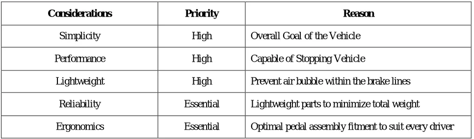
TABLE VIII: BRAKE DESIGN CONSIDERATIONS
Considerations Priority Reason
Simplicity High Overall Goal of the Vehicle
Performance High Capable of Stopping Vehicle
Lightweight High Prevent air bubble within the brake lines
Reliability Essential Lightweight parts to minimize total weight
Ergonomics Essential Optimal pedal assembly fitment to suit every driver
When the brakes are applied the weight is transferred from the rear to the front. There will be a reaction force and inertia force acting on the wheels due to the weight of the vehicle. So there will be an overturning coupleacting at the center. By resolving the horizontal and vertical components acting at the wheels and the center of the vehicle (In our case the brakes are applied at the rear only). So the retardation of the vehicle is calculated.
Where b is the Wheelbase
x = 0.573 m - from front of the rear axle h = 0.3 m - above the ground level.
Coefficient of friction, μ = 0.6 (in limiting case)
Retardation of vehicle,α= 9.3 m/ s2(from the aboveweight transfer formula)
Condition: For velocity of vehicle, v = 60 km/h = 16.67 m/s – The stopping distance and the stopping timecalculation is as follows
Stopping Distance – formula taken from the laws of motion
S= v2/ 2α= 14.28 m
Stopping Time - formula taken from the laws of motion = u/a t = 1.7s
From Newton’s law of motion, we take Braking force required for the vehicle, F = m.α Therefore, F = 150 × 9.3 = 1395 N
And the required Braking torque is calculated using,
Brake Torque= Brake Force × Effective radius ofrotor{(D + d)/4} for dry disc B.T. = 64.7 Nm
Force applied by the driver on the pedal is taken as 100 N (app.) and the pedal ratio is 4:1. The area of the piston of the master cylinder is 1.
Therefore,
Brake pressure = pedal ratio x pedal force / area of the cylinder piston B.P = 5.5Mpa
Appropriate Rotor(Disc),Master Cylinder and Caliper are Chosen nearer the calculated values.
Table IX: Brake Technical Specifications
Description Specifications
Disk Outer Diameter 16 cm
Disk Inner Diameter 2.54 cm
Thickness of Disk 0.5 cm
Brake Pedal Force 10 N
Pedal Ratio 4 : 1
Coefficient of Friction 0.60
Brake line pressure 5.5 MPa
Brake Torque 64.7 Nm
Stopping time 2.8 sec
C. TYRESANDSELECTIONPARAMETERS
TYRE DIMESIONS used in the vehicle
11/7.10-5 (rear) 10/4.50-5 (front)
The type of tire that we are going to use is a radial tire (more properly, a radial-ply tire) is a particular design of vehicular tire (in British English,tire). In this design, the cord plies are arranged at 90 degrees to the direction of travel, or radially (from the center of the tire).
D. CONSTRUCTION PARAMETERS
With only radial cords, a radial tire would not be sufficiently rigid at the contact with the ground. To add further stiffness, the entire tire is surrounded by additional belts oriented closer to the direction of travel, but usually at some "spiral" angle. These belts can be made of steel (hence the term steel-belted radial), polyester, or Aramid fibers such as Twaronor Kevlar.In this way, low radial tires separate the tire carcass into two separate systems:The radial cords in the sidewall allow it to act like a spring, giving flexibility and ride comfort.The rigid steel belts reinforce the tread region, giving high mileage and performance.Each system can then be individually optimized for best performance. Radial tires have different characteristics of springiness from those of bias-ply tires, and a different degree of slip while steering.The steel wires in radial tires become magnetic with use, and as they rotate, an alternating magnetic field is created. It is quite measurable with an EMF meter close to the wheel well when the wheel is rotating and is rich in harmonics up to several hundred hertz.
VIII. SUPPORT COMPONENTS AND PARAMETERS
A. SEAT AND SITTING ARANGEMENT
The seat in this kart is also designed to be very light it is very simple made of plastic material and is attached to the chassis by four points only and can be adjusted in angle of back rest according to the requirement of the drivers comfort the back side angle of the seat is at 17 degrees which is the good position of the drivers body rest according to the ergonomics point of view and is kept almost parallel to the fire wall .the seat implemented in our go kart provides a good combination of weight reduction and ergonomics.
B. ASTHETICS
Aesthetically, the design is improved by the use of more rounded corners than the straight. The unique use of rounded corners allows for a more pleasing look to the vehicle’s body as well as a reduced number of welded joints. The use of continuous bended pipes also reduced the no of joints the lack of sharp edges on the chassis allows for the design of more streamlined body panels which not only look smoother, but may also have a positive effect on the overall aerodynamic drag forces.
C. GROUND CLEARANCE
Standard ground clearance is given for our vehicle such that it prevents any part of vehicle touching the ground (except wheels). Also the ground clearance is taken from the lowest point under the vehicle.
The vehicle contains two jack points situated at the front and rear end of the chassis which has 10 inches of steel tube painted with red color
E. BALLY PAN (FLOOR TRAY)
The bally pan is placed just behind the brake and accelerator pedals as per the rulebook to prevent any foreign particles from entering into the driver’s area as well as in entire vehicle.
F. ERGONOMICS
Ergonomically the kart is build up with proper dimensions. The driver seat is well cushioned and 3 inches away from the firewall. Alignment of the driver seat/driver sitting direction is parallel to vehicle’s longitudinal axis. The driver is well sophisticated to drive a kart without any disturbance.
G. KILL SWITCH
Two Kill switches are provided in our vehicle as a safety to the in case of emergency. One in the reach of the driver and the other for the reach of a Third person.
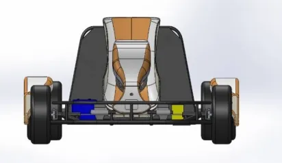
IX. FINAL 3D VIEW
Fig 6: (a)Front View(b) Top View(c) Rear View(d) Orthogonal View
(a) (b)
REFERENCES
[1] Barnard, R. H., Road vehicle aerodynamic design - an introduction, MechAero Publishing, 2001.
[2] Richard Stone and Jeffrey K. Ball, “Automotive Engineering Fundamentals”,Society of Automotive Engineers, ISBN 0-7680-0987-1
[3] L. Chu, et al., "Coordinated Control of Electronic Stability Program and Active Front Steering," Procedia Environmental Sciences, vol. 12, Part B, pp. 1379-1386, 2012.
[4] Z. Gao, et al., "Dynamic Modeling and Steering Performance Analysis of Active Front Steering System," Procedia Engineering, vol. 15, pp. 1030-1035, 2011.
[5] Carroll Smith, “TUNE TO WIN”, Aero Publishers, INC. 1978, ISBN 0-87938-071-3
[6]Warren J.Rowley “Introduction to Race Car Engineering”, Book-1,3rd Edition.ISBN-9780-9734-3200-8
[7] R.S.Khurumi, J.K.Gupta., “A Textbook Of Machine Design”, EURASIA PUBLISHING HOUSE.(PVT).LTDRevised edition 2014,
ISBN-978-81-219-2537-2.
[8]N.Kurumi, R.S.Kurumi., “STRENGTH OF MATERIALS (mechanics of solids)”., S.CHAND&COMPANY PVT.LTD. Revised edition
2013,ISBN-81-219-2822-2
[9]Ibrahim Zeid “Mastering CAD/CAM”., McGraw Hill Education(India)Pvt Limited. Revised edition 2013,ISBN-9780-0712-3933-2
[10]S.S.Rattan, “THEORY OF MACHINES” Fourth Edition., Hill Education(India)Pvt Limited, Revised edition 2014, ISBN-978-93 5134-347-9
[11]PSG College Of Technology “DESIGN DATA Data book of Engineers”, Kalaikathir Achchagam, Coimbatore, ISBN-978-81-927355 04.