ABSTRACT
SIMPSON, CLARENCE ADRIANO. A System for Generating
Device-Specific Action Sequences. (Under the direction of Robert St. Amant)
As computing devices become more varied and complex, it has been shown
that it is useful, perhaps even essential, to begin describing elements of
human-computer interaction in more abstract terms. Much of the literature
has focused on specific cases of interaction involving certain input devices,
tasks, and operating system environments. However, it has thus far been
taken for granted that the mapping between the controls on an input device
and the low-level tasks being executed with the device are an optimal
mapping. We present a system for generating this optimal mapping by
classifying input devices and low-level tasks based on the proposed
taxonomies, then using a knowledge base to determine the efficiency of
using certain classes of input device controls to perform certain classes of
tasks. We also present some preliminary work in the use of user modeling to
account for cognitive and psychological factors such as user control
preference and the relation between action sequence complexity and human
A SYSTEM FOR GENERATING DEVICE-SPECIFIC
ACTION SEQUENCES
by
CLARENCE ADRIANO SIMPSON
A thesis submitted to the Graduate Faculty of North Carolina State University
in partial fulfillment of the requirements for the Degree of
Master of Science
COMPUTER SCIENCE
Raleigh
2003
APPROVED BY:
_________________________ _________________________
Christopher Healey
James Lester
_________________________
Robert St. Amant
BIOGRAPHY
Clarence Adriano Simpson was born on December 26, 1977 in Burlington,
North Carolina to Marie Simpson and the late Clarence Joseph Simpson. He
graduated from Walter Williams High School in 1994. He then proceeded to
North Carolina State University for undergraduate studies and in 2000
graduated Cum Laude with a BS in Computer Science and a minor in
Chemical Engineering. He entered the Computer Science graduate program
at North Carolina State University immediately after the completion of his
undergraduate degree and completed the course requirements for the MS
degree in 2002. In August of 2002, he was finally able to marry his soul
mate, Jamila Smith, whom he met as an undergraduate at NCSU. After a
short hiatus due to financial difficulties, Clarence is finally able to complete
his thesis in 2003 as the last requirement before obtaining his MS degree in
ACKNOWLEDGEMENTS
I have many thanks to hand out to all the people in my life who have shaped
and molded me in one way or another into the person I am today and who
have helped see me through and support me to this point of my education.
First and foremost, thanks to God, without whom everything is meaningless.
To my beautiful wife, Jamila Simpson, thank you for all the loving support
and encouragement (and forceful nudging when I needed it) that you have
been giving me for so long now. I would not have made it this far without
you, and I would definitely not be the person I am today without having
known you. I love you!
To my mother, Marie Simpson, thank you for always thinking I was the best,
for nurturing me, and for teaching me the importance of doing well in school
at an early age.
To my high school math teacher, Jim Smith, I don’t know if you realize how
much you affected my academic career and personal growth. I wish more
high school teachers willing to put forth the effort to teach a class with only
one student in it!
To the Duke Power Foundation and the North Carolina Department of
Veterans’ Affairs, without your scholarships, I likely would not have been
able to afford my college education. Thank you for providing me with this
opportunity.
To Norm Peart, thanks for all of your guidance, encouragement, and for the
life lessons I’ve learned since knowing you. And special thanks for letting
me take a vacation from my duties to finish this paper off!
To my advisor, Rob St. Amant, thanks for being patient with me and my
unusually long time taken to write this thesis. Your advice and direction
were invaluable.
And especially to my father, who long ago gave me that first spark of
TABLE OF CONTENTS
LIST OF TABLES ... vii
LIST OF FIGURES ... viii
1. INTRODUCTION... 1
1.1. Terminology and Overview... 5
2. RELATED WORK ... 8
2.1. Review of User Interface Abstraction ... 10
2.2. Review of Task Analyses and Models ... 12
2.3. Review of Input Device Analyses and Models ... 13
2.4. Review of User Analyses and Models ... 14
2.5. Review of Studies of Task Efficiencies ... 16
3. SYSTEM DESIGN... 19
3.1. Device Taxonomies ... 21
3.2 Task Taxonomies... 26
3.3. User Characterization ... 29
3.4. Knowledge Base... 31
3.5.1. Action Sequence Template Syntax ... 33
3.5.2. Action Sequence Syntax ... 33
4. CASE STUDIES... 35
4.1. Case Study #1 – IBM TrackPoint Mouse: 1-D Positioning... 36
4.2. Case Study #2 – Control Panel: 2-D Orientation... 42
4.3. Case Study #3 – Flightstick: 2-D Positioning... 48
5. FUTURE WORK ... 54
5.1. User Modeling ... 54
5.2. Task Sequences ... 56
5.3. Speed-Accuracy Tradeoff... 57
5.4. Knowledge Base Population... 58
5.5. Muscle Group Influences ... 59
6. CONCLUSION ... 60
LIST OF TABLES
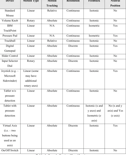
Table 1: Sample Device Classifications... 25
Table 2: IBM TrackPoint mouse taxonomy ... 39
Table 3: 1-D Positioning Action Sequence Template library... 39
Table 4: ER Modifier Rules for Case Study #1... 39
Table 5: Applying ER Modifiers to action sequences in Case Study #1 ... 42
Table 6: Virtual control panel taxonomy... 44
Table 7: 2-D Orientation Action Sequence Template library... 44
Table 8: ER Modifier Rules for Case Study #2... 45
Table 9: Applying ER Modifiers to action sequences in Case Study #2 ... 47
Table 10: CH Products Flightstick taxonomy ... 49
Table 11: 2-D Positioning Action Sequence Template library... 50
Table 12: ER Modifier Rules for Case Study #3... 50
LIST OF FIGURES
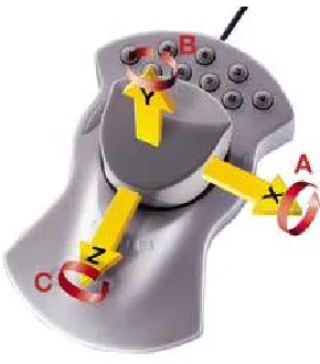
Figure 1: Example of a complex input device with six axes for input... 9
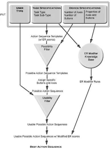
Figure 2: System workflow diagram... 20
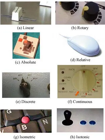
Figure 3: Examples of Axis Properties: ... 24
Figure 4: IBM TrackPoint mouse ... 36
Figure 5: Virtual control panel... 43
Figure 6: Real world control panel of an audio mixing board ... 43
1. INTRODUCTION
A short version of this paper appeared in the Proceedings of the 2003 International
Conference on Intelligent User Interfaces.
The computer was invented to perform complex and repetitive tasks for its operator. Part of the inherent difficulty of designing such a device was that computers operate in a digital universe, while humans operate in our physical universe. Computers and their users have always been in a constant battle to translate elements of our physical universe into the digital realm and vice versa. Without this ability to translate information,
computers are useless.
Since the advent of computing devices, researchers have been studying the best ways to get information into a computer as well as how to get useful information out. This is the fundamental basis for the study of human-computer interaction. Some of the areas of research include input devices, output devices, interface design, task efficiencies, user modeling, and many other more specialized topics. This research will focus on the area of task efficiencies. The work also has an indirect relation to the areas of input device design and user interface design.
device. Although many devices have some similarities, there has been little done to try to classify and quantify these properties.
In recent years, a significant amount of Human-Computer Interaction research has been done in the area of designing optimal user-interfaces for particular tasks and even
automatically generating those interfaces based on the task specifications. However, most of the research that has been done has focused on what kind of widgets appear on screen, where they should be placed, and how they should be used given the standard keyboard-and-mouse paradigm.
It appears that this research is ignoring a fundamental component of the interface. They all assume that whatever input device is used is already mapped to specific low-level actions, such as positioning and selection, in the most optimal manner. These very low-level concepts cannot be ignored when designing interfaces.
informing the computer using the input device that the user wants to perform a particular low-level task). The first two have been studied in great detail, but the latter has been, unfortunately, largely neglected.
Take for example a simple, 2-axis joystick with no buttons. If the user interacting with this device is presented with the task of positioning an object in 2-D space on the screen or some other output device, then it is obvious to have each axis of the joystick mapped to one of the dimensions of the 2-D output space. However, take the same joystick and add a few knobs, sliders, and buttons to the device. Suddenly, it is not so obvious what is the most effective way of performing a 2-D positioning task with the device. An average user may contend that the joystick itself is still the best way to perform the task.
However, we must be careful not to make “obvious” conclusions about device-task mappings which are in fact based on convention. Abstractions such as the taxonomies provided in this paper provide the ability to step back and re-evaluate the way tasks are performed.
With this paper we intend to contribute to the literature by providing:
• An abstract taxonomy of input devices and the individual controls on a device • An abstract taxonomy of low-level tasks which are executed in computing
environments
• A conceptual framework for a system which will calculate the most efficient action sequence for performing a task given a task specification, input device specification, and user characterization.
The taxonomies of input devices and low-level tasks are essential parts of the system as a whole and provide the input required for the system to calculate efficiencies. It will also allow other researchers to draw conclusions about an input device based on an analysis of another device and similarities between the devices provided by the taxonomies.
advantage of a common knowledge base which acts as an accumulation of data about how efficient different device types are at performing different tasks.
1.1. Terminology and Overview
A device refers to any particular input device that is used to interact with a computer. Examples of devices are a flight yoke, a mouse, a keyboard, or any other type of control panel. A device is essentially a collection of controls organized in some logical manner. A control is a particular widget on a given device. Some examples of controls are the Tab key on a keyboard, the left button on a mouse, and the x-axis on a joystick. A virtual axis
is a set of two buttons that is functioning as an axis manipulator. A virtual button is an axis functioning as a button for the purposes of confirmation.
A task is a low-level description of what type of things a user will wish to do in a user interface. A particular task will not vary across platforms, operating systems, or
applications. Tasks are also independent of anything that would be specific to a particular interface such as widgets, menus, and other on-screen controls. An example of a task would be 2-dimensional positioning. This particular task is most often manifested on modern computers in the form of homing a mouse cursor onto a particular point or area on-screen.
button click. An action sequence refers to a continuous sequence of specific primitive actions. Particular axes and buttons are specified in an action sequence. An action
sequence template is a continuous sequence of unspecified axis motions and confirmation steps. Action sequence templates specify the order of axis motion and confirmations, but do not assign particular device controls to be used in the actual action sequence.
The efficiency rating (ER) of a particular action sequence or action sequence template gives a quantitative approximation of how “efficient” that particular action sequence is for completing a given task on a given device. The ER is calculated based on two factors, speed and accuracy, because they are the two most important factors in determining how efficiently a user can accomplish a task.
Each possible action sequence template that can be used to perform a task has a pre-assigned base ER. The base ER is independent of which particular axes and buttons are assigned to the action sequence template. To take into account the effect that assigning particular axes and buttons has on efficiency, ER modifiers are used. ER modifiers are quantitative values that modify the base ER scores of an action sequence based on which particular axes are assigned and the properties of those axes.
The remaining sections of this thesis are as follows: Section 2 covers an overview of past research work in the areas of user interface abstraction, studies of efficiency in
performing tasks, and analyses and models of tasks, input devices, and user characteristics. Section 3 deals with the design of our system including detailed
2. RELATED WORK
Under the broad category of input devices and their efficiency, research has been conducted on how to analyze and improve efficiency with existing devices that are already in commonplace use, such as the keyboard and mouse. Researchers have analyzed more efficient ways to use or alter these devices, such as the split-design ergonomic keyboard or the wheel mouse. They have also studied non-traditional ways of using these devices such as gesture recognition.
There has also been a fairly large amount of research devoted to creating new and
Figure 1: Example of a complex input device with six axes for input
Work in the area of graphical user interfaces is also very commonplace. Many
researchers are studying and designing new menu systems and new ways to give visual or other sensory feedback to the user. Current graphical user interfaces are primarily
platform-dependent, but extensive work has been invested into developing systems to allow the creation of user-interfaces to be as platform-independent as possible.
Studies of device-task efficiency have been largely limited to specific examples of input devices and tasks rather than generalizing into more low level terms. However, much of the existing literature in these areas can provide an important foundation for the design of this system.
The related work can be broken down into five areas of research: user interface
abstraction, task analyses and models, input device analyses and models, user analyses and models, and studies of task efficiencies.
2.1. Review of User Interface Abstraction
In the past, graphical user interfaces have primarily been constrained to having only a few generic types of output devices on which to display the actual interface. However, as computing becomes a more pervasive part of everyday life, the amount of different output devices usable for displaying user interfaces has grown very quickly. To help deal with the issues created by these varying output devices, research has turned to looking at designing user interfaces in a more abstract fashion.
performing the same task on different devices may require very different steps due to the inherent structures of the different input devices. An input device with more controls will likely allow for more possible options to be displayed simultaneously, and thus, will require fewer steps to accomplish a given task.
Puerta and Eisenstein have also proposed a markup language called XIML for abstracting user interfaces away from specific devices or platforms[14]. XIML is an XML-based language for describing interaction data and processes. They propose that XIML fulfills the requirement of allowing user interface designers to easily design cross-platform interfaces by making a distinction between the definition of an interface and the
rendering of an interface. Using XIML interface designers can focus on the real issues of the interface and human-computer interaction rather than the minor nuances introduced by porting the interface to multiple platforms.
2.2. Review of Task Analyses and Models
The literature provides a starting point for classifying various types of tasks that are performed with input devices. Unfortunately, many of the task taxonomies that are already presented are specialized for specific applications such as image browsing[13], information visualization[15], and even controlling musical instruments[12]. These specialized taxonomies can give some insight into designing a much more generalized taxonomy that is independent of the application.
Buxton proposes a more generalized taxonomy which categorizes tasks that can be used for the analysis and evaluation of input devices: pursuit tracking, target acquisition, freehand inking, tracing and digitizing, constrained linear motion, and constrained
circular motion[1]. This particular taxonomy is much closer to what this system attempts to accomplish. Buxton manages to abstract low-level tasks outside of the application environment to create a taxonomy that is useful in any problem instance.
structure of a task matches the control structure of the input device being used to perform the task.
2.3. Review of Input Device Analyses and Models
From the beginnings of human-computer interaction, researchers have been studying how to identify, classify, and organize information about input devices and about how to select the appropriate input device to use to perform a particular task. Some of the earliest research involving interaction with computer graphics systems laid some of the
foundations for describing what kind of actions a particular device was capable of[9]. However, in these early stages many distinctions were not made between input devices as long as they were capable of the same function. This lack of efficiency and usability analysis resulted in treating a positioning task with an isotonic joystick the same as performing a positioning task with a trackball, for example.
Buxton was one of the first to distinguish between input devices based on some basic physical characteristics[2]. He presented an input device taxonomy that classified devices based on the number of dimensions of movement and the property being measured:
Card, Mackinlay, and Robertson expanded upon this basic taxonomy by introducing several new ideas such as mapping functions from input device to output device, input device footprints, a distinction between linear and rotary motion, and the effect of using different muscle groups to manipulate a device[4]. They also presented a more
generalized categorization for describing what property a device senses. In their taxonomy, the property a device measured had three attributes. The property was measured either in a linear or rotary fashion, it measured either position or force, and it measured either absolutely or relatively. Through this input device design space most of the devices available at the time could be easily classified and most distinctions between devices that would be obvious to the casual observer would be represented in some fashion through their taxonomy.
There has also been considerable research in the area of input devices and their efficiency and usability that has largely revolved around specific input devices. The results that have been found from these studies are an excellent foundation for the generalization of input devices that will be attempted in this paper. We will attempt to generalize differences between input devices by analyzing specific device properties, such as a particular device control being linear rather than rotary. Research that has been done on specific cases of these input device differences is essential for forming our generalized rules.
2.4. Review of User Analyses and Models
of the psychological aspects of user analysis, such as the mental process of inquiry and how people tend to absorb information given to them through user documentation. They also studied how tasks are affected by the level of user expertise, and the desire to tailor information to suit a particular user’s goals or attributes.
Kamm, et al presented results from a study of the effects of tutorials and training on the efficiency of users interacting with a spoken dialogue system[11]. They found that as little as four minutes of training and tutorials made a significant difference in the efficiency of novice system users. In fact, after the tutorials, the novice users had
completion times and satisfaction ratings comparable to expert users. Although this study is system-specific, it can lead us to speculate that investing even a small amount of time in training novice users can be well worth the effort in closing the gap between novice and expert users.
familiarity with content, and query complexity. They also identified visual representations which were best suited to each stereotype. The user signature is essentially a condensed history of the user’s interaction with the system. The system can then use this information to infer some things about the user’s preferences. Finally, the system model is the user’s perception of the database. This can be exploited by the system to hide information that the user is not interested in while focusing on data that is important to the user. This kind of user model provides a good framework towards creating a user model to be used in generating action sequences.
2.5. Review of Studies of Task Efficiencies
Studies in the area of task efficiencies are essentially studies into the interrelationship between input devices, tasks, and users. The literature has shown that even slight
alteration in any portion of these three variables can have a measurable impact on a user’s efficiency at performing a task with an input device.
Some clarification may be required to further define what is meant by efficiency.
Efficiency can be considered to be a combination of measurements in the areas of speed
One of the foundational papers in input design presented the concept of Fitts’ Law and how it affected a user’s efficiency at performing a particular task[5]. Card shows that one of the most fundamental tasks that is performed by a user to provide is moving the user’s hand to a particular target. Fitts’ Law predicts that the time required to move to the target is proportional to the logarithm of the distance to the target divided by the width of the target. This result presented input device designers and user interface designers with a benchmark to use on their designs. If they were planning on moving a target twice as far away from some start position, they knew the target must be made twice as large to maintain the same level of efficiency.
Jacob, Sibert, McFarlane, and Mullen, presented research into how the user, input device, and task are all closely interrelated and all have an impact on user performance[10]. In their studies, they found that users were much more efficient in their tasks when the perceptual structure of the task matched the control structure of the device being
manipulated. Results such as this can be used as a basis for forming some of this system’s ER Modifier Rules.
One of the most useful and practical efficiency models is the keystroke level model
3. SYSTEM DESIGN
Very little work has been done in researching the best way to perform a low-level task on a given input device independent of platform, operating system, and application. So here is presented a proposal for a system that attempts to produce the best (in terms of
usability as well as efficiency) possible action sequence for a particular user to perform a particular task on a particular device. The overall workflow of the system is shown in Figure 2.
3.1. Device Taxonomies
There are several different characteristics that define a particular input device. An input device can have any of a number of different controls on the device itself. There may be joysticks, buttons, knobs, sliders, switches, wheels, touchpads, and other non-standard controls. However, all of these controls can essentially be characterized as either axes or buttons.
All controls can be described as a set of axes in some number of dimensions except for a standard button. A standard button is a button which is always either in an on position or an off position (i.e. – no pressure sensitivity) and will return to the off position in its neutral state.
There are several different properties that characterize the axes and help distinguish between obviously different controls. These properties are: Motion Type, Motion Tracking, Resolution, Control Binding, Control Separation, Feedback, Neutral Position, Dead Zone Size, and Physical Axis Length.
• Motion Tracking – This describes how the motion is measured by the axis. Axes that measure motion by the position along a finite axis use absolute tracking. Axes that measure motion based on the distance traveled from the last position that was
measured to the current position are said to have relative tracking. (e.g. – a slider uses absolute tracking, a mouse uses relative tracking). Motion tracking does not apply to isometric controls because there is no motion involved in their use.
• Resolution – This describes the precision used when taking the measurements. A device that measures in a stepwise fashion uses discrete resolution. A device that measures with infinite precision uses continuous resolution. Although no digital device truly has continuous resolution, the steps are small enough such that they operate essentially as a continuous device. (e.g. – A switch has discrete resolution, a slider has continuous resolution)
• Control Binding – This refers to where the controls are physically placed on the device. When one control is placed on another control, the operation of one control can interfere with and cause error in the measurement of the other control when they are used simultaneously. This is also referred to in some of the literature as integral
vs. separable.
• Control Separation – This refers to the physical distance between controls.
Obviously the further apart controls are, the more time it will take the user to move between the controls. However, if the controls are too close together, it may also introduce an element of user error in the activation of the controls.
measures the position of some physical element of the control is said to be isotonic. (e.g. – one of IBM’s TrackPoint buttons is isometric, a joystick is isotonic)
• Neutral Position – An axis has a neutral position if the axis will always return to a set position when a user releases the axis. (e.g. – a slider control has no neutral position because it will stay at whatever value it is currently at when you release it, but most joystick controls do have a neutral position at the center position of the joystick) • Dead Zone Size – An axis’ dead zone is the amount of distance around an axis’
neutral position where no change is registered. Some axes have no dead zone. Dead zones can help to compensate for user error that may be introduced by control placement issues.
• Physical Length of Axis – This describes the physical distance from one end of an axis to the other. Two sliders that might otherwise be identical may be better suited for different tasks due to the different physical lengths of their axes.
Figure 3: Examples of Axis Properties:
Device Motion Type Motion Tracking
Resolution Feedback Neutral Position Standard
Mouse
Linear Relative Continuous Isotonic No
Volume Knob Rotary Absolute Continuous Isotonic No IBM
TrackPoint
Linear N/A Continuous Isometric Yes
Pressure Pad Linear N/A Continuous Isometric Yes
Trackball Linear Relative Continuous Isotonic No Digital
Gamepad
Linear Absolute Discrete Isotonic Yes
Slider Control Linear Absolute Continuous Isotonic No Input Selector
Dial
Rotary Absolute Discrete Isotonic No
Joystick (e.g. – Microsoft Sidewinder) Linear (some may have additional rotary axes)
Absolute Continuous Isotonic Yes
Tablet w/o pressure detection
Linear Absolute Continuous Isotonic No
Tablet with pressure detection
Linear Absolute Continuous Isotonic (x and y axes) and Isometric (z
axis)
No (x and y axis) and Yes
(z axis)
Virtual Axis (i.e. – two buttons being
used as an axis)
Linear Absolute Discrete Isotonic Yes
On/Off Switch Linear Absolute Discrete Isotonic No
There is also a special class of axes and buttons referred to as virtual axes and virtual buttons. These axes and buttons do not exist as such on an input device. Rather, a virtual axis is a set of two buttons being used as an axis. Since the user can always move in two directions along an axis, each of the two buttons can represent moving along the axis in one of the directions, thus simulating a standard axis manipulation.
Likewise, a virtual button is an axis being used as a button. Since buttons are primarily used as confirmation steps, an axis can easily be implemented as a confirmation step by triggering the confirmation whenever a certain threshold along the axis is crossed. This would enable a device with multiple axes but no buttons to perform various tasks by having the user “flick” an axis as the confirmation step.
It should also be fairly obvious that virtual axes and buttons are not very efficient. Axes were not designed to function as buttons and buttons were not designed to function as axes. Therefore, virtual axes and buttons should typically only be used when no true buttons or axes are available to be used to accomplish a given task.
3.2 Task Taxonomies
Rotating a 2-dimensional object 120 degrees clockwise on an output device is an example of a task. Going to the File menu and selecting the Save as... menu item is not an example of a task because it is operating system and application-specific. Instead, it would be described as a 2-dimensional positioning task to place the cursor over the File menu, followed by a confirmation task to click and drop down the File menu. Then, a second 2-dimensional positioning task to place the cursor over the Save as... menu item, followed by a second confirmation task to finally select the menu item and complete the sequence of tasks.
We will not be dealing with task sequences at this point, although it is a definite future research interest. The efficiency of a single task may be dependent on other tasks that must be performed within the sequence. However, for the purposes of this paper, we will only be considering single tasks.
Due to the low-level nature of task descriptions, they can all be broken down into only three categories of tasks. Each category may also have sub-categories that further describe the specifics of that particular task.
• Orientation – Orientation can be 2 or 3-dimensional. Rotating a box clockwise on-screen is an example of 2-dimensional orientation. Specifying a virtual camera angle using a viewpoint from the camera itself is 3-dimensional orientation because the camera can be rotated along any of the 3 dimensional axes.
• Confirmation – Confirmation is actually an essential action that is used in all other tasks, however, it may also be classified as a task in itself. For example, a screen that says “Press any key to continue” would not require any selection, positioning, or orientation, but some form of confirmation must be performed. Typing is a series of confirmation steps because there are no axes involved on the device.
All other “tasks” that would be performed are actually a slightly different representation of one of the four above categories, or a task sequence. A quantification task is really just a 1-dimensional positioning task. A path specification task is a sequence of positioning and orientation tasks. Text input is really just a series of confirmation tasks whose efficiency is determined by control separation. Single target selection is generally a positioning task or, if enough buttons are available to accommodate all possible choices, a single confirmation task. Multiple target selection can be a sequence of single target selections or in some cases an area/volume selection task, which can again be broken down into multiple positioning and confirmation tasks.
something at or rotate something to. Some of the user’s cognitive processes are dependent on the particular interface and not on these low-level tasks.
3.3. User Characterization
While the information that needs to be gathered about the device and task are clearly described and categorized in the Device Taxonomies and Task Taxonomies sections, the information about the user is a little more complex and more difficult to accurately depict. The type of user will determine things such as what type of action sequences the user will feel more comfortable with, whether the user is concerned with speed above all other factors or if the user is more concerned about being able to remember how to perform a particular task, and if it will be intuitive for the user to understand how to perform a task using an action sequence.
In contrast, a novice user would be much more likely to navigate through a system of menus and on-screen prompts to accomplish what needed to be done. In a typical
Windows-style interface this would usually involved a 2-dimensional positioning task to activate a drop-down menu, followed by one or more additional 2-dimensional
positioning tasks to navigate any possible sub-menus and select the desired menu item. This would require much more time, but if the menu system is well designed and logically organized, the novice user would need very little prior knowledge and would also not need to retrieve an obscure action sequence from memory.
Of course, there are many different types of users with many different preferences and priorities for how they do their work. Ideally, it would be great to classify all the different user types or perhaps even have “user properties” with quantitative values associated with particular user traits. This would allow for very in-depth customization of action
sequences to users.
3.4. Knowledge Base
The system’s knowledge base consists of two pieces of pre-existing knowledge. There is an action sequence database that lists all possible action sequence templates that can be used to perform a particular task. Since there is a finite limit to the number of
combinations of sequences of arbitrary axes and buttons that make sense to perform a task, this database will be relatively small.
In addition, the system will contain an ER Modifier Knowledge Base. This knowledge base will consist of a set of ER Modifier Rules. Each rule will determine how the base ER of an action sequence will be modified to account for the specific properties of the axes being used to perform the selected task.
Task sub-category will have no effect on which ER Modifier rules are used because a task is still following the same fundamental concept as long as the main task category remains the same. If an axis with a certain property is slow and inaccurate in 2-D positioning, the same will be true in 3-D positioning.
3.5. System Flow
that particular task. In addition, it will obtain each action sequence template’s base ER score from its database.
The action sequence templates will then be fed into a possibility filter. This filter simply eliminates any action sequence templates that are physically impossible given the number of axes and buttons on the device. For example, a 3-D positioning action sequence
template may require three different axes. If the specified device only has two axes on it, then this template is physically impossible.
Once the possible action sequence templates have been identified, all combinations of specific buttons and axes are assigned to the templates. Each action sequence template will typically generate several action sequences once all the different buttons and axes are assigned. This results in a large list of possible action sequences.
All of the possible action sequences are then fed into the usability filter. As described above, this filter will eliminate some action sequences based on the specified user type. The usability filter will then output a list of usable possible action sequences.
the rules from the knowledge base apply to the action sequence. For each rule that applies, the ER score for that action sequence will be modified.
Once all ER scores are modified, the system is left with a final list of action sequences all with their final modified ERs. At this point, the system simply chooses the action
sequence with the lowest modified ER. That action sequence is the best action sequence to perform the specified task using the specified device.
3.5.1. Action Sequence Template Syntax
Action Sequence Templates are specified in the form:
a|b|c|d…
where each letter represents a certain number of axes to manipulate and each vertical bar ‘|’ represents a confirmation step. Thus, 2|1| represents a 2-axis manipulation followed by a confirmation step, another 1-axis manipulation, and a final confirmation step. Note that since these are templates, specific axes and buttons are not assigned to these action steps.
3.5.2. Action Sequence Syntax
Action Sequences are specified in the form:
where the A or B specifies whether the control is an axis or a button and the i,j,k,…
specifies which specific axis or button is to be used. These axis and button numbers are assigned arbitrarily at the beginning of an analysis, but must remain consistent
4. CASE STUDIES
In this section we will provide real-world examples of how this system might be used and what results might be obtained. However, as mentioned in previous sections, the
knowledge base component of the system, which is a vital piece of the process, is currently empty due to the lack of experimental data to draw on. Section 5.4 briefly discusses some of the work required to populate this knowledge base with usable data.
In the meantime, for the sake of more lucid examples, we will be creating somewhat arbitrary knowledge base values. We use the phrase “somewhat arbitrary” because the values will be correct in terms of magnitude (e.g. – the ER modifier value for a rotary control performing a rotary task will be less than that of a linear control performing a rotary task), however actual numerical values will be selected arbitrarily within magnitude bounds. These values will be presented at the beginning of each case study and will be referenced throughout the example.
In each of the case studies, the ER modifier rules will apply additive modifiers to the base ERs. However, through experimental study, it may prove that certain ER modifier rules should be multiplicative, exponential, or even use some polynomial formula for
determining how the base ERs are affected by certain axis properties. The system is designed to be able to accommodate these changes if necessary.
The examples provided were selected primarily for the sake of simplicity. The
and thus the number of possible action sequences increases exponentially as the number of possible axes and buttons increases. Therefore, only certain relatively simple situations will be worked through in this paper although the principles certainly apply to larger scale problems.
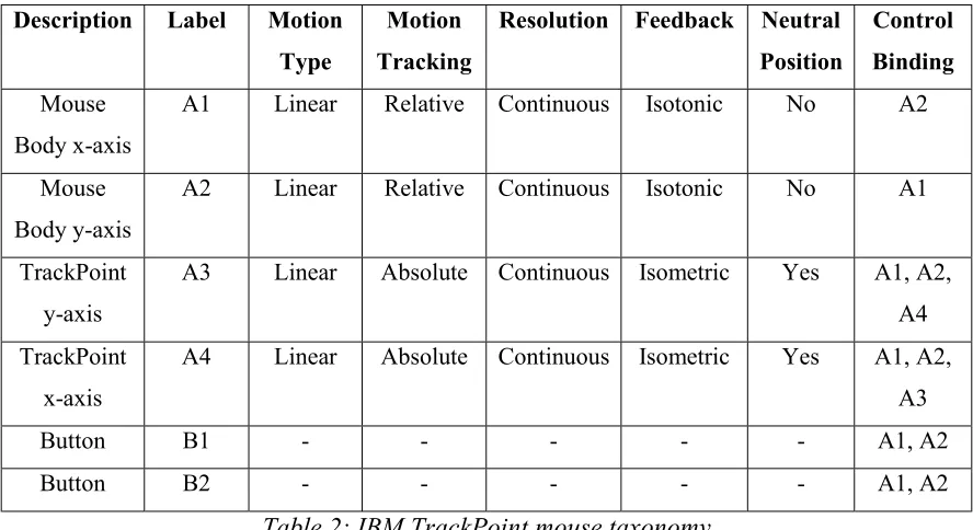
4.1. Case Study #1 – IBM TrackPoint Mouse: 1-D Positioning
We will begin our case studies by looking at the very simple case of using a mouse to perform a 1-dimensional positioning task. We have chosen a simple task because we will perform a more realistic quantitative study of the ER values. However, ER Modifier values are still unable to be calculated due to missing experimental data. Therefore, we will only be doing calculations of the base ER values.
To calculate the base ER values, we need to examine all of the possible action sequence templates for the task type and make separate calculations for each template. In this simple example, there is only one action sequence template, 1|, a single axis motion followed by a confirmation step. Our base ER will essentially represent the average amount of time required to perform a single axis motion followed by a confirmation step.
To apply actual numbers to the calculations, we will need to make a few assumptions about our system setup as follows: The output display is a 17-inch monitor set to a
display resolution of 1024 x 768. The control-to-display ratio is 1:3, meaning that moving the mouse 1 inch will cause an interpreted motion of 3 inches on the display. The motion on the mouse as well as the display will be horizontal. The on-screen mouse pointer will always be centered prior to beginning a task. There will be a random distribution of target points for our 1-dimensional positioning task. The width of the target point will be the approximate width of a standard Microsoft Windows OK button, or about 1 inch.
With this data, we now have enough information to make a calculation of the average amount of time required to perform this task. We will be using a simple version of Fitts’ Law which is as follows:
T = k log2(D/W + 0.5)
T is the time required for the motion, D is the distance to the target, W is the width of the target, and k is an empirically calculated constant. In this case we will be using a value of
k = 200 msec. Using this formula and our assumed information, we calculate that the average time required for this task, and our base ER, is 572 msec.
The IBM TrackPoint mouse is essentially a standard two-button mouse with a very small isometric joystick attached to it. This constitutes a total of four axes and two buttons.
For this example the user characterization will be “expert”. This means that no possible action sequences will be eliminated because of the usability filter.
Description Label Motion Type
Motion Tracking
Resolution Feedback Neutral Position
Control Binding
Mouse Body x-axis
A1 Linear Relative Continuous Isotonic No A2
Mouse Body y-axis
A2 Linear Relative Continuous Isotonic No A1
TrackPoint y-axis
A3 Linear Absolute Continuous Isometric Yes A1, A2,
A4
TrackPoint x-axis
A4 Linear Absolute Continuous Isometric Yes A1, A2,
A3
Button B1 - - - - - A1, A2
Button B2 - - - - - A1, A2
Table 2: IBM TrackPoint mouse taxonomy
Action Sequence Template Base ER Expert Only?
1| 572 No
Table 3: 1-D Positioning Action Sequence Template library
Positioning ER Modifier Rule ER Modification Formula
Axis Motion Type = Linear Modified ER = Base ER
Axis Motion Type = Rotary Modified ER = Base ER + 100
Axis Motion Tracking = Absolute Modified ER = Base ER
Axis Motion Tracking = Relative Modified ER = Base ER + 100
Axis Resolution = Continuous Modified ER = Base ER
Axis Resolution = Discrete Modified ER = Base ER + 400
Axis Feedback = Isotonic Modified ER = Base ER
Axis Feedback = Isometric Modified ER = Base ER + 100
Axis Neutral Position = Yes Modified ER = Base ER + 100
Axis Neutral Position = No Modified ER = Base ER
Confirmation Step bound to manipulated axis Modified ER = Base ER + 250
All necessary input data is now available so we begin the first step in the process. Since this is a 1-dimensional positioning task, we consult the knowledge base’s action sequence template library to find all possible action sequence templates for 1-dimensional
positioning tasks. In this case we find that there is only one (Table 3).
The possibility filter automatically rules out any action sequence templates which are physically impossible given the input device. The only possible action sequence template is 1| which requires only one axis and a confirmation step. Since the mouse has the controls that meets these requirements, the action sequence template does not need to be eliminated.
The next step involves assigning all of the possible axis and button combinations to the action sequence templates. The 1| template yields the following action sequences:
A1B1, A2B1, A3B1, A4B1 A1B2, A2B2, A3B2, A4B2
Next, we examine each of the possible action sequences in turn and determine which of the ER Modifier Rules apply in each instance. The first ten ER Modifier Rules are all axis property rules. The ER of the action sequence will be modified by an axis property rule for each instance of an axis with that particular property in the sequence. However, since each action sequence only has one axis manipulation, it is not necessary to be concerned with multiple instances of axis properties in this example.
There is also an ER Modifier Rule which states that if the confirmation step is bound to one of the manipulated axes that 250 is added to the action sequence’s ER. Therefore, each of the action sequences utilizing A1 or A2 will have this rule apply because the confirmation step buttons B1 and B2 are both bound to A1 and A2.
All of the final modified ER scores are displayed below. The chart shows that the action sequences A3B1, A4B1, A3B2, and A4B2 all tie for having the lowest Modifier ER. This is our metric for determining the best action sequence for performing this task, so any of the four action sequences can be considered the best possible way to perform a
Action Sequence Base ER Axis Property Modifiers
Confirmation Step Binding
Modifiers
Modified ER
A1B1 572 100 250 922
A2B1 572 100 250 922
A3B1 572 200 0 772
A4B1 572 200 0 772
A1B2 572 100 250 922
A2B2 572 100 250 922
A3B2 572 200 0 772
A4B2 572 200 0 772
Table 5: Applying ER Modifiers to action sequences in Case Study #1
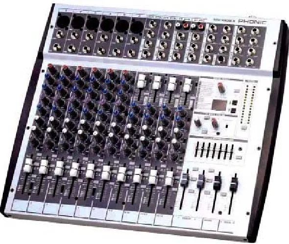
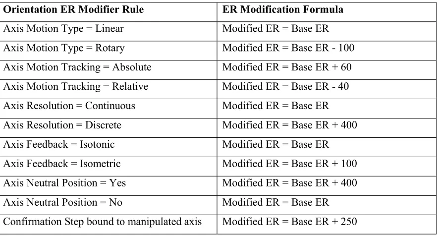
4.2. Case Study #2 – Control Panel: 2-D Orientation
In this example we will be examining the best way to perform a 2-dimensional
orientation task on a control panel interface. For the sake of simplicity, we will be using a virtual control panel with only a small number of controls on the panel. However, the techniques used and results obtained can easily be translated into a more real-world environment with many more controls.
Figure 5: Virtual control panel
Figure 6: Real world control panel of an audio mixing board
Table 6 summarizes the taxonomy of the virtual control panel. Table 7 summarizes the knowledge base’s Action Sequence Template library for 2-dimensional orientation. Table 8 summarizes the knowledge base’s ER Modifier Rules that will be used in the working of this example.
Description Label Motion Type
Motion Tracking
Resolution Feedback Neutral Position
Control Binding
Pan Dial A1 Rotary Absolute Continuous Isotonic No None
Volume Slider
A2 Linear Absolute Continuous Isotonic No None
Channel Dial
A3 Rotary Absolute Discrete Isotonic No None
Button B1 - - - None
Table 6: Virtual control panel taxonomy
Action Sequence Template Base ER Expert Only?
1| 1000 No
Orientation ER Modifier Rule ER Modification Formula
Axis Motion Type = Linear Modified ER = Base ER
Axis Motion Type = Rotary Modified ER = Base ER - 100
Axis Motion Tracking = Absolute Modified ER = Base ER + 60
Axis Motion Tracking = Relative Modified ER = Base ER - 40
Axis Resolution = Continuous Modified ER = Base ER
Axis Resolution = Discrete Modified ER = Base ER + 400
Axis Feedback = Isotonic Modified ER = Base ER
Axis Feedback = Isometric Modified ER = Base ER + 100
Axis Neutral Position = Yes Modified ER = Base ER + 400
Axis Neutral Position = No Modified ER = Base ER
Confirmation Step bound to manipulated axis Modified ER = Base ER + 250
Table 8: ER Modifier Rules for Case Study #2
All necessary input data is now available so we begin the first step in the process. Since this is a 2-dimensional orientation task, we consult the knowledge base’s action sequence template library to find all possible action sequence templates for 2-dimensional
orientation tasks. In this case we find that there is only one (Table 7).
From this we can also see that the situation may arise where it is physically impossible to perform a task with a particular device. In the example of 2-dimensional orientation, a trivial case with no possible action sequence templates is a device with only a single button. Since there is no axis to manipulate, the task cannot be performed.
A device consisting of only two buttons is also incapable of performing the task.
Although the two buttons can be used as a virtual axis, it then leaves no remaining button to use for the confirmation step. So, we can see that the minimum controls necessary to perform a 2-dimensional orientation task is either three buttons or a combination of one axis and one button.
The next step involves assigning all of the possible axis and button combinations to the action sequence templates. The 1| template yields the following action sequences:
A1B1, A2B1, A3B1
Now that we have obtained our list of possible action sequences, we need to send the list through the usability filter to eliminate any choices that are not suitable for the user type. In this example, the user type is expert, so all action sequences will be available. Each of these action sequences start with a base ER score of 1000.
axis property rules. The ER of the action sequence will be modified by an axis property rule for each instance of an axis with that particular property in the sequence. However, since each action sequence only has one axis manipulation, it is not necessary to be concerned with multiple instances of axis properties in this example.
There is also an ER Modifier Rule which states that if the confirmation step is bound to one of the manipulated axes that 250 is added to the action sequence’s ER. In this example, B1 is not bound to any of the axes. Therefore, this ER Modifier Rule does not apply to any of the action sequences.
All of the final modified ER scores are displayed below. The chart shows that the action sequence A1B1 has the lowest Modifier ER. This is our metric for determining the best action sequence for performing this task, so therefore the A1B1 action sequence can be considered the best possible way to perform a 2-dimensional orientation task on our virtual control panel.
Action Sequence Base ER Axis Property
Modifiers
Confirmation Step Binding
Modifiers
Modified ER
A1B1 1000 -40 0 960
A2B1 1000 60 0 1060
A3B1 1000 360 0 1360
4.3. Case Study #3 – Flightstick: 2-D Positioning
In this example we will be examining action sequences for performing a 2-dimensional positioning task on a CH Products Flightstick joystick. The Flightstick has three axes and two buttons. The main joystick component itself is a 2-axis control with both of the buttons attached to it. There is also a small 1-axis throttle control slider to the side of the joystick itself.
The user characterization for this example will be a “novice”. This means that action sequences that are obscure or non-intuitive, and are thus designated as “Expert only”, will not be available as a possible action sequence for this user. This is a qualitative statement and thus, no exact definition can be used. However, some basic principles of human-computer interaction, such as mapping between input and output spaces, can be applied.
Figure 7: CH Products Flightstick
Description Label Motion Type
Motion Tracking
Resolution Feedback Neutral Position
Control Binding
Joystick y-axis
A1 Linear Absolute Continuous Isotonic Yes A2
Joystick x-axis
A2 Linear Absolute Continuous Isotonic Yes A1
Throttle control
A3 Linear Absolute Discrete Isotonic No None
Thumb button
B1 - - - - - A1, A2
Trigger button
B2 - - - - - A1, A2
Action Sequence Template Base ER Expert Only?
1|1| 1000 Yes
2| 750 No
Table 11: 2-D Positioning Action Sequence Template library
Positioning ER Modifier Rule ER Modification Formula
Axis Motion Type = Linear Modified ER = Base ER
Axis Motion Type = Rotary Modified ER = Base ER + 100
Axis Motion Tracking = Absolute Modified ER = Base ER
Axis Motion Tracking = Relative Modified ER = Base ER + 100
Axis Resolution = Continuous Modified ER = Base ER
Axis Resolution = Discrete Modified ER = Base ER + 400
Axis Feedback = Isotonic Modified ER = Base ER
Axis Feedback = Isometric Modified ER = Base ER + 100
Axis Neutral Position = Yes Modified ER = Base ER + 100
Axis Neutral Position = No Modified ER = Base ER
Confirmation Step bound to manipulated axis Modified ER = Base ER + 250
In “2|” Action Sequence Template, both axes are bound to each other
Modified ER = Base ER - 300
Table 12: ER Modifier Rules for Case Study #3
All necessary input data is now available so we begin the first step in the process. Since this is a 2-dimensional positioning task, we consult the knowledge base’s action sequence template library to find all possible action sequence templates for 2-dimensional
The possibility filter automatically rules out any action sequence templates which are physically impossible given the input device. In this case, the templates are 2| and 1|1|, requiring at least two and one axis respectively. Our input device has three possible axes, so no templates are filtered out during this step.
The next step involves assigning all of the possible axis and button combinations to the action sequence templates. The 2| template yields the following action sequences:
A1A2B1, A1A3B1, A2A3B1,
A1A2B2, A1A3B2, A2A3B2
The 1|1| template yields these action sequences:
A1B1A1B1, A1B1A2B1, A1B1A3B1,
A2B1A1B1, A2B1A2B1, A2B1A3B1,
A3B1A1B1, A3B1A2B1, A3B1A3B1,
A1B2A1B2, A1B2A2B2, A1B2A3B2,
A2B2A1B2, A2B2A2B2, A2B2A3B2,
A3B2A1B2, A3B2A2B2, A3B2A3B2
Only” will be eliminated. In some cases, individual action sequences will be tagged as “Expert Only” due to some requirement met by the specific axes and buttons selected. In other cases, the structure of the action sequence template itself can cause itself to be an “Expert Only”. In this particular situation the action sequence template is tagged “Expert Only”, so the entire second set of action sequences can be eliminated. This leaves us with the six action sequences obtained from the 2| template. Each of these action sequences start with a base ER score of 750.
Next, we examine each of the possible action sequences in turn and determine which of the ER Modifier Rules apply in each instance. The first ten ER Modifier Rules are all axis property rules. The ER of the action sequence will be modified by an axis property rule for each instance of an axis with that particular property in the sequence.
For example, one of the ER Modifier Rules states that if an axis being used has a neutral position, that on average that will add 100 to the ER of the action sequence per instance. So, the action sequence A1A2B1 would add 200 to its ER because A1 and A2 both have a neutral position. However, A1A3B1 would only add 100 to its ER because A3 does not have a neutral position. This kind of logic continues throughout the remainder of the axis property ER Modifier calculations.
and A2 because both buttons are located on the joystick proper. We can also note that at least one of A1 and A2 is present in each of the six possible action sequences. Thus, each of the six action sequences will have 250 added to their ER score.
Finally, the last rule states that if an action sequence is derived from the 2| action
sequence template and that both axes are bound to each other that we should subtract 300 from the ER. So, since A1 and A2 are bound to each other, the A1A2B1 and A1A2B2
action sequences will both have 300 subtracted from their ER.
All of the final modified ER scores are displayed below. The chart shows that the action sequences A1A2B1 and A1A2B2 are both tied for having the lowest Modifier ER. This is our metric for determining the best action sequence for performing this task, so therefore either of these action sequences could be considered the best possible way to perform a 2-dimensional positioning task on a CH Products Flightstick.
Action Sequence
Base ER Axis
Property Modifiers Confirmation Step Binding Modifiers 2| Axis Binding Modifiers Modified ER
A1A2B1 750 200 250 -300 900
A1A3B1 750 500 250 0 1500
A2A3B1 750 500 250 0 1500
A1A2B2 750 200 250 -300 900
A1A3B2 750 500 250 0 1500
A2A3B2 750 500 250 0 1500
5. FUTURE WORK
The current state of this system still leaves much to be expanded on although the internal framework is set in place. Through the use of a knowledge base containing various rules and efficiency measures, the system is scalable to suit any particular purpose or to provide large-scale analyses of a wide range of input devices and their suitability to various tasks. Much of the information that would go into the knowledge base would have to be determined through experimentation.
5.1. User Modeling
The user component of the system can be improved upon by taking into account various cognitive and learning models as well as psychological research. Although much of the research in these areas has focused on particular user interfaces, some of the results can still be applied to these low-level tasks.
the device control and the task being performed. These users are willing to sacrifice efficiency and speed for ease of use.
A user’s level of expertise may not necessarily be assigned on a user level. Users may possibly have a task-specific level of expertise. This can most often occur when users perform different tasks at greatly varying levels of frequency. So if a user performs task
A 95% of the time that he is using a particular input device and task B the other 5% of the time, it is very likely that his level of expertise in performing task A is greater than his level of expertise in performing task B. This result is expected because a user would not want to devote a large portion of time to go through an expert-level learning curve for a task that is only rarely performed.
The previous example also shows another point that users may have many varying degrees of expertise in between “complete novice” and “expert”. For these situations more research needs to be done to try and quantify what types of action sequences a particular user prefers in terms of action sequence length as well as action sequence complexity or obscurity. There appears to be some relation between the frequency of performing a particular task and the user’s level of expertise and subsequently what kind of action sequence would be preferred, but more conclusive evidence is needed.
processes of inquiry, the effect of user expertise, and tailoring information to suit a particular user’s goals or attributes. Papers such as this would be vital in providing a more thorough model of users for this system.
5.2. Task Sequences
Another area that has potential for future work is the area of task sequences. The current system focuses on the most efficient way to perform a single task with no knowledge of previous or future tasks. By taking into account other tasks that will be performed before or after the current task, or by analyzing frequently performed tasks the system can provide new levels of complexity that are necessary for real-world applications.
For example, assume a user wants to perform positioning task A. Our system may decide that the most efficient action sequence on the current device uses control A. However, by doing an analysis of the most commonly performed tasks in the user’s typical usage, we may discover that task B is performed 90% of the time during this user’s time with the input device. In this situation it may be more efficient to perform task A using controls that are in close proximity to the controls used to perform task B because 90% of the time the user will already be in a position to operate the task B controls. If it is awkward or difficult for the user to access control A from control B then this is likely to be true.
The previous example should make it fairly obvious that knowledge of commonly performed tasks as well as tasks that are typically performed in sequence can
level of continuity such that the action sequences used to perform a task are intuitive as well as efficient in the context of the adjacent tasks.
5.3. Speed-Accuracy Tradeoff
Speed-accuracy tradeoff can possibly be related to user modeling but can also be task specific. A user may possibly prefer speed over accuracy in all of his tasks. It is also possible that a particular task has the requirement of giving full priority to accuracy over speed. These situations are currently unaccounted for in the current system, although they could be easily incorporated given experimental data.
This situation could commonly arise when there are two axes available to be assigned to a particular action that only differ in their physical axis length. For example, a
1-dimensional positioning task has two possible slider controls that can be used. One is four inches from end to end and the other is four feet from end to end. Which control is
5.4. Knowledge Base Population
This paper has set forth the framework for a system to generate optimal action sequences. However, for it to be used effectively in real-world environments, the knowledge base that the system will draw on must be populated with empirical data. This data must characterize how specific axis properties will affect the efficiency of using those axes to perform particular tasks.
To accomplish this, some large scale experimentation must take place. Quantitative studies which isolate and analyze the individual device properties set forth in the Device Taxonomy section will be able to provide insight into the numerical data that will be contained in the knowledge base.
It is perhaps easiest to pick a set of property values which will constitute the default
control or axis. For example, we could assume that a linear, continuous, absolute, isotonic axis with no neutral zone is the default axis type. Base ER values could then be
determined experimentally by analyzing task performance using axes with these default properties. Then, ER modifier rules could be determined by performing further
Some other ER modifier rules are dependent not on the properties of a single axis but rather on the relationship between actions within an action sequence. For example if a button being used for a confirmation step is physically bound to the axis being
manipulated, then it is very likely that the button will have an effect on the accuracy of the axis’ value, and thus, the ER of the task being performed.
5.5. Muscle Group Influences
It has long been known that which human muscle group is used to manipulate an input device can have a significant effect on a user’s speed and accuracy for providing that input. This has been empirically studied by Zhai, Milgram, and Buxton[17]. In their study they were able to find significant improvements in task completion times when using smaller, finer muscle groups such as the fingers as compared to larger muscle groups like the arms.
6. CONCLUSION
Throughout this paper, we have attempted to provide a conceptual framework for a system which will calculate the most efficient action sequence for performing a task given a task specification, input device specification, and user characterization. This system has now been presented in a preliminary form. Although the real-world
knowledge base data is not present yet, the internal structure is in place and is prepared to make full use of the data when it becomes available. The system is also designed around rule-based ER Modifiers, allowing for further expansion of the system if deemed
necessary through future research. The success of other abstract models such as the keystroke level model lead us to believe that likewise this system will be beneficial to the HCI community.
We have also provided taxonomies for input devices and low-level tasks. These taxonomies allow users to obtain a more abstract view of their devices and tasks. They also allow for the easy inclusion of practically any available input device and any interface problem instance into the system’s parameters. The ability to easily categorize these devices and tasks removes the necessity of producing specialized methods for solving specific problem instances. Once the knowledge base data is in place, the system can be used for any problem instance.