Master’s Thesis
in Computer ScienceTowards an Explicit-State Model Checking
Framework
M.A. Kattenbelt
August 2006Committee
dr. ir. Theo Ruijs
dr. ir. Arend Rensink
prof. dr. ir. Joost-Pieter Katoen
Research Group
Abstract
In the field of formal verification we use model checkers to verify models of systems against a spec-ification. Often these model checkers are specialised for a a limited number of model specification languages, property specifications and verification algorithms. The purpose-built nature of these tools results in poor reusability, and in order to achieve optimisations the source code is generally not modular. As a result new tools are often developed from scratch and interoperability of tools is minimal.
This thesis presents a conceptual architecture for a framework to support these tools. This architecture is based on a layered design. Ageneric layeris to provide generic functionality for the simulation, testing and verification of models. Anabstract layerprovides a model implementation, such that it can use the functionality in the generic layer. Finally, a tool layermaps a particular model specification language to the abstract layer. The conceptual architecture has the objective to support reuse of code and to encourage a modular design in tools.
Besides the conceptual architecture, we also introduce a framework in the sense of a library. The design of this libary introduces an implementation of the conceptual architecture for explicit-state model checking. Firstly, a generic layer for explicit-explicit-state model checking with generic simula-tion and verificasimula-tion funcsimula-tionality is discussed. This generic layer uses type abstracsimula-tion to abstract from the types ofstates,labelsandtransitionsin the state spaces of the models.
Similarly, an abstract layer is introduced which uses a state representation based on graphs. We use the generic and abstract layer to model checkPROM+models.PROM+is based on a minimalistic
version ofPROMELA, but adds the notion of shared pointer variables and dynamic object allocation.
Although the framework offers the flexibility and modularity for which is was made, the re-quired verification time of the tool is significantly slower thanSPIN. This can be ascribed to some design decisions that were made to make the framework more flexible. In particular this is the use of reference counting pointers and the design of the search module in the generic layer, and expensive operations in the abstract layer, such as linearisation and copying of the state graphs.
However, the statevector size achieved in our tool is generally smaller than those inSPINusing default settings and without any optimisations. This implies that potentially our tool is competitive withSPINin terms of memory usage.
Finally, the graph-based state representation enables the exploitation of symmetry reductions in the model. Thread-symmetry is exploited by means of a small change in the state linearisation procedure. This significantly reduces the number of visited states and only poses little overhead.
Table of Contents
1 Introduction 1
1.1 Formal Methods . . . 1
1.1.1 Simulation . . . 2
1.1.2 Formal testing . . . 2
1.1.3 Formal verification . . . 2
1.2 Model Checking Domain . . . 3
1.2.1 Property Specification . . . 3
1.2.2 Model Specification . . . 4
1.2.3 Comparison of High-Level Model Specification Languages . . . 6
1.2.4 Overview of Tools . . . 7
1.2.5 Comparison of Verification Tools . . . 9
1.3 Problem Statement . . . 12
2 Conceptual Architecture 14 2.1 Unification of the Model Checking Domain . . . 14
2.1.1 The Black-Box Approach . . . 15
2.1.2 The Layered Approach . . . 15
2.2 Related Work . . . 17
2.2.1 Bogor . . . 17
2.2.2 Concurrency Workbench . . . 18
2.2.3 Model Checking Kit . . . 18
2.2.4 IF Toolkit . . . 19
3 The Generic Layer 20 3.1 State Space Interface . . . 20
3.1.1 Formal Interface of a State Space . . . 21
3.1.2 Programmatic Interface of a State Space . . . 22
3.1.3 Providing Generic Functionality . . . 23
3.2 Generic Simulation . . . 23
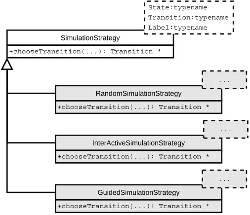
3.2.1 Simulation Strategy . . . 23
3.2.2 Simulation Observer . . . 24
3.2.3 Simulation Algorithm . . . 25
3.3 Generic Search . . . 26
3.3.1 Search Feedback . . . 27
3.3.2 Search Strategies . . . 27
3.3.3 Search Adapter . . . 31
3.4 Transformations of State Spaces . . . 33
3.4.1 Examples of State Space Transformations . . . 33
3.4.2 Enabling Reuse for Transformations . . . 34
4 The Abstract Layer 38
4.1 Design of Software Models . . . 38
4.1.1 Formal Description of the Model-Wide Type Graph . . . 39
4.1.2 Design to Support Typing Information . . . 40
4.1.3 Formal Description of the State Graphs . . . 41
4.1.4 Design of State Representation . . . 44
4.1.5 Formal Description of Transitions and Labels . . . 45
4.1.6 Design of Transition and Label Representation . . . 46
4.2 Transformation to Linearised Representation . . . 48
4.2.1 Linearising Rooted Deterministic Typed Graphs . . . 48
4.2.2 Linearising State Graphs . . . 49
4.2.3 Optimisation of State Linearisation . . . 52
4.2.4 Functionality to Support Bitvector Representation . . . 53
5 Including Features 55 5.1 Change of Generic Layer . . . 55
5.1.1 Symbolic Model Checking . . . 55
5.1.2 Bounded Model Checking . . . 56
5.2 Search Strategies . . . 56
5.2.1 Breadth-First Search Strategy . . . 56
5.2.2 Directed Search Strategy . . . 56
5.3 Specialised Stores . . . 57
5.3.1 State Compression . . . 58
5.3.2 State Caching . . . 58
5.3.3 State Collapsing . . . 58
5.3.4 Minimised Automata . . . 58
5.3.5 Bit-State Hashing and Hash Compaction . . . 58
5.4 Reduction Methods . . . 59
5.4.1 Partial-Order Reduction . . . 59
5.4.2 Symmetry Reduction . . . 60
5.5 Additional Resources . . . 63
5.5.1 Use of External Storage . . . 63
5.5.2 Distributed Verification . . . 63
6 The Tool Layer: Model Checking Prom+ 65 6.1 The Modelling Language Prom+. . . . 65
6.1.1 Syntax . . . 65
6.1.2 Pointer Variables and Dynamic Object Creation . . . 65
6.1.3 Semantics . . . 68
6.1.4 Prom+’s Language Features in Comparison . . . . 70
6.2 The Tool . . . 71
6.2.1 Tool lmplementation . . . 71
6.2.2 Performance . . . 72
7 Conclusion 74 7.1 Summary . . . 74
7.2 Evaluation . . . 76
7.3 Related Work . . . 77
7.4 Future Work . . . 77
A Notation 84
B Dedicated Solution for Depth-First Search 86
C Alternative Abstract Layers 90
D Example Prom+Models 92
List of Figures
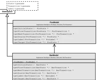
2.1 Models-classes with similarities . . . 14
2.2 Black-box design of model checkers . . . 16
2.3 Layered architecture of the framework . . . 16
3.1 Programmatic interface of a state space . . . 22
3.2 Overview of simulation strategies . . . 24
3.3 Overview of simulation observers . . . 25
3.4 Overview of generic simulation module . . . 26
3.5 Overview ofSearchStrategyandSearchFeedback . . . 29
3.6 Overview ofSearchAdapter . . . 31
3.7 A simple state space tranformation . . . 34
3.8 A tranformation for state compression . . . 35
3.9 A transformation to realise parallel composition . . . 35
3.10 A transformation to supportLTLmodel checking . . . 36
3.11 Reuse of aSimulationObserver . . . 36
4.1 Simplified design of the abstract layer . . . 39
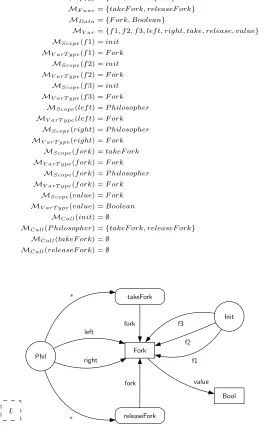
4.2 Type graph of the dining philosophers model . . . 42
4.3 Design of typing information in the abstract layer . . . 43
4.4 State graph of a dining philosophers model . . . 44
4.5 Design of state representation in the abstract layer . . . 45
4.6 Representation of typing functionτσ . . . 45
4.7 Representation of control-flow . . . 46
4.8 Representation of statements and expressions . . . 47
4.9 Transformation ofSoftwareModels toBitvectorModels . . . 48
4.10 Optimisation of state and type graph . . . 52
4.11 Support inTypefor encoding and decodingSoftwareModels. . . 53
5.1 Overview of theBestFirstStrategy . . . 57
5.2 Overview ofStateStores . . . 57
5.3 Inclusion of some specialisedStateStores . . . 59
5.4 Generic implementation of partial-order reduction . . . 60
5.5 A state space tranformation to a quotient system . . . 61
5.6 A symmetric store action . . . 62
5.7 Conceptual setup of a distributed search . . . 63
6.1 The grammar ofPROM+ inEBNFstyle . . . 66
6.2 Representation of pointers in the state graph . . . 67
B.1 Design of a generic depth-first search algorithm . . . 88
C.1 State space defined by a software-based model . . . 90
C.2 State space defined by a graph grammar . . . 90
C.3 State space defined by a Petri net . . . 91
C.4 State space defined by a Rubik’s cube puzzle . . . 91
List of Tables
1.1 Comparison of model specification languages . . . 8
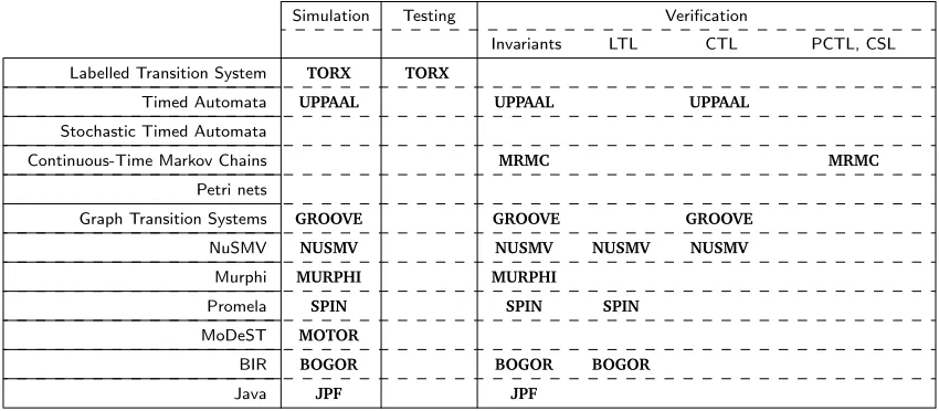
1.2 Overview of tools . . . 8
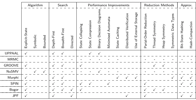
1.3 Comparison of verification tools . . . 12
3.1 Interaction between SEARCHFEEDBACKandSearchStrategy . . . 28
4.1 Linearisation of a state graph . . . 52
4.2 Optimised linearisation of a state graph . . . 53
6.1 Overview of Prom+’s language features . . . . 71
6.2 Comparison of performance . . . 73
List of Algorithms
3.1 T ransitions(s′) . . . 23
3.2 Simulation algorithm . . . 25
3.3 T ryExploreStep(s∈S, r∈R∪ {ǫ}) . . . 28
3.4 T ryBacktrackStep(s∈S, r∈R∪ {ǫ}). . . 29
3.5 Depth-first search strategy . . . 30
3.6 P rovideF eedback(e∈E)−→F . . . 32
4.1 Linearising a graph . . . 49
4.2 Linearising a state graph . . . 51
B.1 Recursive depth-first search algorithm . . . 87
B.2 T ryT ransition(r∈R). . . 88
B.3 Iterative depth-first search algorithm . . . 89
List of Interfaces
3.1 The STATESPACEinterface . . . 21
3.2 The SIMULATIONSTRATEGYinterface . . . 24
3.3 The SIMULATIONOBSERVERinterface . . . 24
3.4 The SEARCHFEEDBACKinterface . . . 27
3.5 The CONDITIONinterface . . . 31
3.6 The ACTIONinterface . . . 31
3.7 The SEARCHSTRATEGYinterface . . . 32
5.1 An incomplete symbolic STATESPACEinterface . . . 55
B.1 The GOALinterface . . . 86
B.2 The STOREinterface . . . 86
B.3 The STACKinterface . . . 87
List of Code Listings
4.1 A dining philosophers model inDSPIN-style. . . 41
6.1 APROM+model of Peterson’s mutex algorithm . . . 67
6.2 Deleting stack variables inC++ . . . 68
6.3 Deleting stack variables inDSPIN . . . 68
6.4 APROM+model illustrating the pointer semantics. . . 69
7.1 A worst-casePROM+ model for thread-symmetry reduction. . . 76
D.1 APROMELAandPROM+model of Peterson’s mutex algorithm . . . 92
D.2 A symmetricalPROM+model of Peterson’s mutex algorithm . . . 93
D.3 APROMELAandPROM+model of Dekker’s mutex algorithm . . . 94
D.4 A symmetricalPROM+model of Dekker’s mutex algorithm . . . 95
D.5 APROMELAandPROM+model of Dijkstra’s mutex algorithm . . . 96
D.6 A symmetricalPROM+model of Dijkstra’s mutex algorithm . . . 97
D.7 APROMELAandPROM+model of two dining philosophers . . . 98
D.8 A symmetricalPROM+model of the dining philosophers . . . 99
Acknowledgements
First and foremost I would like to thank dr. ir. Theo Ruijs and dr. ir. Arend Rensink for their support over the course of this project. Without their constructive comments and the discussions during the weekly meetings I would not have been able to complete this project to the same standard. It is due to an interesting course by dr. ir. Theo Ruijs and prof. dr. ir. Joost-Pieter Katoen that I got interested in formal methods to begin with, for which I would like to thank them.
I would also like to thank my friends and family, and in particular Amy, for their interest in my work, as well as their supportiveness, encouragements and patience.
Chapter 1
Introduction
In the field of software engineering a large part of the development process is spent on testing [45]. Testing helps to identify faults in the implementation of a system, which in turn helps developers to make a system meet its requirements. Because tests typically do not cover all possible system runs, testing does not guarantee the absence of faults [63]. Faults can lead to failures, which are undesirable in any system and intolerable in safety-critical systems such as electronic flight control systems in aircraft or medical systems. For these systems it could be argued that testing alone is not sufficient.
Formal verification, and in particularmodel checking, is a field that complements testing. Rather than ensuring some selective runs of the system behave correctly, the intention of model checking is to formally prove all runs conform to the requirements. Typically model checking is not exercised on the system and requirements directly, but on amodel of the systemandpropertiesrepresenting the requirements. Formal verification can be included in the development process to further reduce the number of faults in a system.
Verifying a model enables the ability to abstract from certain aspects of the system that are irrelevant to the property under consideration. Models can usually be expressed as astate space, which is a transition system that defines the behaviour of the model. A problem that is frequently encountered is the state space explosion[18], which usually refers to the exponential growth of the state space that occurs when a model exists of multiple asynchronous components. The state space explosion makes model checking challenging. A significant amount of research is spent in improving the efficiency of the verification process, developing techniques to reduce the size of the state space and developing other means of enabling the verification of ever more complex models. Verification tools, ormodel checkers, are the key to applying model checking in practice. This thesis discusses the introduction of a framework for model checkers. The rest of this chapter dis-cusses the domain of model checking, and disdis-cusses the objectives of the new framework. Chapter 2 introduces a conceptual design which globally introduces the approach that is used in the frame-work. Furthermore, this chapter relates this design to existing frameworks. Chapter 3 through 5 introduce an implementation of the conceptual design for explicit-state verification. Finally, chap-ter 6 presents a case-study which uses the framework to verifyPROMELA-like models.
1.1
Formal Methods
Model checking is part of the more general field of formal methods, which is concerned languages, techniques, and tools based on mathematical principles [20]. There are a few reoccurring terms in this field:
Introduction – 2
Model A model, often denoted byM, formally describes the behaviour of a system. The model can be derived from an existing system, either automatically or manually, but can also be constructed before any system is created. Verification prior to implementation could be ap-plied to ensure a certain design or protocol is correct before any implementation efforts have been completed. Models of systems tend to abstract from some irrelevant aspects of the sys-tem, for instance by means of abstract interpretation [23, 22]. The termsmodelandsystem are used pretty much interchangeably throughout this report, but one should bear in mind that in reality model checking typically is performed on models of systems rather than the systems themselves. Different means of formally specifying a model are described in section 1.2.2.
Specification The specification formally describes the requirements of the system. In this report the specification is presumed to be in the form ofproperties, which are described in section 1.2.1.
The field of formal methods consists not only of numerous formal languages and techniques, but also offers many tools to put the formal theory into practice. The functionality of tools in the field of formal methods can be categorised into the categories of simulation, formal testing and formal verification.
1.1.1
Simulation
A simulation is a step-by-step execution of amodel. This is not only useful to see whether a model is behaving as expected, but is also useful as a means to provide a trace to an erroneous state. Although simulation is not really a field of research within formal methods, it is a useful function to have in tools that work with models. Simulation is useful for quickly finding simple faults in a model. Faults in the model can reflect faults in the system, or could have been introduced during the modelling phase, meaning the model does not accurately reflect the system.
1.1.2
Formal testing
In the context of this document ‘testing’ should be interpreted as formal conformance testing [63]. Testing assumes the existence of a formal specification and treats a system as a black-box. Selected runs of the system are analysed to see whether the implementation conforms to the specification. The runs are chosen in such a way that if all tests succeed then it is likely that the implementation is correct. Because testing is not exhaustive, testing can’t formally guarantee that the implementation conforms to the specification.
1.1.3
Formal verification
A definition of verification from the ISO/IEC 12207 standard is ‘confirmation by examination and provision of objective evidence that specified requirements have been fulfilled’ [45]. The two main approaches for verification are theorem proving andmodel checking[20]. This thesis focuses on model checking.
Theorem proving ‘Theorem proving is a technique by which both the system and its desired prop-erties are expressed as formulas in some mathematical logic. [..] Theorem proving is the process of finding a proof of a property from the axioms of the system’ [20].
3 – Model Checking Domain
Simulation, testing and verification are complementary. Simulation is a way of quickly finding obvious faults early in the design process. Testing and verification should go hand in hand to ensure the implementation conforms to the specification. Verification only proves that a model of a system conforms to the specification, whereas testing makes it probable that the implementation conforms to the model of the system.
Although our main focus in this document is on a framework to support model checking, the functionality required for simulation and formal testing are closely related to this. For instance, the model representation could be the used for simulation purposes as well as model checking.
1.2
Model Checking Domain
The framework presented in this thesis is intended to support model checking tools (e.g. model checkers). The intention of this section is to provide an overview of the model checking domain. As ideally a framework for model checking would support the model checking domain as a whole. We start with discussion different means of specifying properties in section 1.2.1 followed by a discus-sion of model specification languages in 1.2.2 and 1.2.3. Both properties and model specification languages will be related to tools in section 1.2.4.
1.2.1
Property Specification
In the context of model checking a model either conforms to a property or it does not conform to the property, there is no room for ambiguity. This means the specification of the system has to be presented in terms of some formal language rather than a natural language. There are many formalisms in which one could express properties over a system, the most popular of which are invariants,LTLpropertiesandCTLproperties. These properties all are based onatomic propositions.
Atomic propositions The most elementary part of properties are atomic propositions. For each state of the model these expressions are either true or false. Depending on the type of model such an atomic proposition could be of many different types. Potentially valid atomic propositions are ‘the value of global variabley is equal to1’, ‘processAis blocked’ or ‘value
vis open’.
Invariants Propositional logic can combine atomic propositions and logical operators to form propositional formulae. For each state of the system these formulae hold or don’t hold. These propositional formulae can be used as a means of expressing aninvariantof a model. Invariants are safety properties that hold if for every state of the model the propositional for-mula holds. For instance, say there is an atomic propositiondthat denotes a desirable state of the model, i.e. ‘variablexequals0’. A possible invariant could be denoted by the trivial propositional formula¬d. This informally would be the property ‘variablexnever equals0’. Invariants are considered a very important type of safety properties. A safety property is a property whose violation can be proven by means of a finite trace [1], in contrast to liveness properties. For expressing liveness properties or complex safety properties, temporal logics are required such asLTLandCTL.
Linear Temporal Logic Invariants are not powerful enough to formulate the more complex spec-ifications one would wish to express over a model. This is mainly due to the fact that it cannot distinguish between states of the model. Temporal logics allow us to do just this. Linear temporal logic (LTL) expresses properties over paths. All possible paths of a model consist of a series of states. AnLTLformula is either true or false for each path of the model, and the LTLformula holds for the entire model only if for each possible path of the model theLTLformula holds.
In order to express properties over paths, LTLhas some additional operators compared to propositional logic. Most importantly it has the temporal operators next (X) and until (U). ConsideraandbareLTLformulae andpis a path of the model under consideration. Ifais an atomic proposition then it holds forpif it holds for the first state of p. The formulaXa
Introduction – 4
until operator more terminology needs to be introduced. Consider pathpito be pathpwith
the firstistates removed. The formulaaU bholds forpif there is an∈Nsuch thataholds forp0, . . . , pn−1andbholds forpn.
For convenience one could derive more operators from the given operators, such as eventu-ally (F), globally (G), release (R) and the weak until operator (W). A more concise and more complete reference on the semantics and usage ofLTLproperties can be found in [40]. An example of a validLTLproperty isG(d→ F¬d), which informally means ‘for each state on the path, if variablexequals0then eventually it will not equal0’. This type of property could be used to guarantee the model does not get stuck in a situation wherexis continuously0.
Computation Tree Logic AsLTLproperties are defined over paths, they cannot express properties that discriminate between paths. Computation tree logic (CTL) introduces an existential (E) and an universal (A) operator such that path formulae can be joined to form state formulae. For example, properties such as ‘there does not exist a path such that variablexcan equal 0’ can now be formulated as ¬EFd, which is equivalent toAG¬d. Because all path sub-formulea inCTLare wrapped with a quantifier,CTLproperties express properties over states of a model rather than paths. ACTLformula holds for a model if it holds for all initial states of the model. A more elaborate discussion ofCTLcan be found in [40].
Invariants,LTLandCTLproperties are arguably the most commonly used methods of express-ing properties over systems. But besides these, there are numerous other ways in which one could express the desired behaviour of a system, most of which are adaptations ofLTLandCTL. It is not the goal of this section to provide an exhaustive list of property specifications, but some important alternatives will be discussed briefly.
One aspect which cannot be expressed inLTL nor CTL is probability. An adaptation of CTL
called probabilistic computation tree logic (PCTL) introduces a probability operator over path sub-formulae. An example would beAP>.99(G¬p)which informally states ‘for all paths the probability
that¬palways holds is more than99%’. AlthoughPCTLformulae are syntactically very similar to
CTL, the verification algorithms that are to used are significantly different. Also it should be taken into account that in order for a PCTLformula to be meaningful a model would need to have a notion of probabilities.
All previously defined property specifications cannot handle time requirements very well. The only means of addressing time in LTL,CTL orPCTLis by means of saying one event occurs after another. It is not quite difficult to express properties like ‘doccurs within5time units’. Continuous stochastic logic (CSL) combines the probabilistic features of PCTLwith an additionaltimed-until operator. An example of a property specified in CSLis AP>.99(⊤U<5d)which informally states
‘for all paths the probability thatdholds within5time units is at least99%’.
A more extensive explanation of bothPCTLandCSLcan be found in [50]. Again, it should be noted that there exist many other variations of property specifications.
1.2.2
Model Specification
Similar to properties, system models can be specified in numerous different ways. In theory any means of formally specifying a model could be used for the purpose of model checking. In prac-tice there are some model specifications that are used quite often. In this section some of these formalisms will be described.
Labelled Transition System A labelled transitions system (LTS) is arguably the most elementary way of describing a system. A system is defined by means of a set of states (S), a set of labels (L) and a transition relation (R⊆S×L×S). Although usually not included in the definition ofLTS, one could argue that you also need an initial state (I ∈ S), and in order to check the properties described in section 1.2.1 one would need to be able to evaluate whether an atomic proposition holds in a state. Similar toLTSare finite-state automata such asDFAand
NFA, but also B¨uchi automata and Kripke structures.
5 – Model Checking Domain
(R ⊆ S×L× B(C)× P(C)×S) where B(C)is a set of clock constraints that guard the transitions. Clock constraints are simple expressions on clocks such as ‘clockchas a value smaller than 5 time units’ (c < 5). Transitions of aTA are labelled with these constraints.
P(C)is the powerset of clocks, such that each transition is labelled with a set of clocks that is to be reset. Additionally one can label states with invariants (Y : S −→ B(C)). Clocks in timed automata have rational values which increase as time progresses. More detailed information onTAin the context of model checking can be found in [2, 68, 9].
Stochastic Timed Automata Stochastic timed automata (STA) are fairly similar to timed automata in the sense that they have clock variables. However, clocks inSTAdo not increase in value as time progresses, but they are triggers that count down. A STA consists of triggers (C), states (S), labels (L) and a transition function (R ⊆ S×L× P(C)×S), where P(C)is the trigger set (the set of triggers that need to be expired for the transition to be enabled). An STA also has a clock setting function (Set : S −→ P(C)) and a distribution function (F : C −→ (R −→ [0,1])). When the STA is in state s, all triggersc ∈ Set(s)are given a value according to their distribution function F(c). This means that STA models are both timed and probabilisitic. More information onSTAcan be found in [25, 24].
Continuous-Time Markov Chains Continuous-time Markov chains (CTMC) consist of a set of states (S), a set of labels (L) and a transition function (R ⊆ S ×S → [0,∞)). The la-bels no longer are associated with transitions, but they are associated with the states by means of some labelling function (L′:S−→L). Transisitions inRare paired with a
param-eterλ∈[0,∞)which is the parameter in a memoryless distribution functionF(x) =λe−λx.
The chance that the transition s → s′ occurs within t time units is equal to Rt
0F(x)dx =
1−e−R(s,s′
)t. More information onCTMCs can be found in [3]. There also exists a
discrete-time Markov chain variant, DTMC, which directly associates each transitions with a proba-bility rather than a distribution function.
Petri nets In a Petri net the transitions are defined different to the models presented so far. A petri net has states (S), transitions (T) and a transition function (R: (S×T)∪(T×S)→N). At any one time all states inShave a particular number of tokens associated with them. These tokens make up the marking of the Petri net. If a transition fromT is fired, thenRhelps to redistribute these tokens. For instance ifR(s1, t1) = 1then ift1is fired, the number of tokens
ins1 is decreased by one. Similarly, ifR(t1, s2) = 2andt1 is fired, the number of tokens in s2is increased by two. The initial marking of a Petri net is given by a functionI:S −→N. A
more detailed discussion on the semantics of Petri nets can be found in [53, 34].
Graph Transition Systems In graph transformation systems (GTS) states (S) are graphs. The transitions relation (R) consists of injective graph morphisms on graphs inS. Graph gram-mers can be used to specify the transitions of aGTSin terms of graphs as well. The interested reader is referred to [57] for more information.
The formalisms that have been presented so far are all mathematical models. This is an ad-vantage in the sense that the semantics of these type of models are well-defined. However, as the systems that are modelled grow increasingly complex a more scalable approach can prove prof-itable. The formalisms that will be presented from here on will be based on textual representations rather than mathematical models, and are comparable to programming languages,. This offers the advantage that abstract concepts such as processes, locks, classes and functions are easily included in a model, but has the disadvantage that the exact semantics of these models is much harder to define and comprehend. It is not uncommon for the semantics of these textual representations to be interpretable as one of the previously defined mathematical formalisms. For instance one could say that thesemantic modelofMODEST-models are stochastic timed automata [24].
In this section only a very general description of these model specification languages will be given, but a comparison will follow in the next section (1.2.3).
Introduction – 6
Murphi The specification languageMURPHIis based on guarded rules. At any one time a rule may
execute if its guard is enabled. There are no such things as processes, functions, or other high-level features.MURPHIis mostly used for protocol verification. An interesting feature of
MURPHIis the support of scalar sets, which enables symmetry reductions during verification
(see also [61, 62]).
Promela Process meta languagePROMELAis the input language of model checkerSPIN[36]. Due to the popularity of this tool, PROMELA is a prominent language in the world of software
and protocol verification. As the name suggests a PROMELA-model is defined as a set of
asynchronous processes. The exact semantics ofPROMELAare dictated by the implementation
ofSPIN, although formal semantics have been derived in [67].
MoDeST The semantic model ofMODEST-models is based on stochastic timed automata, therefore
MODEST-models are probabilistic and timed. The main objective ofMODESTis to be able to express many types of submodels [24], such as timed automata and CTMCs. Due to the complex nature of this language and its semantic model, building a verification tool for
MODESTcould prove difficult.
BIR Bandera intermediate language (BIR) is the input language of the model checkerBOGOR.BIR
has a lot of high-level constructs in order to model object-oriented software. In particular it is well suited for modellingJAVAprograms. The languageBIRitself is extensible, its syntax can be extended inBIR itself and the semantics can be implemented in JAVA. The formal
semantics ofBIRhave not been described in literature, and are presumably fairly complex. See also [27, 60, 59].
Java ObviouslyJAVAis a programming language, but in the current context it is suggested that
JAVA-programs are also models. The JPF-tool is capable of verifying and simulating JAVA
models, and the java virtual machine (JVM) could also be seen as a tool for simulating (e.g. executing) JAVA-models. Not all JAVA-programs are closed systems, as they might require
some interaction with the user. In order to exhaustively verify aJAVA-program it needs to be
closed.
1.2.3
Comparison of High-Level Model Specification Languages
The high-level model specification languages described in section 1.2.2 have only been discussed briefly. To get more insight into the class of models that can be expressed in these languages, a selection of model features is presented. Which features are present in which model specification language is depicted in table 1.3.
Control-Flow A first category of model features concerns different ways of defining the control-flow in sequential systems. Some basic control-control-flow constructs such as conditional statements and loops are not considered features, as they are very common. A less common feature is is the ability tojumpto arbitrary locations in the control-flow, similar to the old-fashiongoto
statement inBASIC. Although jumps are not considered very modular from a programming perspective, in modelling languages they can simplify modelling systems with complicated control-flows. Functionsare a way to easily model a complicated or repetitive control-flow by composing it of smaller control-flow units. An execution unit, called a thread or pro-cess, has a stack of functions associated with it in order to keep track of the control-flow. Exception handlingis a way of abruptly changing the flow of control in case of exceptional circumstances. If such an exceptional circumstance occurs, an exception is thrown down the function stack until there is a function that knows how to handle such a exception. This function willcatchthe exception. Finally, it is considered a feature if a model specification language explicitly allows the composition of a model from multipleparallel threads. Note that such threads could execute either synchronically or asynchronically.
Communication As most models allow compositions from parallel components1, this category
1These components are mostly threads or processes, but in the case ofMURPHIthey areguarded rules, and inNUSMV
7 – Model Checking Domain
of model-features concerns the communications and synchronisation between those compo-nents. Anatomicconstruct enforces that a single component is the only component to be active while its control-flow is within such an atomic construct. Atomic statements are useful when modelling systems where mutual exclusion is required, and can significantly reduce de size of the state space to be verified. Locksin effect accomplish the same, but in a different way. Where atomic constructs are explicitly part of a specification language, locks are objects which grant access to certain resources. Only one component at a time can gain the lock, through which mutual exclusion is achieved. A method of communications between compo-nents is viachannels, where messages are interchanged amongst components. If the case of a non-buffered rendez-vous channel the components need to synchronise in order to exchange messages.
Data Abstraction The following category of features concerns data abstraction. It is presumed that all major model specification languages support primitives data types and variables, such as integers and booleans. More interesting arecomposite typessuch as records. These composite types can be composed from a number of other types. Although this is not nec-essarily very useful by itself, it does make it possible to bundle information that intuitively belongs to the same entity.Classesare similar to composite types, but also include functions. A model specification language will be shown as capable of inheritance if it is possible to define inheritance relations between data types. A subtype inherits all the fields of all its parent-type. Inheritance can also be defined over classes. Functions of a super-class can be overloaded by sub-classes. A language can model method overridingif a model can dy-namically resolve the function to execute during run-time, depending on which sub-class the function call was made. Another feature to consider is the ability to definecustom data types. With this term we do not mean the composite types or classes mentioned previously, but new data types that can be included as if they were supported by the modelling language natively. Finally, a special mention is given tosymmetric data types. These are sets for which the or-der of the elements is not interesting, as only symmetry preserving operations are allowed. Scalar sets can be a useful way of defining symmetries in the data of models [43, 42].
Furthermore, it is considered a feature if the model specification language supports the dynamic creation and deletion ofobjectsorthreads. If threads cannot be created dynamically, then every single state of the model consists of the same number of threads, which might not be flexible enough to model some systems. Dynamic object creation is useful for modelling heap-like memory models of programs.
Other features are the inclusion of assertions in the model specification. These are in fact part of the property specification rather than the model specification. An assertion is basically an expression that should hold in a certain set of states of the model, dictated by the location at which it is defined in the model. Also, some specification languages have means of modellingclocks, or probabilities. Table 1.1 shows which features can be found in the modelling languages presented in the previous section.
1.2.4
Overview of Tools
So far the tools belonging to the model checking domain have been mentioned only sporadically. In table 1.2 an overview of tools is given in relation to the property specification and model spec-ification languages presented in previous sections. In this section these tools will be addressed only briefly, whereas in the next section a comparison of these tools will be presented. Again, the selection of the tools that are presented here is not exhaustive and is slightly biased towards explicit-state verification, but it should give the reader some idea of the capabilities of the tools in this field. The scope of this document does not allow a very extensive discussion on the features and techniques in the field of model checking. Besides the brief discussion of the features some relevant literature will be provided. Furthermore, chapter 5 explains how these features see fit in the framework, which might provide some additional insight into the features discussed in this section.
Introduction – 8
Table 1.1– A comparison of model specification languages based on se-lected language features.
Control Flow Comm. Data Abstraction Miscellaneous
S em a n ti c M o d el J u m p s F u n ct io n S ta ck s E xc ep ti o n H a n d li n g P ar a ll el T h re a d s A to m ic Lo ck s Ch a n n el s Co m p o si te T yp es Cl a ss es In h er it a n ce o f D a ta M et h o d O ve rr id in g Cu st o m D a ta T yp es S ym m et ri c D a ta T yp es D yn a m ic D a ta Cr ea ti o n D yn a m ic T h re a d Cr ea ti o n A ss er ti o n s Cl o ck s Pr o b a b il it ie s
NuSMV LTS X X X
Murphi LTS X X X X
Promela LTS X X X X X X X
MoDeST STA X X X X X X X X
BIR LTS X X X X X X X X X X 2 X X X
Java LTS X X X X X X X X X X X X
Table 1.2 – A selection of tools put into the context of the previously presented property specifications and model specification languages.
Simulation Testing Verification
Invariants LTL CTL PCTL, CSL
Labelled Transition System TORX TORX
Timed Automata UPPAAL UPPAAL UPPAAL
Stochastic Timed Automata
Continuous-Time Markov Chains MRMC MRMC
Petri nets
Graph Transition Systems GROOVE GROOVE GROOVE
NuSMV NUSMV NUSMV NUSMV NUSMV
Murphi MURPHI MURPHI
Promela SPIN SPIN SPIN
MoDeST MOTOR
BIR BOGOR BOGOR BOGOR
Java JPF JPF
TorX TheTORXtool is a tool for simulating and testing labelled transition systems. The nature of a test tool is to check a chosen set of runs of a system to see whether they conform the the specifcation. TORXallows models to be specified inLOTOS,SDLandPROMELA[64].
UPPAAL UPPAALis a tool for the simulation and verification of timed automata (TA). Timed au-tomata are directly drawn in a graphical user interface. UPPAAL is capable of verifing CTL
properties. The verification algorithm first translates aTAinto a zone-automaton (i.e. anLTS -like representation in which each state is a zone is which the clock values are similar; see [9]). An interesting feature ofUPPAALis the possibility of verifying models in a distributed fashion [7].
9 – Model Checking Domain
ofPCTLas well as CSL. Verification algorithms used inMRMC are significantly different to those used for non-probabilistic models [3].
GROOVE GROOVE is a tool for the exploration of GTS models as defined by graph grammars [58, 57]. Graph grammars allow a representation of states and transition rules in the form of graphs. This arguably is a more natural way of representing systems. Recently,GROOVE
was extended with the capability ofCTLmodel checking [47].
NuSMV The model checkerNUSMV is different to other tools presented here in the sense that it is oriented toward verifying models based on hardware. It uses a symbolic verification algo-rithm for the verification of mainlyCTLproperties. It is possible to specify some properties inLTL, which are translated to equivalentCTLproperties by the tool.
Murphi MURPHI is a tool for the verification of models specified in the MURPHI language. As
this language is based on guarded rules, it is not very suitable for modelling object-oriented systems, but it is well suited for the verification of protocols. As mentioned in section 1.2.2 an important feature of MURPHI is the support of symmetry reductions by means of scalar
sets [43, 42]. The tool supports distributed verification as well as use of a magnetic disk (to increase the size of models that can be checked) [62, 61].
SPIN TheSPINmodel checker is arguably the most popular tool in the field of formal verification. It a tool for verifyingPROMELAmodels againstLTLproperties, and is efficient in doing so. It applies specialistic techniques such as partial-order reductions, bit-state hashing and hash-compaction in order to improve performance, and therefore the size of the models that can be verified withSPIN[36]. Also, it is capable of enforcing weak fairness and checking progress requirements. As can be seen in table 1.3SPINsupports a lot of optimisation features. The source-code ofSPIN is optimised for performance. The downside of this is that the tool is not written in a modular fashion. Reusing and extendingSPINis therefore difficult.
MoToR The toolMOTORis currently only a simulator forMODEST-models. As part of theHAAST
project it is the first step towards verification of these complex models.
Bogor BOGOR is a model checker for models specified in BIR. It is an example of a tool that is written in a modular and extensible way. Modules can be written to be used in BOGOR,
but also theBIRlanguage can be extended. The correlation betweenBIRand JAVAis very
high, making BOGOR an interesting choice for the verification of object-oriented programs.
There exist modules for BOGOR that perform symmetry reductions as well as partial-order
reductions.
JPF JAVAPATHFINDER(JPF) is a verification tool forJAVAprograms. It is useful for finding deadlocks
inJAVAprograms. It is also possible to define custom properties inJAVAitself. The first version
ofJPFtranslatedJAVAprograms intoPROMELAmodels, so that they could be verified bySPIN. The current version is built like a virtual machine which explores every possible path of execution. It applies partial-order reduction, state collapsing and hash compaction in order to improve efficiency [36].
1.2.5
Comparison of Verification Tools
Comparing all tools mentioned in section is rather difficult, as they were all built for different purposes. Therefore this section will limit the comparison to the comparison of model checkers. The intention of this section is to provide a list of features that can occur in model checking tools, and should therefore be compatible with the framework. Chapter 5 will discuss how these features can be included in the framework. The comparison is based on the features presented below:
Introduction – 10
Insymbolicverification algorithms states are not individually represented. The algorithm is based on operations onsetsof states. These sets can be symbolically represented by means ofBDDs. This approach is useful for model checkingCTLproperties [16]. Finally, there is a distinguishable category calledboundedmodel checking. This technique first transforms the state space into a formula in propositional logic. This formula is constructed in such a way that it is only satisfiable if some states of interest are reachable, after which a satisfiability solver determines whether there exists a solution [17]. It is called bounded model checking because only paths upto a particular number of transitions are considered.
Henceforth, our comparison criteria will be biased towards explicit-state verification algorithms.
Search Strategies If a tool uses anexplicit-stateverification algorithm, there is usually a choice as to the order in which states in the state space are visited. The most common choice is to use adepth-firsttraversal strategy. If a violation is found during depth-first traversal, the path to the current state is given by the search stack, which can be used as a path to the erroneous state (e.g. counter-example).
Another possibility is abreadth-firsttraversal strategy. The advantage of a breadth-first explo-ration is that when a property violation is found, it is guaranteed that the counter-example of this violation is the shortest counter-example possible. However, unlike a depth-first traver-sal, you do not get this counter-example for free, as there is no longer a search stack to extract the counter-example from. Another disadvantage is that a breadth-first approach is usually more memory intensive.
Finally, the category ofdirectedstrategies is distinguished. The search algorithms in this cat-egory use some heuristic to determine the order of traversal, in the hope of finding property violations sooner. Popular directed search methods arebest-firstandA* [29, 28, 52]. Most other features in explicit-state verification are a direct result of thestate space explosion [18]. Tools strife to verify continuously large models. The ways in which they realise this can be categorised intoperformance improvements,reduction methodsandapproximative methods.
Performance improvements The capabilities of tools, in both time and memory, is continuously improved upon, which enables the verification of models with increasingly large state spaces. Performance can be improved by means of more efficient algorithms and more efficient stor-age techniques, but also by finding alternative resources.
State collapsinguses the fact that models are made of of components [35]. Rather than stor-ing each individual state separately, states could share information about the components. If in two global states have a process component in common, which is coincidentally also in the same state, it is sufficient to store this information only once.
State compressionattempts to reduce the size of the bitvectors that represent states [35]. A Huffman encoding could be used for this purpose. Some training runs might be necessary to analyse the frequency of bytes in order to optimise the compression.
Rather than storing every single state that was once visited, one could employ a caching strategy [33]. The larger the cache, the less likely it is that states are revisited. The cache could store as many states as the memory allows. The risk of caching is that states could be visited more than necessary because they have been deleted from the cache.
If states are represented by vectors of bits, it is possible to use a minimised automaton to serve the function of a state store [37, 36]. This automaton is labelled with bit values, and accepts only the bitvectors that represent the states that have been visited.
A technique that is used in the context of symbolic verification algorithms is that of binary decision trees BDD [13]. Such a decision tree is capable of storing binary function in a memory-efficient way. As each state is distinguishable by the set of atomic propositions it satisfies, we could interpret the set of atomic propositions as a set of boolean variables. The
BDDcan very efficiently represent a set of states.
11 – Model Checking Domain
of models that can be verified, it is hard to devise algorithms that allow the verification to be distributed [51, 61, 6].
Besides using memory for storing the visited states, it is also possible to useexternal storage such as a hard drive. Although the capacity of hard drives is greater than memory, access to the drive is relatively slow. This means using the magnetic disk for verification comes at a performance hit. Special algorithms can be devised to use the disk without too many drawbacks [62].
Reduction methods An active field of research is developing methods to significantly reduce the size of a model’s state space, whilst ensuring the verification result remains formally correct. First of allpartial-order reductionis a commonly applied technique to reduce the size of the state space. This reduction is based on the commutativeness of transitions. For instance if there are two threads that are about to perform a transition, and those two transitions are do not affect each other, there might be a situation where a reduction can be applied. Rather than verifying all possible orders in which the transitions could execute, it might be sufficient to explore only some orders of execution. This technique is quite complex and dependent on the type of model at hand, therefore the interested reader is referred to chapter 10 of [19] or [32, 55] for more specific information. The inclusion of partial-order reduction in the framework is discussed in section 5.4.1.
Another reduction method is that ofsymmetry reduction[52, 10]. Symmetries within a model are used to reduce the state space of models considerably. If two states are symmetrical, and the property does not distinguish between those states, it is sufficient to explore only one of those states. There are numerous of possible symmetries that can occur within models, depending on the type of model at hand. However, in the context of software-based models one could distinguishthread-symmetry,heap-symmetryandsymmetric data types.
First we considerthread-symmetry[60]. Consider a dining philosophers system where each philosopher is modelled by a process. One could argue that it doesn’t matter which philoso-pher takes the first step, because if any other philosophiloso-pher would have made this step the result would be is symmetrical. Two states are equal except for a permutation of processes instances.
Another symmetry that could occur is heap-symmetry, which focusses on permutations of heap objects rather than threads [60]. The idea of heap symmetry is that it is usually irrele-vant what the identity of an object is, or where it is located in memory, as long as the heap structure is the same.
Finally one could also introduce special data types to help to identify symmetry, such as scalar sets [42]. For instance one could have a scalar set of process identifiers. On such a set one can only perform operations that preserve symmetry. It is useful if one would like to iterate over processes and the order of iteration is not relevant. We will refer to these assymmetric data types.
Approximative methods Some techniques abandon the principle of formal correctness for an ap-proximate result. This allows the verification of model checking much larger models. Bit-state hashing and hash-compaction are commonly applied approximative methods [48]. Bit-state hashing or supertrace is such an approximative method. A very large bitvector of is created, and with a hash function each state is mapped to a bit in this vector. A search algorithm uses this vector to see whether it already visited a state instead of a store. This means that there is a small chance that an erroneous state will not be found, because two states can map to the same bit in the bit vector. This means it is possible for the search to wrongly conclude it has visited a state, thereby omitting a portion of the state space in which erroneous states could still reside [48, 36].
Introduction – 12
Table 1.3– A comparison of verification tools. Note that most features of comparison are chosen to compare explicit-state verification, rendering the inclusion ofNUSMV and MRMCrather useless. Features that aren’t applicable for a tool are marked by a ‘-’.
Algorithm Search Performance Improvements Reduction Methods Approx.
E xp li ci t-S ta te S ym b o li c B o u n d ed D ep th -F ir st B re a d th -F ir st D ir ec te d S ta te Co ll a p si n g S ta te Co m p re ss io n B in ar y D ec is io n D ia g ra m s M in im is ed A u to m a ta S ta te Ca ch in g D is tr ib u te d V er ifi ca ti o n Us e o f E xt er n a l S to ra g e P ar ia l-O rd er R ed u ct io n T h re a d S ym m et ry H ea p S ym m et ry S ym m et ri c D a ta T yp es B it -S ta te H a sh in g H a sh -Co m p a ct io n
UPPAAL X X X X X
MRMC - - - - - - - - - - - - -
-GROOVE X X X X X X
NuSMV X X - - - - - X - - - - - - -
-Murphi X X X X X X X X X
SPIN X X X X X X X X X
Bogor X X X X X X X X
JPF X X X X X X X
1.3
Problem Statement
As is illustrated by table 1.2 most tools are very specialised, meaning they have been developed with the goal of supporting only a single model specification language and only a small number of different property specifications.
This specialisation enables the code-base of a tool to be optimised for a particular purpose and does not encourage a modularandgenericdesign. As a result, it is usually quite fruitless to attempt to reuse the source code of these tools, and new tools are often written from scratch. Any opportunity to share the functionality of tools is not exploited. Because tools do not share a common code-base the interoperability of tools is quite poor. Interaction between tools can only be achieved with considerable effort.
To address these issues this thesis introduces aframeworkfor model checkers, where the meaning of framework is two-fold:
Conceptual architecture A conceptual design of model checking tools which enables the reuse of code and encourages a modular design. This conceptual design is applicable in a wider perspective than just explicit-state model checking. It provides an architecture in which algo-rithms can be reused for different kinds of models. The conceptual architecture is discussed in chapter 2.
The library A library which has been designed using the principles of the conceptual architecture. On a high level of abstraction this library defines means of simulating and verifying explicit-state models (chapter 3). On a low level of abstraction it provides an implementation of
PROMELA-like models (chapters 4, 5 and 6).
Both will be referred to as ‘framework’ in the remainder of this thesis. The introduction of a framework should help towards improving the previously described scenario in the model checking domain. More specificly, this thesis works towards the following objectives:
13 – Problem Statement
functionality which can be used for a number of different models. By providing reusable functionality and algorithms in a framework, new tools would no longer have to be build from scratch. The development of new tools would be easier and the resulting code more modular.
Chapter 2
Conceptual Architecture
The previous sections are intended to justify the development of a new framework in the model checking field. In particular section 1.2.4 shows that most tools are very specialised and integration of tools in this field is difficult. Rather than introducing a new black-box framework, which takes input in the form of some complex and expressive intermediate language, this framework should be more open, as is explained in the next few sections.
2.1
Unification of the Model Checking Domain
The main challenge when designing a model checking framework is to find a way to combine all the modelling languages, property specifications and verification algorithms in one single framework in a way such that reuse of code and modular design are possible.
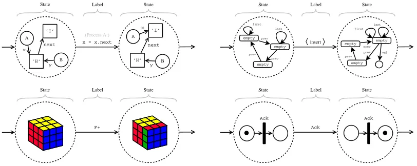
Unfortunately, it is not necessarily the case that all system models share a common represen-tation at a high level of abstraction. For instance probabilistic models have a different state space representation to non-probabilistic models. However, it is possible to identify models types that share an identical representation on a high-level of abstraction, such as those depicted in figure 2.1. When we abstract from the internal structure of states we can describe models of this type as a labelled transition system.
x = x.next
A
B x
y ’H’
’I’
next
A
B
x
y ’H’
’I’
next
State Label State
(Process A:)
State Label State
empty empty
empty prev
prev prev
first last
empty empty
empty prev prev
first last
prev val insert
State Label State
F+
State Label State
Ack
Ack Ack
Figure 2.1– These model types are identical on a high level of abstrac-tion. However, on a lower level the internal structure of states, transitions and labels are totally different. These figures are shown in more detail in appendix C.
15 – Unification of the Model Checking Domain
opportunity to provide reusable functionality, in terms ofgeneric algorithms, which can be used for multiple model types.
We identify two main approaches that can be used to create a new framework, namely the black-box approachand thelayered approach.
2.1.1
The Black-Box Approach
In general model checkers have one formalism in which the system model has to be defined (e.g.
BOGORrequires models to be specified inBIR). One could continue this philosophy when designing a framework. Preferably, one would choose a semantically rich modelling language, such that a number of other model types can be expressed in this language. For example, if one chooses
MODESTas the input language for a framework, the framework would also supportCTMC-models andTA-models, as these can be expressed inMODEST.
Whether there exists one particular modelling language in which all other models can be ex-pressed is questionable. Therefore a framework using this approach would probably only support a limited part of the model checking domain. There are a few reasons why one could argue defining a common input formalism is not a suitable approach for a model checking framework:
• By choosing one particular input formalism the framework is limited to a certain class of system models that can be expressed in this formalism. Additionally, even if it is possible to express a model in this formalism this does not necessarily mean this is the optimal way to verify such a model.
• By limiting the framework to a particular input formalism one would also limit the frame-work to frame-work on a particular level of abstraction. Although it might be possible to express models of a different level of abstraction in the given formalism, this conversion might not be optimal.
• Consider the chosen formalism is quite complex, which is a valid assumption given the fact that the intention is able to express many different types of models in this formalism. Ar-guably, devising a verification algorithm for such a complex language is difficult.
However, besides these disadvantages, this approach also has some some advantages:
• The required functionality to provide a framework would be straight-forward. By providing simulation, testing and verification functionality for the chosen formalism, the framework would be complete.
• Because the framework would only work with a single formalism the verification procedures can be optimised for this single formalism.
In figure 2.2 the black-box principle is illustrated by means of the model checkersSPIN, MURPHI
andBOGOR. The figure shows that different model checkers require different input formalisms.
Note that we omitted the input of property specifications. Converting one formalism to the other is at the least inefficient and undesirable, at the worst this is impossible. Model checkers are designed in this way is because they don’t need to be reusable or generic, and optimisation of the tool is easier on a single well-defined input formalism. In principle one could call any model checkers a model checking framework in terms of the black-box approach, which isBOGOR’s approach [59].
However,BOGORdoes allow a custom implementation of some modules and alterations of its input
language (see section 2.2.1).
2.1.2
The Layered Approach
Rather than employing a black-box approach, a framework could employ a more open approach. For instance, the framework could supportPROMELA-like models, but at the same time allow other
Conceptual Architecture – 16
SPIN Murphi Bogor
BIR
Promela Murphi
?
?
?
Figure 2.2– In general model checkers can be considered black-box sys-tems with models as input, specified in some particular formalism, and a verification result as output. In this figure the black-box nature ofSPIN,
MURPHIandBOGORis illustrated.
algorithms where possible. Note that the models provided in figure 2.1 is not the only group of models for which one could denote similarities.
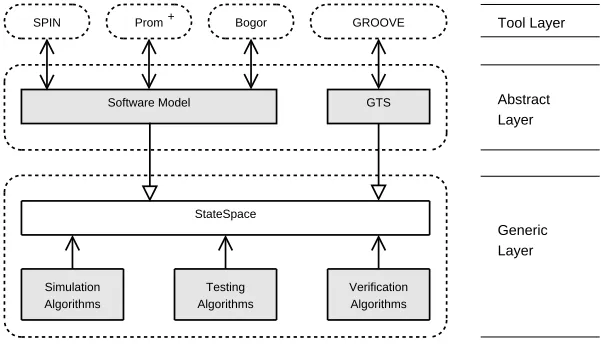
Figure 2.3 introduces a layered architecture. The bottom layer represents the model on a high level of abstraction, whereas the top layers are more concrete. Reuse can be accomplished by sharing layers with a high abstraction. We can distinguish three layers, the generic layer, the abstract layer and the tool layer. As is intuitively clear, the generic layer and abstract layer are provided by the framework, and the tool layer is meant for tools that use the framework.
Generic Layer Abstract Layer Tool Layer
SPIN GROOVE
Software Model
StateSpace
GTS
Simulation Algorithms
Verification Algorithms Bogor
Testing Algorithms Prom+
Figure 2.3 – The proposed framework can be divided into three main levels of abstraction: thegeneric layer, theabstract layerand thetool layer.
Generic layer The generic layer provides algorithms for certain types of models. For instance, one could provide simulation, testing and verification algorithms for the class of models depicted in figure 2.1.
It is not feasible to define just one generic layer for all models, this is due to the diversity of models in the model checking domain. For instance, the fields ofexplicit-state,symbolic, boundedand probabilistic model checking are too different to be encapsulated within the same generic layer, and should probably be defined in separate generic layers.
17 – Related Work
Abstract layer The abstract layer is the layer on top of the generic layer. In particular it gives an internal structure to the generic layer. For example, in figure 2.1 where the generic layer was only concerned with models on the level of states, labels and transition, the abstract layer provides the internal structure to these concepts, such as Rubik’s cubes or Petri nets for states.
The idea is that it is possible to have multiple abstract layers on the same generic layer such that the algorithms of generic layers are reused.
Tool layer The tool layer is not provided by the framework, it is included in the figure to show how tools could use the framework. In chapter 6 there is small case study of a tool forPROMELA
-like models, in which the intention of the tool layer should become clear. The nature of the tool layer is that it is not reusable, however, the idea is that a well-defined abstract layer could be used by multiple tools.
The layered approach has a few advantages compared to the black-box approach:
• The framework would not be limited to one input formalism, nor would it be necessary to convert between input formalism.
• Usage of the framework is not limited to a single level of abstraction. As the architecture consists of layers, it is possible to use the functionality provided in the framework at several levels of abstraction.
Besides these advantages, the layered approach also has some disadvantages:
• The required functionality of the framework is not straight-forward. It would be difficult to know which generic and abstract layers are required in order to truly call the framework a model checking framework.
We argue thelayered approachsuits our goals much better than theblack-boxapproach. It en-ables the reuse of algorithms, and it also enforces a modular design due to the modularisation in layers. Note that this chapter only presents aconceptual architectureof the model checking frame-work. The rest of this thesis concerns a possible implementation of this conceptual architecture.
To be more specific, thegeneric layer presented in chapter 3 is based on explicit-state model checking. It provides functionality to support the simulation as well as verification of ‘explicit-state models’, no testing algorithms are taken into consideration. Theabstract layeruses a graph-based representation of states to model software-based models in chapter 4. Finally, thetool layer uses the generic and abstract layer to verify aPROMELA-based specification language calledPROM+ in
chapter 6.
2.2
Related Work
Although chapter 1 explained why a framework for model checking is desirable, there has not been a discussion of other frameworks in this field of research. In this section these frameworks will be introduced. A brief overview of the features of these frameworks will be given, alongside with an explanation how their approach relates to our conceptual design.
2.2.1
Bogor
Besides being a model checker forBIR,BOGORis often portrayed as a model-checking framework
[59, 27]. This framework chooses BIRas the language in which all models are to be specified. AlthoughBOGORcould be described as a black-box framework (see section 2.1.1), it does have a
few features that provide some additional flexibility:
• BIR is an extensible language. It is possible to introduce new language features to extend
Conceptual Architecture – 18
• The model checker BOGOR is written in a modular fashion. It defines several interfaces
for which custom modules can be implemented. Examples of such interfaces are the
IStateManagerand theISchedulingStrategist.
This approach has several disadvantages, which convince us this architecture is not ideal for a model checking framework. Firstly, the black-box nature of BOGOR is our main concern. As
all input is given in terms of BIR, we argue thatBOGOR is only a suitable framework for models
that are semantically similar to BIR. As the BIR specification is fairly similar to object-oriented programming languages such as JAVA, it could be argued thatBOGORis only suitable for this type
of models.
The second issue concerns the flexibility provided by the interfaces. These are custom modules that can be used to implement features. A problem arises if multiple features require the custom implementation of the same module. For instance, in order to implement both symmetry reduc-tions and state collapsing, the state store module, orIStoreManager, requires a custom implemen-tation. With two independent features there are 4 possible configurations in which the verification can be executed. It is undesirable to implement a custom implementation of the module for each configuration.
2.2.2
Concurrency Workbench
In article [21] a framework for verifying concurrent systems is described. It is a combination of a toolkit called the concurrency workbench (CWB-NC) and a process algebra compiler (PAC-NC). In this section this framework will simply be referred to as ‘the concurreny workbench’. This framework assumes a language has well-defined semantics in the form of structured operational semantics (SOS). These rules could be compared to inference rules which describe a transitions of the system [21]. The process algebra compiler is used to generate a parser from a set ofSOS-rules. This parser can parse a model specification and generate aLTSthat describes the semantics of the model. The concurrency workbench toolkit is used to verify theLTS.
In effect this framework is language-independent, which could be considered a feature as well as a shortcoming. The advantage is that if the semantics of some model specification language are available inSOS, then by giving the framework these rules we should in theory be able to verify this type of models. This would involve minimal effort, and provides a great deal of flexibility.
The disadvantage is that not all languages have formally defined semantics. For a specification language likePROMELA, it is very difficult to constructSOS-rules [67]. We argue it is fair to say that providing these rules is not always trivial.
2.2.3
Model Checking Kit
The Model-Checking Kit of the University of Stuttgart uses a layered approach [54]. This is similar to the approach described in section 2.1.2, in the sense that specification languages are mapped to a generic layer by means of abstraction. The verif
![Figure 3.4 – An overview of the generic simulation module, whichcombines the functionality of [[StateSpace]], [[SimulationStrategy]] and[[SimulationObserver]].](https://thumb-us.123doks.com/thumbv2/123dok_us/1164149.1146556/37.595.153.491.82.291/figure-overview-simulation-whichcombines-functionality-statespace-simulationstrategy-simulationobserver.webp)