CSEIT184625 | Published – 08 May 2018 | May-June 2018 [ (4 ) 6 : 116-122 ]
National Conference on Engineering Innovations and Solutions (NCEIS – 2018)
International Journal of Scientific Research in Computer Science, Engineering and Information Technology
© 2018 IJSRCSEIT | Volume 4 | Issue 6 | ISSN : 2456-3307
116
Implementing Intelligent Traffic Control System for
Congestion Control, Ambulance Clearance, and Stolen
Vehicle Detection
Gul Afshan, KavyaShree D, Nischitha H.D, Swetha Rani S, Prof. Prashanth M. V
Department of Information Science & Engineering Vidyavardhaka College of Engineering Mysuru, Karnataka, India
ABSTRACT
This paper presents an intelligent traffic control system to pass emergency vehicles smoothly. Each individual vehicle is equipped with special radio frequency identification (RFID) tag (placed at a strategic location), which makes it impossible to remove or destroy. We use RFID reader, NSK EDK-125–TTL, and PIC16F877A system-on-chip to read the RFID tags attached to the vehicle. It counts number of vehicles that passes on a particular path during a specified duration. It also determines the network congestion, and hence the green light duration for that path. If the RFID-tag-read belongs to the stolen vehicle, then a message is sent using GSM SIM300 to the police control room. In addition, when an ambulance is approaching the junction, it will communicate to the traffic controller in the junction to turn ON the green light. This module uses ZigBee modules on CC2500 and PIC16F877A system-on-chip for wireless communications between the ambulance and traffic controller. The prototype was tested under different combinations of inputs in our wireless communication laboratory and experimental results were found as expected. Index Terms—ZigBee, CC2500, GSM, SIM300, PIC16F877A, ambulance vehicle, stolen vehicle, congestion control, traffic junction.
I.
INTRODUCTION
INDIA is the second most populous Country in the World and is a fast growing economy. It is seeing terrible road congestion problems in its cities. Infrastructure growth is slow as compared to the growth in number of vehicles, due to space and cost constraints [1]. Also, Indian traffic is non lane based and chaotic. It needs a traffic control solutions, which are different from the developed Countries. Intelligent management of traffic flows can reduce the negative impact of congestion. In recent years, wireless networks are widely used in the road transport as they provide more cost effective options [2]. Technologies like ZigBee, RFID and GSM can be used in traffic control to provide cost effective
vary from 20 Kilobits/second in the 868 MHz frequency band to 250 Kilobits/second in the 2.4 GHz frequency band [3], [4]. The ZigBee uses 11 channels in case of 868/915 MHz radio frequency and 16 channels in case of 2.4 GHz radio frequency. It also uses 2 channel configurations, CSMA/CA and slotted CSMA/CA [5].
The whole paper is grouped into 5 parts. Sections II talks about the literature survey. Section III discusses about the current problems that exist in making way to an ambulance and other vehicles. It also talks of how the proposed model will overcome the problems faced in developing Countries as well as developed countries. Section IV gives the implementation details of the proposed model. Section V presents the enhancement of this work.
II.
LITERATURE SURVEY
Traffic congestion is a major problem in cities of developing Countries like India. Growth in urban population and the middle-class segment contribute significantly to the rising number of vehicles in the cities [6]. Congestion on roads eventually results in slow moving traffic, which increases the time of travel, thus stands-out as one of the major issues in metropolitan cities. In [7], green wave system was discussed, which was used to provide clearance to any emergency vehicle by turning all the red lights to green on the path of the emergency vehicle, hence providing a complete green wave to the desired vehicle. A ‗green wave‘ is the synchronization of the green phase of traffic signals. With a ‗green wave‘ setup, a vehicle passing through a green signal will continue to receive green signals as it travels down the road. In addition to the green wave path, the system will track a stolen vehicle when it passes through a traffic light. Advantage of the system is that GPS inside the vehicle does not require additional power. The biggest disadvantage of green waves is that, when the wave is disturbed, the disturbance can cause traffic problems that can be exacerbated by the synchronization.
Figure 1. Traffic in Bangalore city.
emergency and non-emergency cases, thus preventing unnecessary traffic congestion. The communication between the ambulance and traffic signal post is done through the transceivers and GPS. The system is fully automated and requires no human intervention at the traffic junctions. The disadvantage of this system is it needs all the information about the starting point, end point of the travel. It may not work, if the ambulance needs to take another route for some reasons or if the starting point is not known in advance.
Traffic is a critical issue of transportation system in most of all the cities of Countries. This is especially true for Countries like India and China, where the population is increasing at higher rate as show in figure 1. For example, Bangalore city, has witnessed a phenomenal growth in vehicle population in recent years. As a result, many of the arterial roads and intersections are operating over the capacity (i.e., v/c is more than 1) and average journey speeds on some of the key roads in the central areas are lower than 10 Km/h at the peak hour. In [10], some of the main challenges are management of more than 36,00,000 vehicles, annual growth of 7–10% in traffic, roads operating at higher capacity ranging from 1 to 4, travel speed less than 10 Km/h at some central areas in peak hours, insufficient or no parking space for vehicles, limited number of policemen. In [11], currently a video traffic surveillance and monitoring system commissioned in Bangalore city. It involves a manual analysis of data by the traffic management team to determine the traffic light duration in each of the junction. It will communicate the same to the local police officers for the necessary actions.
III.
PROPOSED MODELFrom the current problem section, it can be seen that, existing technologies are insufficient to handle the problems of congestion control, emergency vehicle clearance, stolen vehicle detection, etc. To solve these problems, we propose to implement our Intelligent Traffic Control System. It mainly consists
of three parts. First part contains automatic signal control system. Here, each vehicle is equipped with an RFID tag. When it comes in the range of RFID reader, it will send the signal to the RFID reader. The RFID reader will track how many vehicles have passed through for a specific period and determines the congestion volume. Accordingly, it sets the green light duration for that path. Second part is for the emergency vehicle clearance. Here, each emergency vehicle contains ZigBee transmitter module and the ZigBee receiver will be implemented at the traffic junction. The buzzer will be switched ON when the vehicle is used for emergency purpose. This will send the signal through the ZigBee transmitter to the ZigBee receiver. It will make the traffic light to change to green. Once the ambulance passes through, the receiver no longer receives the ZigBee signal and the traffic light is turned to red. The third part is responsible for stolen vehicle detection. Here, when the RFID reader reads the RFID tag, it compares it to the list of stolen RFIDs. If a match is found, it sends SMS to the police control room and changes the traffic light to red, so that the vehicle is made to stop in the traffic junction and local police can take appropriate action. List of components used in the experiment are CC2500RF module, Microchip PIC16F877A, RFID Reader–125KHz–TTL and SIM300 GSM module. Figure 2 shows the pin diagrams (or pictures) of components used.
A.ZigBee Module CC2500
Figure 2. PIN diagrams of different components used in our prototype. (a) ZigBee module CC2500. (b) Pin diagram of PIC16F877A. (c) GSM Module SIM300. (d) RFID reader–125 kHz–TTL.
Microcontroller via serial communication. Rx pin of CC2500 is connected to Tx (RC6) of microcontroller and Tx pin of CXC2500 is connected to Rx pin of microcontroller (RC7). Other two pins are used to energize trans receiver. It is used to transmit and receive the data at 9600 baud rate. Figure 4.1.a shows the image of trans receiver. Here, we uses CC2500 ZigBee module and it has transmission range of 20 meters.
B.Microcontroller (PIC16F877A)
Peripheral Interface Control (PIC) 16F series has a lot of advantages as compared to other series. It executes each instruction in less than 200 nanoseconds. It has 40 pins and has 8K program memory and 368 byte data memory. It is easy to store and send UINs. At the junction, it is easy to store large number of emergency vehicles. Before switching to green, it should satisfy all the conditions. Simple interrupt option gives the advantage like jump from one loop to another loop. It is easy to switch any time. It consumes less power and operates by vehicle battery itself without any extra hardware. Figure 2.b shows the PIN Diagram of PIC16F877A.
C.GSM Module SIM 300
Here, a GSM modem is connected with the microcontroller. This allows the computer to use the GSM modem to communicate over the mobile network. These GSM modems are most frequently
used to provide mobile Internet connectivity, many of them can also be used for sending and receiving SMS and MMS messages. GSM modem must support an ―extended AT command set‖ for sending/receiving SMS messages. GSM modems are a cost effective solution for receiving SMS messages, because the sender is paying for the message delivery. SIM 300 is designed for global market and it is a tri-band GSM engine. It works on frequencies EGSM 900 MHz, DCS 1800 MHz and PCS 1900 MHz. SIM300 features GPRS multi-slot class 10/ class 8 (optional) and supports the GPRS coding schemes. This GSM modem is a highly flexible plug and play quad band GSM modem, interface to RS232, it supports features like voice, data, SMS, GPRS and integrated TCP/IP stack. It is controlled via AT commands (GSM 07.07,07.05 and enhanced AT commands). It uses AC – DC power adaptor with following ratings DC Voltage: 12V/1A.
D.RFID Reader–125 kHz–TTL
range is from a few centimeters to over hundred meters. RFID reader uses frequency 125 KHz with a range of 10 cm.
IV.
WORKING MODELIn this model, there are mainly 3 modules as follows.
A. Automatic Signal Control System
In this module, for experiment purpose, we have used passive RFID tags and RFID reader with frequency 125 KHz. RFID tag, when vehicle comes in the range of the receiver will transmit the unique RFID to the reader. The microcontroller connected to the RFID reader will count the RFID tags read in 2 minute duration. For testing purpose, if the count is more than 10, the green light duration is set to 30 seconds ,if count is between 5 and 9, the green light duration is set to 20 seconds. If the count is less than 5, the green light duration is set to 10 seconds. The red light duration will be for 10 seconds and orange light duration will be for 2 seconds. Figure 3 implementation for automatic signal control and stolen vehicle detection system.
B. Stolen Vehicle Detection System
In this module, for testing purpose, we compare the unique RFID tag read by the RFID reader to the stolen RFIDs stored in the system. If a match is found, then the traffic signal is immediately turned to red for a duration of 30 seconds.
Figure 3. Implementation for automatic signal control and stolen vehicle detection system. (a) Block diagram for automatic signal control system. (b) Block diagram for stolen vehicle detection.
Figure 4. Implementation for ambulance. (a) Block diagram for emergency vehicle clearance.
Also an SMS is sent specifying the RFID number by using SIM300 GSM module. The LCD display will indicate that stolen vehicle is present as shown in Figure 3.
C. Emergency Vehicle Clearance System
In this module, there are 2 parts, first part which is ZigBee transmitter is placed in the emergency vehicle. When the
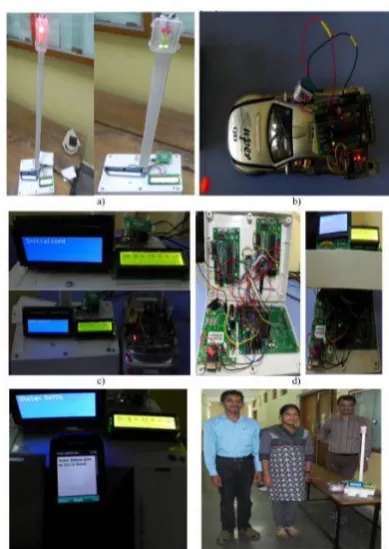
switch is pressed, it will transmit the signal. The signal contains unique id and security code. The transmitter contains PIC16F877A microcontroller and ZigBee module. The microcontroller sends the commands and data to the ZigBee via serial communication. Second part is the receiver, which is placed at traffic pole. It also contains PIC16F877A microcontroller and ZigBee module. The receiver compares the security code received to the security code present in its database. If it matches, then it will turn the green light on. For testing purpose, we used short range RFID reader in our prototype. First, the receiver part is turned on. The red and green signal will be on for 10 seconds duration and orange light will be on for 2 seconds duration one after the other. Secondly, we bring the RFID of stolen vehicle into the range of RFID reader. Then the signal will turn to red for duration of 30 seconds and a SMS is received.Thirdly,we bring 12 RFIDs into the rangeof RFID reader,andthen the greenlight duration will change to 30 seconds. Fourthly, we bring an emergency vehicle carrying ZigBee transmitter into the range of ZigBee receiver, and then the traffic light will change to green till the receiver receives the ZigBee signal as shown in Figure 4. Figure 5 shows the images of different components and highlighted features of the proposed work. Figure 5.a shows the signal pole installed in junction. In the default condition, red and green light will set for 10 seconds. The time period will be varied according to the traffic conditions, stolen vehicle, and emergency vehicle. Figure 5.b shows the transmitter part is placed in the ambulance. It transmits ZigBee signal continuously. Figure 5.c shows the LCD display status at different conditions (in that figure one is normal conjunction image(traffic signal running as per the default time period)and another one is LCD display status, when an ambulance coming near to junction. Figure 5.d shows the actual connections of different components like RFID, GSM, ZigBee, interfacing different microcontrollers. Figure 5.e shows the status updated at the time of stolen vehicle is found. The stolen vehicle RFID number should be updated in the database. If stolen vehicle is found,
then it will immediately turn on red light in the signal. It sends immediately a message to authorized person. Figure 5.f shows the working model of the proposed work.
V.
CONCLUSION AND ENHANCEMENTSWith automatic traffic signal control based on the traffic density in the route, the manual effort on the part of the traffic policeman is saved. As the entire system is automated, it requires very less human intervention. With stolen vehicle detection, the signal automatically turns to red, so that the police officer can take appropriate action, if he/she is present at the junction. Also SMS will be sent so that they can prepare to catch the stolen vehicle at the next possible junctions. Emergency vehicles like ambulance, fire trucks, need to reach their destinations at the earliest. If they spend a lot of time in traffic jams, precious lives of many people may be in danger. With emergency vehicle clearance, the traffic signal turns to green as long as the emergency vehicle is waiting in the traffic junction. The signal turns to red, only after the emergency vehicle passes through. Further enhancements can be done to the prototype by testing it with longer range RFID readers. Also GPS can be placed into the stolen vehicle detection module, so that the exact location of stolen vehicle is known. Currently, we have implemented system by considering one road of the traffic junction. It can be improved by extending to all the roads in a multi-road junction.
VI.
REFERENCES1. G Varaprasad and R. S. D. Wahidabanu, ―Flexible routing algorithm for vehicular area networks,‖ in Proc. IEEE Conf. Intell. Transp. Syst. Telecommun., Osaka, Japan, 2010, pp. 30– 38.
3. K Sridharamurthy, A. P. Govinda, J. D. Gopal, and G. Varaprasad, ―Violation detection method for vehicular ad hoc networking,‖ Security Commun. Netw., to be published. 4. M Abdoos, N. Mozayani, and A. L. C. Bazzan,
―Traf?c light control in non-stationary environments based on multi agent Q-learning,‖ in Proc. 14th Int. IEEE Conf. Intell. Transp. Syst., Oct. 2011, pp. 580–1585.
5. ZigBee Speci?cations, ZigBee Alliance IEEE Standard 802.15.4k2013, 2014. [Online]. Available:
http://www.zigbee.org/Speci?cations.aspx [6] Traf?c Congestion in Bangalore—A Rising Concern. [Online]. Available: http://www.common?oor.com/guide/traf?c- congestion-in-bangalore-arising-concern-27238.html, accessed 2013.
6. A K. Mittal and D. Bhandari, ―A novel approach to implement green wave system and detection of stolen vehicles,‖ in Proc. IEEE 3rd Int. Adv. Computer., Feb. 2013, pp. 1055–1059. 7. S Sharma, A. Pithora, G. Gupta, M. Goel, and M. Sinha, ―Traf?c light priority control for emergency vehicle using RFID,‖ Int. J. Innov. Eng. Technol., vol. 2, no. 2, pp. 363–366, 2013. 8. R Hedge, R. R. Sali, and M. S. Indira, ―RFID
and GPS based automatic lane clearance system for ambulance,‖ Int. J. Adv. Elect. Electron. Eng., vol. 2, no. 3, pp. 102–107, 2013.
9. P. Sood. Bangalore Traf?c Police-Preparing for the Future. [Online]. Available: http://www.intranse.in/its1/sites/default/?les/D 1-S2-, accessed 2011.
10. Traf?c Management Centre. [Online].
Available: http://www.
bangaloretraf?cpolice.gov.in/index.php? option=com_content&view=
article&id=87&btp=87, accessed 2014.
11. G. Varaprasad, ―High stable power aware multicast algorithm for mobile ad hoc networks,‖ IEEE Sensors J., vol. 13, no. 5, pp. 1442–1446, May 2013.