Available online: https://pen2print.org/index.php/ijr/ P a g e | 1284
Controller Design for Temperature Control of Heat Exchanger
System: Simulation Studies
Miss. Mayuri H. More
1, Dr. M.G. Poddar
21(Department of Post Graduation (Control System Engineering), M. B. E. Society’s College of Engineering Ambajogai, India)
2(Department of Post Graduation (Control System Engineering), M. B. E. Society’s College of Engineering Ambajogai, India)
Keywords : Shell and tube heat exchanger system, Feed-forward controller, Feedback controller, PI controller
and Feedback plus Feed forward controller.
1. Introduction
Heat exchanger is mostly used in chemical processes to transfer heat from a hot fluid through a solid wall to a
cooler fluid. Shell and tube heat exchangers are commonly used in type temperatures and pressures. A shell and
tube heat exchanger is a double-pipe configuration. In shell and tube heat exchanger one fluid flows through the
tubes and another fluid flows within the space between the tubes and the shell [1]. The PI controller is
implemented and, compares the output with the set point and then it gives a necessary command to the final
control element via the actuator unit. We have to design a controller for temperature control of a heat exchanger
system by calculating the transfer functions of Feedback, Feed-forward, and Feedback plus Feed-forward
controller.
Apart from the introductory section, in this paper have four different sections. In section I, the heat exchanger
system and the controllers which are used in this paper are introduced. In section II, the basic heat exchanger
and mathematical modeling of the system are designed in Materials and Methods. In section III, results and Abstract : Heat exchanger system is mostly used in chemical plants due to its property to sustain temperature
and pressure. The main aim of a heat exchanger system is to heat transfer from a hot fluid to a cooler fluid. In
this Temperature control of heat exchanger system we design different controllers such as Feedback, Feed
forward and Feedback plus Feed forward controllers. Analyzing the performance of those controllers and
regulate the temperature of outlet fluid of a shell and tube heat exchanger to a certain reference value. The
transient performances of these controllers are analyzed and the best controller is found out. From the
simulation results, it is found out that the feedback plus feed-forward controller has a superior performance than
Available online: https://pen2print.org/index.php/ijr/ P a g e | 1285
discussion provide simulation results for different control techniques and the best controller design technique is
identified from the transient response performance and error criteria. In section IV, How we can conclude the
best controller.
2. Materials and Methods
In this section develop the mathematical model of the system by calculating the transfer function of the different
controllers. By developing control algorithms of different controllers like feed-forward, feedback PI controller
and the combination of feedback plus feed-forward controller. First, discuss a basic heat exchanger system.
Developing a mathematical model of the heat exchanger system and calculate the first order plus dead time
model (FOPDT) of the system.
2.1 System Description
The thermocouple is used to measure the temperature of the outgoing fluid and the output of the thermocouple
(voltage) is sent to the transmitter unit, which finally converts the thermocouple output into a standardized
signal in the range of 4-20 MA. The controller implements the control algorithm, compares the output with the
set point and then Different assumptions have been considered in this paper. The first assumption is that the
inflow rate and the outflow rate of fluid are the same so that the fluid level is maintained constant in the heat
exchanger. The actuator unit is used to current to pressure converter and the final control unit is an air to open
Available online: https://pen2print.org/index.php/ijr/ P a g e | 1286 Fig. 1 Heat Exchanger System Control Scheme
2.2 Mathematical Modeling
2.2.1 Heat Exchanger Process
Fig 2 Stirring Reactor with Heat Exchanger
A chemical reactor called "stirring tank" is given below. The liquid inflow delivers liquid to be mixed in the
tank. The tank liquid maintained at a constant temperature by varying the amount of steam supplied to the heat
exchanger (bottom pipe) via its control valve. Variations in the temperature of the inlet flow are the main source
of disturbances in this process [10].
Available online: https://pen2print.org/index.php/ijr/ P a g e | 1287
To derive a first-order-plus-dead-time model of the heat exchanger system, inject a step disturbance in valve
voltage V and record the effect on the tank temperature T over time. The measured response in normalized units
is shown below [11]:
Fig. 3 Measured Responses to Step Change In Steam Valve Voltage
The values and are the times where the response attains 28.3% and 63.2% of its final value.
Using these values to estimate the time constant tau and dead time theta for the heat exchanger:
Available online: https://pen2print.org/index.php/ijr/ P a g e | 1288 = 3/2 *( )
=
Verify these calculations by comparing the first-order-plus-dead-time response with the measured response:
;
(1)
Available online: https://pen2print.org/index.php/ijr/ P a g e | 1289 Fig. 4 Open-Loop Process
3. Control Algorithms
3.1 PI Controller Action Mode
As the name indicates PI controller is combination of proportional controller and integration controller. The
output of this control action mode is proportional to combination of the P & I control action.
Mathematically output of this mode is given by:
(2)
In this control action mode the proportional mode provides one-to-one correspondence and integral mode
eliminates the inherent offset.
4. Feed-forward control
The feed forward controller F is used to measure the inflow temperature to adjust the steam valve opening
(voltage V).
Fig. 5 Feed forward Control
Calculate the overall transfer from temperature disturbance d to tank temperature T is
Available online: https://pen2print.org/index.php/ijr/ P a g e | 1290 Disturbance rejection requires
(4)
5. Feedback Control
The transfer function
(5)
Models how a change in the voltage V, affects the tank temperature T, while the transfer function
(6)
To regulate the tank temperature T around a given set point Tsp, we can use the following feedback architecture
to control the valve opening (voltage V).
Fig. 6 Feedback Control
In this configuration, the proportional-integral (PI) controller
Available online: https://pen2print.org/index.php/ijr/ P a g e | 1291
Calculates the valve voltage V based on the gap Tsp-T between the desired and measured temperatures. By
using the ITAE formulas to pick adequate values for the controller parameters:
, (8)
(9)
To see how the ITAE controller performs, close the feedback loop and simulate the response to a set point
change:
6. Combined Feedback Plus Feed-forward Control
Feedback control is good for set point tracking in general, while feed-forward control can help with rejection of
measured disturbances. Look at the benefits of combining both schemes. The corresponding control architecture
is shown below:
Available online: https://pen2print.org/index.php/ijr/ P a g e | 1292
7. Results and Discussion
Fig. 8 Feedback plus Feed forward System
In this feedback plus Feed forward system, voltage v is increases and we get the desired response of the system.
It means voltage V is achieved in less time period. In above fig 5.4 valve is open and steam is flowing into the
tank, we can observe that the steam is red in color and tank liquid is heated. As we know the blue liquid is
changed in pink. Because of the feedback plus Feed forward system we can achieve the desired output
.
Controller Overshoot Settling Time
Feed-forward 0% 97.8 sec
Feedback 15.87% 105.5 sec
Feedback plus Feed-forward 0.33% 85.6sec
Available online: https://pen2print.org/index.php/ijr/ P a g e | 1293
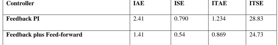
Controller IAE ISE ITAE ITSE
Feedback PI 2.41 0.790 1.234 28.83
Feedback plus Feed-forward 1.41 0.54 0.869 24.73
Table 2: Results for error indices of controller
8. Conclusion
This paper implements a different controller (Feedback, Feed-forward, and Feedback plus Feed-forward
controller) to control the outlet temperature of a shell and tube heat exchanger system. The mathematical model
of the heat exchanger is developed using experimental data and the process model is used to develop a
respective controller. The performances of different controllers are evaluated using transient characteristics and
error indices. From the simulation results, it is found that the feedback plus feed-forward has a superior
performance than feedback controller. The feedback controller implemented using classical PI controller shows
a higher degree of overshoot and settling time whereas the feedback plus feed-forward control negates the
overshoot and has a manageable settling time.
References
[1] Anton Sodja et.al, "Some Aspects of Modeling of Tube-and-Shell Heat-Exchangers," in Proc
of 7th Modelica Corif-, Italy, pp. 716-721, Sep 2009.
[2] L. Ljung, System identification. (Springer, 1998).
[3] V. R. Segovia, T. Hagglund, and K. ¨ Astr ˚ om, ¨ “Measurement noise filtering for pid controllers,” Journal of Process Control, vol. 24, no. 4, pp. 299–313, 2014.
Available online: https://pen2print.org/index.php/ijr/ P a g e | 1294
[5] K. H. Ang, G. Chong, and Y. Li, “Pid control system analysis, design, and technology,” IEEE
Transactions on Control Systems Technology, vol. 13, no. 4, pp. 559–576, 2005.
[6] W. Tan, J. Liu, T. Chen, and H. J. Marquez, “Comparison of some well-known pid tuning
formulas,” Computers & chemical engineering, vol. 30, no. 9, pp. 1416–1423, 2006.
[7] B. W. Bequette, Process control: modeling, design, and simulation (Prentice Hall
Professional, 2003).
[8] D. Seborg, T. F. Edgar, and D. Mellichamp, Process dynamics & control ( John Wiley &