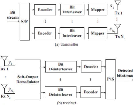
Volume 4, No. 9, July-August 2013
International Journal of Advanced Research in Computer Science
RESEARCH PAPER
Available Online at www.ijarcs.info
ISSN No. 0976-5697
Space time Block Coding for MIMO systems over a Raleigh fading Channels with Low
Decoding Complexity
Shriddha Shrivastava*1, Jaikaran Singh2, MukeshTiwari3
Department of Electronics
Shri SatyaSai Institute of Science & Technology Bhopal , India
,
Abstract-The demand for mobile communication systems with high data rates has dramatically increased in recent years. New methods are necessary in order to satisfy this huge communications demand, exploiting the limited resources such as bandwidth and power as efficient as possible. MIMO systems with multiple antenna elements at both link ends are an efficient solution for future wireless communications systems as they provide high data rates by exploiting the spatial domain under the constraints of limited bandwidth and transmit power. Space-Time Block Coding (STBC) is a MIMO transmit strategy which exploits transmit diversity and high reliability. This paper presents a detailed study of Different space-time block coding (STBC) schemes including Alamouti’s STBC for 2 transmit antennas and 2 receive antennas as well as orthogonal STBC for 3 and 4 transmit antennas and 3 and 4 receive antennas are explored. Orthogonal space–time block codes (OSTBC) from orthogonal designs with maximum-likelihood (ML) decoding achieve low decoding complexity and full diversity. Finally, these STBC techniques are implemented in MATLAB. And ccomparative analysis for performance according to their bit error rates using M-ary PSK, QPSK, QAM, modulation schemes at the transmitter side in a Raleigh fading channel.
Keywords: MIMO system, orthogonal space time block code, digital modulation, ML Detector
I. INTRODUCTION
Space–time block coding is a technique used in across a number of received versions of the data to improve the reliability of data-transfer. The fact that the transmitted signal must traverse a potentially difficult environment with corrupted by of the received copies of the data will be 'better' than others. This redundancy results in a higher chance of being able to use one or more of the received copies to correctly decode the received signal. In fact,all
the copies of the received signal in an optimal way to extract as much information from each of them as possibleSpace-time block codes operate on a block of input symbols, producing a matrix output whose columns represent time and rows represent antennas. In contrast to single-antenna block codes for the
Rayleigh fading channel, space-time block codes do not generally provide coding gain, unless concatenated with an outer code. Their main feature is the provision of full diversity with a very simple decoding scheme. Multi-antenna communication has attracted much interest for its effectiveness in combating fading channels. A variety of space-time coding strategies for multi-antenna systems have been proposed in the past decade. For example, space-time block coding were formally analysed in [1] and [2], and the design criterion for achieving full diversity with Maximum Likelihood (ML) decoding was derived.
However, the complexity of ML decoding is usually prohibitive when the numbers of receive and transmit antennas increase. Suboptimal decoding such as using linear minimum mean square error (MMSE) receivers was studied in [3] However, it suffers from extremely high detection
complexity because an exhaustive search should be carried out over all possible candidate symbol vectors. In linear equalization based schemes [3], zero forcing (ZF) or minimum mean square error (MMSE) criterion is used to determine the estimated symbol vector.
II. PRINCIPLES OF MIMO
A. MIMO System Model:
The idea behind MIMO is that the transmit antennas at one end and the receive antennas at the other end are connected and combined in such a way that the bit error rate (BER), or the data rate for each user is improved. MIMO has the capacity of producing independent parallel channels and transmitting multi path data streams and thus meets the demand for high data rate wireless transmission. This system can provide high frequency spectral efficiency and is a promising approach with tremendous potential.
Figure 1.3 shows a simple representation of a MIMO system with transmit antennas and receive antennas.
The channel for a MIMO system can be represented by
=
In the encoding and transmission sequence, at a given symbol period, signals are transmitted through two antennas. The signal transmitted from the first antenna is denoted by and from the second antenna by . During the next symbol period, is transmitted from the first antenna, and
is transmitted from the second antenna, where * is the complex conjugate operation. The rows of each coding scheme represents a different time instant, while the columns represent the transmitted symbol through each different antenna. In this case, the first and second rows represent the transmission at the first and second time instant respectively.
The encoding process is done in space and time (space-time coding). The received signal at the receiver in the case of (2x2) MIMO system is given by
Where is the channel matrix and are complex random variables representing receiver thermal noise and interference.
Figure 1.3 shows the 2 x MIMO system; where represents the channel between the transmitters to the receiver. When ( > 2), with the number of channels, number of RF chains required to process the received signal, the channel matrix also gets increased causing the increase of complexity and cost of the system. So an optimum antennas selection algorithm is used to select a set of receive antennas where we can get maximum signal strength and maximum achievable rate. Antenna selection algorithms choose the best receive antenna subset according to the channel response. The channel matrix corresponding to these antennas is generated by deleting the rows associated with the unselected antenna. From this the received signals corresponding to these selected antennas are used for the detection of the signal.
III. DIGITAL MODULATION
A. M-ary Encoding:
M-ar yis a term derived from the word binary. M
simply represents a digit that corresponds to the number of conditions, levels, or combinations possible for a given number of binary variables. For example, a digital signal with four possible conditions (voltage levels, frequencies, phases, and so on) is an M-ary system where M = 4. If there are eight possible conditions, M= 8 and so forth. The
number of bits necessary to produce a given number of conditions is expressed mathematically as
Where N = number of bits necessary
M = number of conditions, levels, or combinations possible with N bits
the number of conditions possible with N bits as
For example, with one bit, only = 2 conditions are possible. With two bits, = 4 conditions are possible, with Three bits, = 8 conditions are possible, and so on.
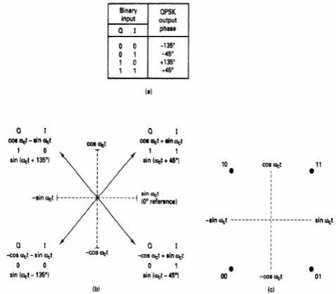
a. Quaternary Phase-Shift Keying:
QPSK is an M-ary encoding scheme where N = 2 and
M= 4 (hence, the name "quaternary" meaning "4"). A QPSK modulator is a binary (base 2) signal, to produce four different input combinations,: 00, 01, 10, and 11.
Therefore, with QPSK, the binary input data are combined into groups of two bits, called digits. In the modulator, each digit code generates one of the four possible output phases (+45°,+135°, -45°, and -135°).
Figure 2-18 Qpsk Modulator: (A) Truth Table; (B) Phaser Diagram; (C) Constellation Diagram
IV. ENCODING OF SPACE TIME CODING
A. Space-Time Block Coding:
B. Alamouti’s STBC:
In [5], Alamouti published his technique on transmit diversity. Historically, Alamouti’s scheme was the first STBC [5].The The Alamouti STBC scheme uses two transmit antennas and Nr receive antennas and can accomplish a maximum diversity order of 2Nr [5]. Moreover, the Alamouti scheme has full rate (i.e. a rate of 1) since it transmits 2 symbols every2 time intervals. Next, a description of the Alamouti schemes provided for both 1 and 2 receive antennas, followed by general expression for the decoding mechanism for the case of Nr receive antennas
a. Description: As mentioned earlier, Alamouti STBC uses two transmit antennas regardless of the number of receive antennas. The Alamouti scheme encoding operation is given by [5]. In this paper, the rows of each coding scheme represents a different time instant, while the columns represent the transmitted symbol through each different antenna. In this case, the first and second row represents the transmission at the first and second time instant respectively. At a time t, the symbol s1 and symbol s2 are transmitted from antenna 1and antenna 2 respectively. Assuming that each symbol has duration T, then at time t + T, the symbols –s*and s*where (.)* denotes the complex conjugate, are transmitted from antenna 1 and antenna 2 respectively.
b. Case of 1 Receive Antenna: The reception and decoding of the signal depends on the number of receive antennas available. For the case of one receive antenna, the receive signals are [5]:
r₁⁽¹⁾ = r₁(t)= h₁₁s₁ +h₁₂s₂ + =r₁(t+T) =
where is the received signal at antenna 1, is the channeltransfer function from the transmit antenna and the receive antenna is a complex randomvariable representing noise at antenna 1, and denotes xat time instant k (i.e. at time t + (k-1) T).Before the received signals are sent to the decoder, they are combined as follows [5]:
and substituting (2) in (3) yields:
where is the squared magnitude of the channel transfer function .The calculated and are then sent to a MaximumLikelihood (ML) decoder to estimate the transmitted symbols s1 and s2 respectively[5].
c. Case of 2 Receive Antennas: For the cases of two receive antennas, the received symbol are[5]:
and the combine signals are [5]:
Which, after substituting becomes;
C. Orthogonal Space-Time Block Codes:
a. Orthogonality:
STBC’S as originally introduced, and as usually studied, ar designed such that the columns taken from the coding matrix is orthogonal.
The Alamouti scheme discussed in Section III-A is part of a general class of STBC’S known as Orthogonal Space-Time Block Codes (OSTBC’S) [6]. The authors of [1] apply the mathematical framework of orthogonal designs to construct both real and complex orthogonal codes that achieve full diversity. For the case of real orthogonal codes, it has been shown that a full rate code can be constructed [1]. However, for the case of complex orthogonal codes, it is unknown if a full rate and full diversity codes exist for Nt> 2 [1].Complex modulation techniques are of interest in this paper and therefore real orthogonal codes are not discussed. In next sections, the full diversity complex orthogonal codes presented in [1] for different rates are briefly introduced.
a) Orthogonal Space-Time Block Codes for Nt = 3: For the case of 3 transmit antennas, Tarokh et al. construct block codes for the with 1/2 and 3/4 coding rate and full diversity3Nr.
a) Nt = 3 with Rate 1/2: The full diversity, rate 3/4 code for Nt = 3 is given by
These codes achieve rate-1/2 and rate-3/4 respectively. These two matrices give examples of why codes for more than two antennas must sacrifice rate — it is the only way to achieve orthogonality. One particular problem with C3,3 / 4 is
that it has uneven power among the symbols it transmits. This means that the signal does not have a constant and that the power each antenna must transmit has to vary, both of which are undesirable. Modified versions of this code that overcome this problem have since been designed.
b. Four Transmit Antennas
V. DECODING OF STB’S
A. Maximum Likehood Decoder:
One particularly attractive feature of orthogonal STBC’S is th achieved at the receiver with onl to consider a decoding method, a model of the wireless communications system is needed.
At time t, the signal received at antenna j is:
,
where αij is the path gain from transmit antenna i to
receive antenna j, is the signal transmitted by transmit
antenna i and is a sample of
The maximum-likelihood detection rule decision variables
Where δk(i) is the sign of si in the kth row of the coding
matrix, εk(p) = q denotes that sp is (up to a sign difference),
the (k,q) element of the coding matrix, for i = 1,2...nT and
then decide oi that satisfies
,
With the
appearance, this is a simple, linear decoding scheme that provides maximal diversity.
VI. SIMULATIONS
Simulations are done in MATLAB using the Rayleigh channel model We simulate and , for the case of Nr = 1 up to Nr = 4. We modulate using QPSK, M-ary PSK and 64- QAM Gray mapping constellations. For each sample, blocks of 1000 symbols are simulated until at least 100 bit errors are obtained, or until 1000 blocks are simulated. The simulation is stopped when the SNR reached 20dB or after simulating 1000 blocks without errors.
Figure-1 Bit errer rate versus Eb/N(db) of OSTBC for Nr =2
VII. RESULTS AND ANALYSIS
We study the performance of each block code discussed earlier for the different cases of constant Nr, Nt, rate, and diversity order.
For the case of Nr constant, we fix Nr= 2. The result is shown in Figure 1$2. As expected, for each different code blocks, the performance degrades as more bits per symbol are transmitted. It can be observed that for a particular modulation and high SNR, the best performance is obtained by followed by and . However the results are that the best performance at low SNR is obtained by followed by
, and .
The BER curve for the case of keeping Nt = 4 constant while varying Nr from 1 to 4 for different modulations is depicted in Figure 3. It can be observed that the BER reduces if the number of receiver antenna is increases but reduce the energy per receive antenna. and it also observed that for particular block code, QPSK modulation give the more efficient result than the M-PSK and QAM.
Figure-2 Bit errer rate versus Eb/N(db) of OSTBC for Nr =2
Figure-3 Bit errer rate versus Eb/N(db) of OSTBC for Nr =3
VIII. CONCLUSION
that allow low-complexity with ML decoding. We then discussed block codes schemes with different code rates for the cases of 3 and 4 transmit antennas. Moreover, we optimized the rate-one and rate-1/2 design to achieve the minimum BER for Raleigh fadingchannel realization when the information symbols are drawn from QPSK,M-PSK QAM constellations. The encoding and decoding algorithms for each were both presented. It was observed that higher diversity gain does not always imply better performance. This was observed when outperformed for Nr = 2. Also, we observed BER reduces if the number of receiver antenna is increases but reduce the energy per receive antenna. and it also observed that for particular block code, QPSK modulation give the more efficient result than the M-PSK and QAM.Finally, we conclude that it is preferable to use a low constellation order for OSTBC with high code rate and low code rate.
IX. REFERENCES
[1]. B. A. Sethuraman, B. S. Rajan, and V. Shashidhar, “Full-diversity,high-rate space-time block codes from division algebras," IEEE TransInform. Theory, Vol. 49, no. 10, pp. 2596-2616, Oct. 2003
[2]. F.-T. Hsu and H.-J. Su, “Linear dispersion space-time codes for multiuser systems with low decoding complexity," in Proc. IEEE PIMRC,Cannes, France, Sept. 2008
[3]. A. Fasano and S. Barbarossa, “Iterative MMSE decoder for traceorthogonal space-time coding," in Proc. IEEE ICASSP, Toulouse,France, May 2006.
[4]. G. Tsoulos, MIMO system technology for wireless communications,CRC Press, 2006.
[5]. S. Alamouti, “A simple transmit diversity technique for wireless communications,”IEEE Journal on selected areas in communications, vol. 16,no. 8, pp. 1451–1458, 1998
[6]. L. Cortes-Pena, “Orthogonal Space-Time Coding Matlab SourceFiles,” Software on-line: http:// users.ece.gatech.edu/_cortes/STBCMatlab.html, 2009.
[7]. A. Fasano and S. Barbarossa, “Trace-orthogonal space-time coding,"IEEE Trans. Signal Processing, vol. 56, no. 5, pp. 2017-2034, May2008.
[8]. H. Niu and Ngo, “Diversity and Multiplexing Switching in 802.11 nMIMO Systems,” in Signals, Systems and Computers, 2006.ACSSC’06.Fortieth Asilomar Conference on, 2006, pp. 1644–1648.
[9]. P. Elia, F. Oggier, and P. V. Kumar, “Asymptotically optimalcooperativewireless networks with reduced signaling complexity," IEEE J. Select.Areas Commun., vol. 25, no. 2, pp. 258-267, Feb. 2007
[10]. “IEEE P802.11n/D5.0,” May 2008