R e s e a r c h
Open Access
Interference cancelation scheme with
variable bandwidth allocation for universal
filtered multicarrier systems in 5G networks
Lei Chen
1,2,3*and J. G. Yu
1,2Abstract
The universal filtered multicarrier (UFMC) is an appealing technique to eliminate out-of-band emission (OOBE) for fifth-generation (5G) networks. However, its signals that are modulated to the carriers, which are on the edges of one subband, are influenced by the filter. In this paper, an interference cancelation scheme is proposed to suppress the interference and to improve the multiuser system performance. Here, interference cancelation subcarriers are inserted on the edges to reduce the filter interference. This scheme ensures that the operating subregion or subband supports the variable bandwidth allocation to meet the requirements of 5G networks. Simulation results show that the bit error rate (BER) performance improves by 4 and 7 dB compared with that of the conventional UFMC when the
corresponding Eb/N0 is 15 and 20 dB. Comparisons with both the standard OFDM and the GB OFDM are also reported. The results demonstrate that the proposed UFMC scheme outperforms the other two systems, especially compared with the GB OFDM system under the condition of the same spectral efficiency.
Keywords: Universal filtered multicarrier, Interference cancelation, Multiuser access, Bandwidth allocation, Carrier frequency offset
1 Introduction
One of the main prospective scenarios of 5G networks is machine-type communications (MTC) [1, 2], where the devices are generally one order of magnitude larger than human communication users. These devices and their corresponding traffic will generate pieces of spectrum that will be a primary challenge of 5G networks [3]. Therefore, 5G networks have to support high bit rate traffic with high spectral efficiency. The well-known orthogonal frequency division multiplexing (OFDM) is widely applied in mul-tiuser systems because of its robustness and easy imple-mentation based on fast Fourier transform (FFT) algo-rithms. Nevertheless, the predicted application scenarios of 5G networks present challenges where the OFDM can be applied in only a limited way, for example, the sporadic communication of MTC devices in the Internet of things (IoT), which makes it difficult to maintain the orthog-onality among subcarriers in the strict synchronization
*Correspondence: [email protected]
1School of Electronic and Engineering, Beijing University of Posts and Telecommunications, 100876 Beijing, China
Full list of author information is available at the end of the article
process [1]. The OFDM symbol with cyclic prefix (CP) presented low spectral efficiency when used to solve the low latency requirements in tactile Internet applications [4]. Additionally, the high OOBE of OFDM represented a challenge for random and dynamic spectrum access sys-tems [5]. These problems make OFDM vulnerable when solving frequency misalignments in multiuser scenarios, and the system is affected seriously by intercarrier inter-ference (ICI).
To overcome these difficulties, several new wave-forms have attracted the attention of researchers, includ-ing UFMC, filter-bank-based multicarrier (FBMC), and generalized frequency division multiplexing (GFDM), because these waveforms have much lower sidelobe levels than that of OFDM systems. GFDM is suitable for non-contiguous frequency band allocation because it adopts a shortened CP via the tail biting technique [6, 7]. FBMC can make the sidelobes much weaker and the intercar-rier interference issue far less crucial compared to those of OFDM by applying a filter to each of the subcarriers [8–10]; however, it is unfit for short bursts, such as those as in MTC, because of the long filter length [1, 11]. By
contrast, to achieve relatively flexible band allocation, the UFMC waveform, which starts with an OFDM signal and includes the advantages of filtered OFDM and FBMC, was proposed [12, 13]. The UFMC is performed on groups of adjacent subcarriers by filtering to reduce both the side-lobe levels and intercarrier interference that result from poor time/frequency synchronization [3]. Moreover, the filter length of UFMC systems is shorter than that of FBMC systems due to their different bandwidths. There-fore, the UFMC is considered to be an appealing tech-nique for 5G networks. Moreover, there are techtech-niques to improve the performance and application of UFMC systems, for example, the performance evaluation in a sce-nario with relaxed synchronization [14], a frame structure and design targeting IoT provision [15], a field trial for performance evaluation [16], and filter optimization by considering both the carrier frequency and timing off-set [17] or using the signal over in-band distortion and out-of-band leakage ratio [18]. In this paper, we focus on the interference in one subband and present a scheme to improve the system performance.
An interference cancelation method is proposed for UFMC systems in this paper to further decrease the inter-ference in one subband. This method, which is based on the ICI cancelation method used in OFDM systems, can be flexibly configured according to the specific band-width requirements of multiusers in 5G networks. The ICI cancelation method performs much better than the method used in standard OFDM systems [19]. However, the bandwidth efficiency is reduced several fold owing to the redundant modulation in the entire band. Based on the analysis of filter interference, we find that the subcar-riers on the edges of a subband are greatly influenced by the existence of a transition zone, especially in low-cost devices with low-order filters. This phenomenon inspires us to modulate the subcarriers on the edges with the ICI cancelation method. Then, an interference cancela-tion method is proposed for UFMC systems to restrain the edge interference and prevent significant reductions in spectral efficiency.
The rest of this paper is organized as follows. First, a summary of related work is given in Section 2. Then, we present a modified system model for UFMC systems and its corresponding interference cancelation method in Section 3. Furthermore, Section 4 analyzes the simu-lated BER performance based on the proposed scheme of UFMC systems under the condition of multiuser access. We also compare the performance with those of con-ventional UFMC, guard band (GB) OFDM, and standard OFDM. Finally, the conclusions are presented in Section 5.
2 Related work
A few schemes have been proposed to mitigate the inter-ference caused by time/frequency synchronization error
in UFMC systems. One study [20] presented a novel filter optimization technique with both low complexity and high throughput to reduce inter-subband interfer-ence (ISBI). Two methods were applied: spectrum shap-ing with low complexity and carrier insertion between two filters. The filter optimization method provided a better signal-to-interference ratio (SIR) than that of the original method, improving the robustness against ISBI.
Additionally, a similar scheme to reduce ISBI was pro-posed in [21], where the authors incorporated active interference cancelation (AIC) into the UFMC system to further reduce inter-subband interference and enable highly reliable communication. AIC is widely applied in multiband cognitive OFDM system by inserting specific subcarriers on both sides of the primary user to actively eliminate interference between primary and secondary users.
By contrast, Lei Zhang et al. concentrated on time syn-chronization by bringing the CP into UFMC systems. The authors analyzed the conditions for interference-free one-tap equalization for an imperfect transceiver; then, the corresponding channel equalization algorithms were proposed and validated by simulations [22].
Additionally, [23] established a multiservice framework based on a subband-filtered multicarrier system to ana-lyze the desired signal, intersymbol interference (ISI), ICI, ISBI, and noise. Inter-serviceband interference can-celation algorithms were also proposed by precoding the information symbols at the transmitter. In this process, a certain GB was inserted between different types of services to mitigate the interference.
Although all the above schemes provide better perfor-mance than that of conventional systems for ICI, ISBI, and ISI reduction, researchers have not considered the effect of the filter in the subband, which also results in system performance degradation due to partial loss of information. Therefore, we concentrate on this situation and propose an interference cancelation scheme to further improve system performance.
3 System model and proposed interference cancelation scheme
3.1 UFMC system model
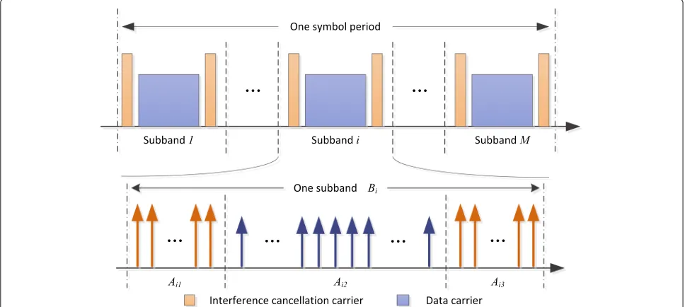
Figure 1 shows the UFMC system model and our proposed interference cancelation scheme. Compared with stan-dard OFDM systems, the entire band of this model withN
subcarriers is divided intoMsubbands, which correspond toMpieces of equipment. Each subband can be allocated to either one piece of equipment or physical resource block (PRB) in LTE, and each piece of equipment occupies a different amount of consecutive subcarriers determined by its service type [24]. Additionally, the subband sidelobe level can be significantly suppressed by using a bandpass filter (BPF). However, filtering has some negative effects on a certain number of subcarriers, especially on the edges of the subband. Thus, the proposed scheme is shown in Fig. 1.
The process of modulation-demodulation shown in Fig. 1, including the transmitter and receiver, is as follows. At the transmitter, the modulation control unit uses sub-carrier modulation strategy to generate interference can-celation and data subcarriers to reduce the interference; then, by means of an N-point inverse discrete Fourier transform (IDFT) converter, the frequency-domain sub-band signalXi(k)is converted into a time-domain signal xi(n), with output lengthN. After the IDFT operation on each subband, the signal passes to the BPF with length
L, so the length of a UFMC symbol becomesN+L−1 because of the convolution process. Both the Doppler effect due to moving equipment and local oscillator mis-alignment between transceivers have to be considered to model the carrier frequency offset (CFO), and the trans-mitted signal of the UFMC is generated by summing all filtered subband signals. From the view of the receiver, a 2N-point discrete Fourier transform (DFT) is performed after appending zeros, and a subband allocation unit is used to estimate the symbols in individual subbands.
Eventually, the demodulation control unit adopts a simi-lar strategy as that of the modulation block to complete the signal estimations for both the interference cancela-tion and data subcarriers. A mathematical analysis of the above process is presented in the following.
For an arbitrary ith subband Bi(i ∈[ 1 : M]), the fre-quency domain signalXi(k)of theith equipment is trans-formed to the time domain xi(n) by the IDFT, and its expression is
xi(n)= 1
N
k∈Bi
Xi(k)ej 2π
Nnk, n=0, 1,· · ·,N−1 (1)
Then, the complete original signal in the frequency domainX(k) is the sum of eachXi(k)
X(k)= M
i=1
Xi(k) (2)
By filtering through BPF, the output signalti(n) is the result of discrete linear convolution between the filter impulse responsefi(n)and the time-domain signalxi(n). As previously mentioned, fi(n) has length L, and ti(n) has lengthN+L−1. Therefore, the formula of UFMC symboly(n), in consideration of CFO, is expressed as
y(n)= M
i=1
ci(n)·ti(n)= M
i=1 ci(n)·
xi(n)∗fi(n)
(3)
whereci(n)is the time-domain frequency-offset expres-sion of theith subband with the same length asti(n), and * denotes the linear convolution operator. In the frequency domain,Cˆi(k)is the 2N-point DFT ofci(n)and can be presented as
ˆ
where ε denotes the relative CFO for subband i. This equation shows the frequency offset acting on subcarrierk, which is caused by CFO, that damages the orthogonality between carriers, that is, the ICI.
On the receiving end, a 2N-point DFT is used to perform the conversion from a time-domain signal to a frequency-domain signal. Then, we can derive the received symbolsYˆ(k)as
ˆ
E(k)is an additive noise sample of subcarrierk.
To gradually illustrate the relationship betweenN-point sequenceXi(k)andYi(k)and separate the desired signal part from the interference part in Eq. (5), we first derive
ˆ
Equation (6) indicates that the odd subcarriers con-tain part of the signal energy and the interference, which comes from other subcarriers because of the 2N-point DFT. Additionally, the 2N-point received sequence has the same conditions. By combining 2N-point signalYˆ(k) with the relationship betweenN-point DFT and 2N-point DFT, we obtain the expression forN-point received signal
Y(k)
Then, we consider the interference in only one subband because the ISBI from other subbands is suppressed suf-ficiently by filters. To simplify the analytical model, all the signals in odd subcarriers are ignored. According to Eqs. (5), (6), and (7), we separate the desired signal from the received symbols and obtain the N-point received signal of theith subband as
Yi(k) = desired signal, whereCi(0) takes its maximum given no frequency offset. The second term indicates the interfer-ence components, where the sequinterfer-ence Ci(k−d) is the ICI coefficient between thekth anddth subcarriers in the
ith subband under the assumption that thekth subcarrier is the desired signal and thedth subcarrier is the interfer-ence. In other words, Eq. (8) shows that the received signal has been distorted by the existence of interference from other subcarriers.
We focus on the effects of CFO and the filter using an additive white Gaussian noise (AWGN) channel so that the sequenceSi(k−d)is defined as the interference coef-ficient to explain the interference degree between thekth anddth subcarriers in theith subband. Its influence on the system is denoted as
Si(k−d)=Ci(k−d)Fi(d) (9)
Then, we derive the complete received symbols as
Y(k)= M
i=1
Yi(k) (10)
This frequency-domain signal Y(k) that has been demodulated by the receiver is treated as theX(k) of the transmitter in conventional UFMC systems.
3.2 Proposed interference cancelation scheme
Compared to OFDM, UFMC systems have greater robust-ness against CFO because of the introduced filters. How-ever, our current work shows that the carriers on the two edges of the subband are influenced by the filter, which leads to degradation of system performance. Therefore, we need an interference suppression scheme to decrease the sensitivity of internal carriers to the filter.
based on a geometric interpretation of the peak inter-ference to carrier ratio (PICR) for OFDM signals and focused on the effects of CFO in OFDM systems to reduce PICR. Another coding technique, called the ICI self-cancelation scheme, was used to suppress the interference between adjacent subcarriers with simple algorithms, by modulating one data symbol onto a pair of subcarriers with predefined weighting coefficients [19, 26]. Then, the generated interference self-canceled, and the system per-formed much better than standard OFDM systems. Nev-ertheless, the redundant modulation caused a reduction in spectral efficiency of at least one half. The mentioned schemes focused on ICI; however, our target is to reduce the interference of both filters and ICI.
To avoid significant reductions in spectral efficiency, a new interference cancelation scheme is proposed by introducing an ICI cancelation scheme into UFMC sys-tems. Based on our analysis of carriers in the affected region of the filter, we find that the greater the distance to the subband edge is, the weaker the interference of the filter. Therefore, we concentrate on the internal interfer-ence of the filter for each subband. Here, each subband is regarded as a protected object, and the interference can-celation subcarriers are inserted in pairs on the two edges. A diagram of the process in shown in Fig. 2.
In this figure, we divide each subband into three carrier blocks. The middle position is allocated to the data car-riers, and the interference cancelation carriers are placed on the two edges. Each block occupies variable band-width to meet the flexible requirements for 5G networks because of the diversity of the access equipment (AE) and
filter type. The bandwidth of each subband is reconfig-urable to support diverse packet transmission efficiently. The corresponding mathematical analysis is presented in the following.
The arbitraryith subbandBiis divided into three parts, that is, Bi = [Ai1,Ai2,Ai3], and the interference
can-celation carriers are constrained in either Ai1 or Ai3.
Simultaneously, the original signalXi(d)is defined to be −Xi(d+1), e.g.,Xi(d+1)= −Xi(d), whered∈Ai1,Ai3,
and d is even. Then, the received signal, including the interference cancelation carriers inAi1andAi3, becomes
Yi,Ai1(k)=
d∈Ai1 d=even
Xi(d)[Ci(k−d)Fi(d)
−Ci(k−(d+1))Fi(d+1)]+Ei,Ai1(k)(11)
Yi,Ai3(k)=
d∈Ai3 d=even
Xi(d)[Ci(k−d)Fi(d)
−Ci(k−(d+1))Fi(d+1)]+Ei,Ai3(k) (12)
These two equations show that the received desired sig-nals in these regions are disturbed by the even carriers, and the coefficient ofXi(d) becomes an important factor in determining the strength of the interference. Thus, the previous interference coefficient in Eq. (9) becomes
Si(k−d)=Ci(k−d)Fi(d)−Ci(k−(d+1))Fi(d+1) (13)
and the remaining received signal inAi2, which contains
unmixed data carriers, is expressed as
Yi,Ai2(k)=
d∈Ai2
Xi(d)Ci(k−d)Fi(d)+Ei,Ai2(k) (14)
Then, the whole received signal can be written as
Yi(k)=Yi,Ai1(k)+Y
i,Ai2(k)+Y
i,Ai3(k) (15)
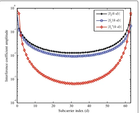
To compare with the original scheme, the desired signal of the proposed scheme is assumed to transmit on subcar-rier “0” (the edge of one subband). The difference between the original |Si(k−d)| and the proposed |Si(k−d)| is presented in Fig. 3, which is on a logarithm scale withk=
0 andN =64. InAi1andAi3, (a)|Si(k−d)|<|Si(k−d)| for most of thedvalues and (b) the total number of inter-ference signals is reduced to half because we include only even terms in the summation in Eqs. (11) and (12). Con-sequently, the interference signals in Eq. (15) are much smaller than those in Eq. (8) owing to reductions in both the number of interference signals and the amplitudes of the interference coefficients.
An interference cancelation demodulation scheme, cor-responding with the modulation strategy, is used to fur-ther reduce the interference. In the modulation process, each signal on thek+1th subcarrier (kdenotes an even number) is multiplied by−1 and summed with that on the
kth subcarrier. Thus, in the demodulation, the desired sig-nal inAi1orAi3is determined by the difference between Yi(k)andYi(k+1), and it can be derived as
Fig. 3A comparison among|Si(k−d)|,|Si(k−d)|and
|Si(k−d)|. This figure shows a comparison among three
interference coefficients for the proposed scheme
Yi,Ai1(k)=Yi,Ai1(k)−Yi,Ai1(k+1)
=
d∈Ai1 d=even
Xi(d)[−Ci(k−(d+1))Fi(d+1)
+Ci(k−d) (Fi(d)+Fi(d+1)) −Ci(k−(d−1))Fi(d)]+Ei,Ai1(k)
−Ei,Ai1(k+1) (16)
Yi,Ai3(k)=Y
i,Ai3(k)−Y
i,Ai3(k+1)
=
d∈Ai3 d=even
Xi(d)[−Ci(k−(d+1))Fi(d+1)
+Ci(k−d) (Fi(d)+Fi(d+1)) −Ci(k−(d−1))Fi(d)]+Ei,Ai3(k)
−Ei,Ai3(k+1) (17)
In addition, the signal inAi2, which does not include the
interference cancelation carriers, is the same as in Eq. (14), that is,
Yi,Ai2(k)=
d∈Ai2
Xi(d)Ci(k−d)Fi(d)+Ei,Ai2(k) (18)
Eventually, the estimated signal in the ith subband is denoted as
Yi(k)=Yi,Ai1(k)+Y
i,Ai2(k)+Y
i,Ai3(k) (19) Therefore, the whole estimated signal can be repre-sented as
Y(k)= M
i=1
Yi(k) (20)
Following the above analysis, the corresponding inter-ference coefficient of the estimated signal is denoted as
Si(k−d) = −Ci(k−(d+1))Fi(d+1) +Ci(k−d) (Fi(d)+Fi(d+1)) −Ci(k−(d−1))Fi(d) (21) The amplitude of|Si(k−d)|and its comparison with both |Si(k−d)| and|Si(k−d)|are shown in Fig. 3. In this figure, we can observe that |Si(k−d)| is smaller than|Si(k−d)|and that|Si(k−d)|is even smaller than |Si(k−d)| for the majority of d. This result indicates that the proposed demodulation scheme further reduces the interference to estimate signals whose range is inAi1
orAi3.
S(k−d)=
Si(k−d) d∈Ai1,Ai3
Si(k−d) d∈Ai2 (22)
We obtain the desired signal power on thekth subcar-rier according to Eqs. (16–18) and (22),
E|R(k)|2 = E|Xi(k)S(0)|2
= E|Xi(k)|2
|S(0)|2 (23) Meanwhile, the average power of the interference signal is calculated under the assumption that the transmit-ted data Xi(k) have a mean of zero and are statistically independent. The average power can be represented as
E|I(k)|2 =E
Thus, the expression of CIR for subcarrier k can be derived as
From Eq. (25), the CIR expression for the proposed scheme, where the desired signal is on subcarrier “0,” is derived as
and the CIR expression of the conventional UFMC system can be represented as
Equation (27) has the same assumption as that of Eq. (26), that is, the desired signal is on subcarrier “0”. However, to analyze the effect of the filter in the subband,
we place the desired signal in the middle subband. Then, Eq. (27) becomes
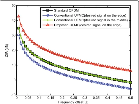
Based on Eqs. (26–28), the CIR curves of these three sit-uations are shown in Fig. 4, which also includes the CIR of a standard OFDM system. In this figure, the conven-tional UFMC systems, whose desired signal is on the edge of the subband, have a greater than 4-dB CIR reduction compared with the standard OFDM systems due to the influence of the filter. If the desired signal is in the mid-dle subband of the conventional UFMC system, its CIR is almost the same as that of standard OFDM systems. Therefore, the interference of the filter on these signal is negligible. By contrast, the proposed scheme improves more than 12 dB compared with conventional UFMC sys-tems in the range 0< ε≤0.5, and our scheme improves 8 dB compared with the standard OFDM systems.
This analysis shows that the proposed scheme restrains the interference of the filters and improves the system per-formance at the receiver. Moreover, the signal-to-noise ratio of the system is enhanced because the coherent addi-tion doubles signal level while increasing the noise level by a factor of only√2 due to noncoherent addition.
On the other hand, the actual spectral efficiency of the proposed scheme is reduced by the utilization of the rep-etition coding method. Therefore, we define (a)α as the ratio of the subcarrier amount in the middle subband to that in the whole subband and (b)β as the spectral effi-ciency to compare with that of standard OFDM systems. It is obvious thatα≤ 1. Then,βof the proposed scheme is obtained asα+(1−α)12(b/s/Hz), and it is smaller than
1 (b/s/Hz) of the standard OFDM system. To meet the required spectral efficiency, a larger signal alphabet size can be used to increase the band utilization. For example, combining QPSK modulation with the proposed scheme increasesβto [ 1+α] (b/s/Hz). The spectral efficiencyβ is also affected by the coefficientα, which is determined by the amount of edge subcarriers. This amount is related to both the type and the detailed parameters of the filter. Moreover, no complex coding methods are required for our proposed scheme, so it is easy to implement but just slightly increases the system complexity.
4 Simulation results
Here, we present four simulation experiments and their corresponding numerical results to verify the perfor-mance of the proposed scheme for UFMC systems. The experiments include (a) the uncoded BER performance evaluation under the conditions of different ratiosα, (b) the effect of CFO on BER performance, (c) the influence of the number of AEs on system performance, and (d) the mean square error (MSE) simulation for the CFO estima-tion. To validate the proposed UFMC, the standard and GB OFDM systems, where the GB OFDM and the pro-posed UFMC have the same parameterβ, are introduced and compared. Moreover, we define ε to represent the normalized CFO.
We introduce the raised cosine filter in the UFMC. Its roll-off factor is 1/2, which indicates that there are 1/4 car-riers on each edge of the subband affected by the filter. Moreover, we setα to be one of [1/2 3/4] to analyze the effect ofα on the system performance. According to the above definition of α, α=[1/2 3/4] means that there are [1/4 1/8] interference cancelation carriers inserted on the two edges, respectively. Additionally, an interference can-celation carrier value from 1/4 to 1/8 indicates that the interference is enhanced. Furthermore, we setεas one of [0.02 0.04 0.06 0.08 0.1].
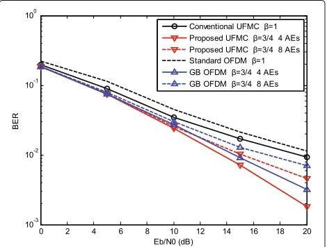
Experiment (a) is performed on four AEs, with different
εvalues used to represent different access conditions. Two AEs are the primary users whoseεvalues are equal to 0.1, and theεvalues for the other two AEs are 0.08. The simu-lation results are shown in Fig. 5, which presents the BER performance of the proposed system with differentα.
As shown in this figure, the standard OFDM system has the worst performance due to the high ISBI. Further-more, the proposed scheme for UFMC outperforms that of the GB OFDM under the condition of the same β. For instance, the performance of the proposed scheme is nearly twice as good as that of GB OFDM when Eb/N0 is 20 dB andαis 1/2, and the correspondingβ is 3/4. This result is the same as that of α = 3/4(β = 7/8). More-over,αalso influences the BER performance of the system. For example, whenα is changed from 1/2 to 1, the pro-posed UFMC becomes the conventional UFMC, and its
Fig. 5BER performance comparison with different ratio factorα. This figure illustrates the BER performance of the proposed UFMC with different ratio factor and compared with the other systems
BER increases from 10−3to 10−2when Eb/N0 is 20 dB.
By contrast, the performance is improved asαdecreases, especially for higher Eb/N0 (> 10 dB). Note that a small
α indicates a reduction in spectral efficiency. Thus, the selection ofαis important for the proposed scheme. Gen-erally, we should compromise between BER and spectral efficiency in practical applications.
The second experiment is implemented to analyze the effect of CFO on the proposed scheme and to compare the results with those of the other systems, in which we use the same CFO value for all AEs because of the poor ability of the OFDM to suppress ISBI. The simulation results are shown in Fig. 6.
The proposed UFMC has the best performance, the GB OFDM has the second best performance, and the worst performance is that of the standard OFDM. The com-parison of the proposed UFMC and the GB OFDM is performed with the same parameterβ. In addition, the BER performance degrades as the CFO in these systems increases because of the enhancement of ICI. Due to the ISBI, both the standard OFDM and the GB OFDM show a substantial reduction in BER in the region ofε < 0.6. Additionally, the proposed scheme demonstrates supe-rior performance compared with that of the conventional UFMC forαequal to 1/2 or 3/4. However, the interference of the filter degrades the BER performance asαincreases. The effect of the number of AEs on BER performance is analyzed in experiment (c), and the corresponding results are presented in Fig. 7. The parameters are the same as those of experiment (a). The figure shows that the pro-posed scheme has better performance than that of the GB OFDM for the same β and number of AEs, and it also outperforms the conventional UFMC system under con-ditions of differentα and number of AEs. These results are demonstrated by the BER value presented in the figure when Eb/N0 is 20 dB. The proposed scheme improves 7 and 2.5 dB compared with conventional UFMC and GB OFDM, respectively, under the condition of four AEs. For eight AEs, the improvements are 3 and 1.8 dB. Addition-ally, the proposed scheme outperforms the others even when the number of AEs is increased, although the BER performance degrades under these conditions.
We analyze the MSE performance by increasing Eb/N0 in the final experiment. Here, the pilot signal is inserted in the middle subband for both the proposed UFMC
Fig. 7BER performance evaluation of different number of AE for the proposed UFMC. This figure illustrates the effect of the different number of AE on BER performance and compared with the other systems
and GB OFDM. The corresponding results are shown in Fig. 8. The proposed UFMC outperforms the other sys-tems; however, the result of the conventional UFMC is similar to that of the proposed UFMC when Eb/N0 is less than 5 dB because of the high noise power. In conclusion, the proposed UFMC provides better performance than those of the three other systems.
5 Conclusions
In this paper, we proposed an interference cancelation scheme to mitigate the effects of both the filter and CFO by introducing an ICI self-cancelation scheme into the UFMC system to flexibly allocate the bandwidth in terms of the different requirements for 5G networks. To reduce the interference, our main focus is on the internal inter-ference of the filter. Each subband was regarded as a protected object, and the interference cancelation sub-carriers were inserted in pairs on the two edges. This proposed method avoids the significant reduction in spec-tral efficiency in the current system. In addition, the filter interference was reduced to further improve the sys-tem performance. The corresponding simulation results showed that the proposed scheme had better performance than that of the conventional UFMC because the filter interference on the edges was effectively suppressed.
We also compared the proposed scheme with the standard and GB OFDM systems. The simulation results showed that the standard OFDM system had the worst performance because of the serious ISBI, while the proposed UFMC outperformed the GB OFDM under the condition of the same spectral efficiency.
Acknowledgements
This work is supported in part by the National High Technology Research and Development Program (863 Program) of China under Grant 2015AA016901 and in part by the National Natural Science Foundation of China under Grant 61531007. The authors would like to thank the editor and anonymous reviewers for their constructive comments, which helped us to improve the manuscript.
Authors’ contributions
CL conceived and designed the study and then performed the experiments and wrote the paper. YJ reviewed and edited the manuscript. Both authors read and approved the final manuscript.
Competing interests
The authors declare that they have no competing interests.
Publisher’s Note
Springer Nature remains neutral with regard to jurisdictional claims in published maps and institutional affiliations.
Author details
1School of Electronic and Engineering, Beijing University of Posts and
Telecommunications, 100876 Beijing, China.2Beijing Key Laboratory of Work Safety Intelligent Monitoring, 100876 Beijing, China.3College of Electronic
Information Engineering, Hebei University, 071002 Baoding, China.
Received: 14 June 2017 Accepted: 17 December 2017
References
1. G Wunder,et al, 5GNOW: non-orthogonal, asynchronous waveforms for future mobile applications. IEEE Commun. Mag.52(2), 97–105 (2014) 2. G Fettweis, S Alamouti, 5G: personal mobile internet beyond what cellular
did to telephony. IEEE Commun. Mag.52(2), 140–145 (2014) 3. JG Andrews,et al, What will 5G be?. IEEE J. Sel. Areas Commun.32(6),
1065–1082 (2014)
4. GP Fettweis, The tactile internet: applications and challenges. IEEE Veh. Technol. Mag.9(1), 64–70 (2014)
5. E Hossain, D Niyato, Z Han,Dynamic Spectrum Access and Management in Cognitive Radio Networks. (Cambridge university press, Cambridge, 2009) 6. G Fettweis, M Krondorf, S Bittner, inProc. IEEE Veh. Technol. Conf.
GFDM—Generalized Frequency Division Multiplexing (IEEE, Barcelona, 2009), pp. 1–4
7. R Datta, D Panaitopol, G Fettweis, inProc. IEEE Int. Symp. Commun. Inf. Technol. (ISCIT). Analysis of cyclostationary GFDM signal properties in flexible cognitive radio (IEEE, Gold Coast, 2012), pp. 663–667 8. MG Bellanger, inProc. IEEE Int. Conf. Acoustics, Speech, and Signal
Processing. Specification and design of a prototype filter for filter bank based multicarrier transmission (IEEE, Salt Lake City, 2001), pp. 2417–2420 9. P Siohan, C Siclet, N Lacaille, Analysis and design of OFDM/OQAM
systems based on filterbank theory. IEEE Trans. Signal Process.50(5), 1170–1183 (2002)
10. B Farhang-Boroujeny, OFDM versus filter bank multicarrier. IEEE Signal Process. Mag.28(3), 92–112 (2011)
11. F Schaich, T Wild, Y Chen, inProc. IEEE Veh. Technol. Conf. Waveform contenders for 5G—suitability for short packet and low latency transmissions (IEEE, Seoul, 2014), pp. 1–5
12. F Schaich, T Wild, inProc. 6th Int. Symp. Commun. Control Signal Process. (ISCCSP). Waveform contenders for 5G-OFDM vs. FBMC vs. UFMC (IEEE, Athens, 2014), pp. 457–460
13. V Vakilian, T Wild, F Schaich, S ten Brink, JF Frigon, inProc. IEEE GLOBECOM Broadband Wireless Access Workshop. Universal-filtered multi-carrier technique for wireless systems beyond lte (IEEE, Atlanta, 2013), pp. 223–228
14. F Schaich, T Wild, inProc. 11th Int. Symp. Wireless Commun. Syst. (ISWCS). Relaxed synchronization support of universal filtered multi-carrier including autonomous timing advance (IEEE, Barcelona, 2014), pp. 203–208
15. A Ijaz,et al, Enabling massive IoT in 5G and beyond systems: PHY radio frame design considerations. IEEE Access.4, 3322–3339 (2017) 16. P Guan,et al, 5G field trials—OFDM-based waveforms and mixed
numerologies. IEEE J. Sel. Areas Commun.35(6), 1234–1243 (2017) 17. X Wang, T Wild, F Schaich, inProc. IEEE Veh. Technol. Conf. (VTC Spring).
Filter optimization for carrier-frequency- and timing-offset in universal filtered multi-carrier systems (IEEE, Glasgow, 2015), pp. 1–6
18. X Wang, T Wild,et al, inProc. European Wireless Conf. Universal filtered multi-carrier with leakage-based filter optimization (VDE, Barcelona, 2014), pp. 1–5
19. Y Zhao, SG Haggman, Intercarrier interference self-cancellation scheme for OFDM mobile communication systems. IEEE Commun. Lett.49(7), 1185–1191 (2001)
20. M Mukherjee, L Shu, V Kumar, P Kumar, R Matam, inProc. Int. Wireless Commun. and Mobile Computing Conf. (IWCMC). Reduced out-of-band radiation-based filter optimization for UFMC systems in 5G (IEEE, Dubrovnik, 2015), pp. 1150–1155
21. H Wang, Z Zhang, Y Zhang, C Wang, inProc. Int. Conf. on Wireless Commun. Signal Processing (WCSP). Universal filtered multi-carrier transmission with active interference cancellation (IEEE, Nanjing, 2015), pp. 1–6
22. L Zhang, P Xiao, A Quddus, Cyclic prefix-based universal filtered multicarrier system and performance analysis. IEEE Signal Process. Lett.
23(9), 1197–1201 (2016)
23. L Zhang, A Ijaz,et al, Subband filtered multi-carrier systems for multi-service wireless communications. IEEE Trans. Wireless Commun.
16(3), 1893–1907 (2017)
24. H Kim, J Bang, S Choi, D Hong, inProc. IEEE Wireless Commun. and Networking Conf. Resource block management for uplink UFMC systems (IEEE, Doha, 2016), pp. 1–4
25. B Smida, Coding to reduce the interference to carrier ratio of OFDM signals. EURASIP J. Wirel. Commun. Netw.2017(1), 1–11 (2017) 26. YH Peng,et al, Performance analysis of a new ICI-self-cancellation-scheme
in OFDM systems. IEEE Trans. Consum. Electron.53(4), 1333–1338 (2007) 27. PH Moose, A technique for orthogonal frequency division multiplexing