20th International Conference on Structural Mechanics in Reactor Technology (SMiRT 20) Espoo, Finland, August 9-14, 2009 SMiRT 20-Division 5, Paper 1592
Frequency-Dependent Impedances in the Time-Domain SSI Analysis:
Modification of Seismic Input
Alexander Tyapin
Dynamics and Seismic Safety Department, ”Atomenergoproject”, Moscow, Russia, e-mail: [email protected]
Keywords: Soil-Structure Interaction, Impedances, Frequency Domain, Soil Springs and Dashpots, Platform Model of the Soil-Structure System, Seismic Response Analysis.
1
ABSTRACT
The time-domain SSI analysis in engineering practice is usually performed using “platform model”: the model of the structure is placed on the distributed springs and dashpots resting on a rigid platform. Seismic input corresponding to the “kinematical interaction” is put on the platform.
The problem, however, is that spring and dashpot in the frequency domain can provide only a constant real part and a linear imaginary part of the dynamic stiffness, so the integral “platform impedances” cannot follow the “true impedances” in the frequency domain (rather sophisticated for the layered soil sites).
The author suggests the accounting for the frequency dependence of the “true impedances” in the time domain by means of the modification of the seismic input on the platform. The criterion for this modification is to provide the same structural response with “platform” impedances as for the “true” frequency-dependent impedances in the limit case of a rigid basement slab.
2
INTRODUCTION
Several years ago the author noted a certain gap between the SSI specialists and civil engineers (see Tyapin, 2007a). The SSI specialists perform the SSI analysis in the frequency domain using software of the SASSI type (Lysmer et al, 1981). The problem is that their structural models usually are not detailed enough (sometimes even stick models are used), thus requiring at least one more structural modeling from civil engineers. The reason is that the main part of analytical resources in the SSI analysis is used to model soil.
Civil engineers perform the SSI analysis in the time domain using the so-called “platform model”: the detailed model of the structure is placed on the distributed springs and dashpots resting on a rigid platform. Seismic input corresponding to the “kinematical interaction” is put on the platform (this input means the motion of rigid weightless basement without upper structure due to the seismic wave in the soil).
The problem with “platform model”, however, is that spring and dashpot in the frequency domain provide only a constant real part and a linear imaginary part of the complex dynamic stiffness, so the integral “platform impedances” cannot follow the “true impedances” in the frequency domain (rather sophisticated, especially for the layered soil sites). The obvious way out – to use more sophisticated springs and dashpots, additional masses, etc. – proved to be inconvenient and is not used in practice.
In practice the analytical results obtained by both groups of specialists for the same structures as a rule proved to be significantly different. Each group claimed the opponents to have too simplified models (of the soil or of the structure).
3
COMBINED ASYMPTOTIC METHOD
3.1 General approach
Let us call the response obtained in the frequency domain the “true” response. Then the goal can be reformulated as follows: we must reproduce somehow in the platform model the “true” dynamic loads acting from the soil to the moving basement. To be precise we are to reproduce the dynamic load field around the contact surface. However, if the contact surface is rigid, then only six integral dynamic forces are to be reproduced.
Dynamic loads acting from the soil to the contact surface are usually composed of two parts (assuming the linear soil properties and full contact). The first part is the load field acting to the immovable contact surface due to the seismic wave in the soil. The second part is the load field acting to the same contact surface as a response of the soil to the motion of that surface. No seismic waves are present in the soil in this second typical “contact problem”.
Many specialists including the author were trying to reproduce these two parts one by one, separately from each other. The first part of the load in fact can be reproduced in the platform model if the kinematical excitation in the platform model is replaced by the dynamic loads. But the second part requires modeling of the complex frequency-dependent impedances by means of springs and dashpots. Some attempts of this kind (using the so called “high order” supporting units) were successful (Tyapin, 2007b) but on the whole this approach is too sophisticated to be used in practice.
The new idea is to give up the attempts to model two parts of the dynamic loads separately. Let us try to reproduce the total load from the soil to the basement assuming the contact surface moves in a “true” way. Another new idea is to leave “platform” springs and dashpots whatever they are and to operate with platform kinematical excitation only. Generally speaking, six excitation components are enough to reproduce six integral forces for a rigid basement.
In other words the author suggests the accounting for the frequency dependence of the “true” impedances in the time domain by means of the modification of the seismic input on the platform. The criterion for this modification is to provide the same structural response with “platform” impedances as for the “true” frequency-dependent impedances in the limit case of a rigid base mat.
3.2 Mathematical modelling
The first stage of the proposed approach is to get the “true” response of the mat in the frequency domain. The upper structure on a rigid contact surface is represented by the “dynamic inertia” matrix linking the integral forces (acting on the contact surface from the upper structure) to the accelerations of this surface. This 6x6 frequency-dependent complex matrix is obtained using the information about the structural inertia and about the natural frequencies/modes of the structure resting on the fixed contact surface. As in the time domain the Rayleigh damping is usually used, the “dynamic inertia” matrix can be obtained as follows:
}
)
)(
(
){
/
1
(
)
(
2 2 2 2 11 0 j T j j j n j
S
S
i
i
i
M
i
M
! =+
+
!
!
+
!
=
%
#
"
#
%#
#
#
%#
#$#
#
(1)Here M0 is the traditional real inertia matrix 6 x 6; and are the Rayleigh damping coefficients for the upper structure; i is imaginary unit; j is natural frequency of j-th mode for the upper structure resting on the fixed contact surface; Sj is a line 1 х 6 of the participation factors for the j–th mode (the inertial normalization of the natural forms is assumed). One can note singularity in (1) at the zero frequency due to . This singularity will later disappear because the “dynamic inertia” matrix will be always multiplied by 2
.
The “true impedances” C and “kinematical interaction” transfer functions B are obtained in the frequency domain (e.g., by SASSI). The rigidity of the contact surface enables to combine the “dynamic inertia” and “true impedances” in the format of the 6x6 matrices. The “true” response U of the rigid contact surface is derived from the free field motion U0 as follows:
0 1 2 ) ( ) ( )] ( ) (
[C M C B U
The second stage is to get the “platform” transfer functions from the 6D movement of the platform to the rigid slab response. This time the “platform” impedances D() (derived from “soil” springs and dashpots distributed across the nodes on the base mat ) are used instead of the “true” ones. “Platform” impedances are combined with the same “dynamic inertia” matrix of a structure M() , as previously used. “Platform” response V is derived from the “platform” excitation V0 using almost the same formula as (2):
0 1 2 ) ( )] ( ) (
[D M D V
V =
!
"!
!
"!
(3)Our criterion is to get the “platform” response similar to the “true” one. Setting U and V equal we obtain the formula for the “platform” excitation
0 1
2 2
1
0 D( ) [D( ) M( )][C( ) M( )] C( )B( )U
V =
!
"!
"!
!
!
"!
!
"!
!
(4)Formula (4) means that the “platform” excitation is linked to the “kinematical” excitation through the certain modification matrix T()
0 0 1 2 2 1 ) ( ) ( ); ( )] ( ) ( )][ ( ) ( [ ) ( )
( D D M C M C V T B U
T
!
=!
"!
"!
!
!
"!
!
"!
=!
!
(5)The alternative form for the modification matrix is
) ( )] ( ) ( )][ ( ) ( [ ) ( )
(
!
E D!
1 D!
C!
C!
!
2M!
1!
2M!
T = + " " " " (6)
Here E is unit matrix 6 x 6.
Formula (6) means that the modification of the kinematical excitation before putting it on the platform can be treated as the addition of a certain excitation, proportional to the difference between “platform” and “true” impedances. This additional excitation is also proportional to the second degree of the frequency. It means that if we set “platform” impedances equal to the “true” ones at a certain frequency * then the additional excitation will be zero both at this special frequency and at zero frequency.
In the limit case of the weightless structure no additional excitation appears according to (6). In fact, in the platform model the response of the slab for the weightless structure is equal to the platform excitation; excitation without additional terms is just a “kinematical excitation”, so the response will be equal to the “kinematical excitation”. But “kinematical excitation” by definition is the response of the weightless rigid foundation – so (6) in this case gives us the true answer.
In practice the modification of the excitation is performed using direct and inverse FFT.
Modified excitation will provide the “true” response of the rigid basement in the platform model in the time-domain analyses. As a consequence the total response of the upper structure will also be “true”.
For the surface basement the initial three-component accelerogram of the seismic excitation after the modification turns into the six-component one. For the embedded basement the “kinematical” excitation has already six components, so the modification will not make technical difference for the platform time-domain analysis.
3.3 Advantages of the new approach
The author should like to point at several advantages of the proposed approach.
3.3.2. The proposed approach enables to get true angular forces without negative rotational damping. With damping there is a situation somewhat like the situation described above: after distributing integral translational damping around the slab civil engineers get some integral rotational damping. To match the “target” integral damping they have to add some distributed rotational dashpots. The difference with springs, however, is that the additional rotational damping often must be negative. Even if the software used allows setting up negative damping, such dashpots spoil the internal forces’ distribution even more.
3.3.3. The proposed approach enables to account for the frequency dependence of impedances and kinematical excitation. In two previous points the problem was to reproduce six integral impedances. Even if this is achieved for a certain frequency, another question is whether for the other frequencies the “platform” impedances will also reproduce the “true” ones. The answer is negative (even for the basements on the surface of a homogeneous halfspace the well-known formulae are approximate). The proposed approach enables to compensate the inevitable “error” arising in the “platform” impedances by the additional excitation.
3.3.4. The proposed approach enables to vary the soil stiffness easily. The modern safety codes require varying the soil stiffness in order to account for the possible deviations in the soil properties. All the soil modules of the “base case variant” are to be simultaneously multiplied or divided by the same coefficient. The obvious way to meet these requirements is just to repeat all the analysis with new soil data. However, the author derived, that for the soil modules increased a2 times the “scaled” impedances and “kinematical excitation” may be expressed through the “initial” ones as follows:
) / ( ) ( 0 2
1 a C a
C
!
=!
(7)) / ( )
( 0
1 B a
B
!
=!
(8)Thus, scaling the frequencies one can substitute (7, 8) into (2) and get
= ! = ! ) ( ) ( ) ( )] ( ) ( [ )
( 1 2 2 1 1 1 0
1 a
"
C a"
a"
M a"
C a"
B a"
U a"
U ) ( ) ( ) ( )] ( ) ( [ ) ( ) ( ) ( )] ( ) (
[ 0 0 0
1 2 0 0 0 0 2 1 2 2 0 2 ! ! ! ! ! ! ! ! ! ! !
! a M a a C B U a C M a C B U a
C
a " " = " "
= (9)
Comparing (9) to (2) one can see the only term to be recalculated in (2): this is M(a ). All the rest will stay in place. As a result, the impedances and “kinematical excitation” obtained at certain frequencies for the base case variant may be used for the “scaled” variants at “scaled” frequencies.
3.3.5. The proposed approach clarifies the roles of the SSI specialists and civil engineers in the analytical process. Information needed to obtain the dynamic inertia matrix is the responsibility of civil engineers. The format of this information is convenient for the general purpose FEM software. The SSI specialists no longer need to model the upper structure. Their responsibility is “true” impedances and “kinematical excitation” for a rigid basement. No resources are wasted to model the upper structure, so the underground part may be modeled in details. The SSI specialists may give civil engineers the recommendations about “platform” impedances (e.g., six “true” impedances at a certain frequency). After that the modification of the seismic input is performed using simple and cost-effective procedures described above. Further “platform” analysis is the responsibility of civil engineers. After the “platform” response of the rigid basement to the modified excitation is checked to follow the “true” response, the artificial rigidity of the base mat can be released, and final platform analysis is performed by civil engineers in the traditional way, though with different excitation. As usually the basements of the main NPP buildings are comparatively stiff, the influence of the basement flexibility is not going to be extremely significant.
3.3.6. The proposed approach provides a powerful tool to verify the “platform” model of the soil-structure system against compact and transparent benchmark calculations. As modern FEM structural models have hundreds thousand of nodes, they are practically not transparent. As a result, there is a space for different errors and a need to have compact and transparent benchmark tests to verify the sophisticated models at least partly. In fact, during the implementation of the proposed approach in the analytical practice it turned out that the response of the rigid slab in the “platform” model does not always follow the “true” response. This fact encouraged the author to develop special procedure for the verification of the platform model of the soil-structure system. The procedure consists of several benchmark calculations verifying certain parts of the model.
tested against the result of (3) calculated for the traditional inertia. This test verifies integral “platform” impedances and the absence of erroneous fixations in the platform model.
Benchmark B. Natural frequencies of the platform model are tested against matrix Re[D( )- 2M() ]. This test verifies the “dynamic inertia” calculations.
Benchmark C. Kinematical excitation is put to the platform for the flexible upper structure with rigid basement slab. The response is tested against the results of (3). In fact, the internal damping in the upper structure is verified here (after previous benchmarks did well).
Benchmark D. Modified excitation is put to the platform and the response of the rigid base mat is tested against the “true” response obtained in the frequency domain.
3.4 Further development of the new approach
The only limitation for the new approach is the rigidity of the contact surface. As a consequence, though the integral loads from the soil in the platform model with modified excitation will be “true”, the internal forces’ distribution in the base mat will depend on the actual spring/dashpot distribution around the base mat in the platform model. On the other hand, the spring/dashpot distribution is not so far covered by the proposed approach. The author further plans to develop some recommendations about the choice of spring/dashpot distribution. The goal is to get the internal forces’ distribution close to the “true” one.
4
SAMPLE ANALYSIS
The reactor building of the NPP was analyzed using the proposed approach. ABAQUS was used to build the platform model. SASSI was used to obtain “true” impedances and kinematical excitation (embedment and partial soil-structure separation were taken into account) for the soil foundation composed of 20 layers resting on the flexible halfspace. One of the horizontal “true” impedances and vertical one are shown on Fig.1.
Real parts of impedances
-1,0E+08 0,0E+00 1,0E+08 2,0E+08 3,0E+08 4,0E+08 5,0E+08 6,0E+08 7,0E+08 8,0E+08 9,0E+08
0 5 10 15 20 25
Frequency, Hz ReCx
ReCx(ASCE4-98)
ReCz
Imaginary parts of impedances
0,0E+00 2,0E+08 4,0E+08 6,0E+08 8,0E+08 1,0E+09 1,2E+09 1,4E+09 1,6E+09 1,8E+09
0 5 10 15 20 25
Frequency, Hz ImCx
ImCx(ASCE4-98)
ImCz
ImCz(ASCE4-98)
Figure 1. Real and imaginary parts of horizontal (a) and vertical (b) impedances
Simplified impedances following the ASCE4-98 recommendation are also shown for the comparison. Parameters of the halfspace were similar to the layer immediately under the base mat. The frequency 6 Hz was chosen to fix the translational impedances for the platform model. No rotational springs or dashpots were used in the platform model, so even at 6 Hz the “true” rotational impedances were not reproduced. There were 4710 nodes at the basement slab in the platform model. The translational impedances were distributed among these nodes according to the corresponding areas (as springs and dashpots).
Flexibility of the upper structure was described by 1084 natural frequencies/modes for the upper structure on the fixed basement slab. Natural frequencies ranged up to 50 Hz. Accumulated modal masses are shown on Fig.2. This form of presentation is convenient in case of great number of natural forms.
Accumulated modal masses
0,0E+00 2,0E+07 4,0E+07 6,0E+07 8,0E+07 1,0E+08 1,2E+08 1,4E+08 1,6E+08 1,8E+08 2,0E+08
0 2 4 6 8 10 12 14 16 18 20
Frequency, Hz
X
Y
Z
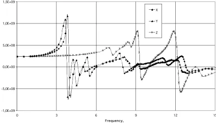
Real and imaginary parts of the complex translational “dynamic masses” are shown on Fig.3. Unlike the traditional masses the “dynamic masses” are complex (due to the damping in the upper structure) and different from each other (due to the flexibility of the upper structure).
a)
Real parts of dynamic masses
-1,0E+09 -5,0E+08 0,0E+00 5,0E+08 1,0E+09 1,5E+09
0 3 6 9 12 15
Frequency, Hz
X
Y
Z
b)
Imaginary parts of dynamic masses
-1,8E+09 -1,6E+09 -1,4E+09 -1,2E+09 -1,0E+09 -8,0E+08 -6,0E+08 -4,0E+08 -2,0E+08 0,0E+00
0 3 6 9 12 15
Frequency, Hz X
Y
Z
Figure 3. Translational “dynamic masses” in the frequency domain
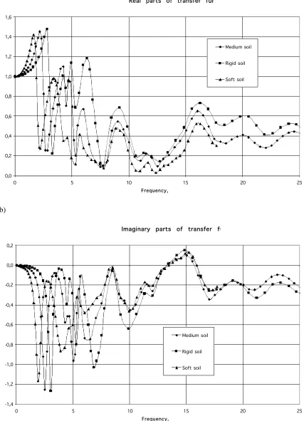
modulus). These are transfer functions from the motion of the soil surface in x-direction to the response in the same direction.
a)
Real parts of transfer functions
0,0 0,2 0,4 0,6 0,8 1,0 1,2 1,4 1,6
0 5 10 15 20 25
Frequency, Hz
Medium soil
Rigid soil
Soft soil
b)
Imaginary parts of transfer functions
-1,4 -1,2 -1,0 -0,8 -0,6 -0,4 -0,2 0,0 0,2
0 5 10 15 20 25
Frequency, Hz
Medium soil
Rigid soil
Soft soil
Figure 4. Transfer functions for the soil with different stiffness
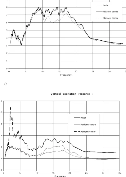
a)
Horizontal excitation response spectrum along Ox axis
0 1 2 3 4 5 6 7 8 9
0 5 10 15 20 25 30 35
Frequency, Hz
Initial
Platform centre
Platform corner
b)
Vertical excitation response spectra
0 2 4 6 8 10 12
0 5 10 15 20 25 30 35
Frequency, Hz
Initial
Platform centre
Platform corner
Figure 5. Response spectra of the initial and modified excitations
Horizontal accelerations in the centre and in the corner are almost the same: it means that very little torsion occurs. Besides, the “modified” horizontal acceleration is not so far from the initial one. The main difference is in the frequency range 12…16 Hz, where the imaginary part of the impedance deviates from the linear function (see Fig.1). Vertical acceleration in the centre looks alike, compared to the initial vertical excitation. However, vertical accelerations in the corner (i.e. under the corner of the basement) are substantially different from those in the centre. It means that the rocking components in the “modified” excitation are significant (neither rocking, nor torsion were in the initial excitation).
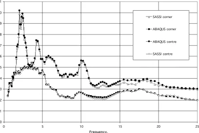
Fig.6 shows 5% vertical acceleration response spectra in the centre and in the corner of the base mat obtained by two analyses: in the frequency domain and in the time domain.
0 1 2 3 4 5 6 7 8 9 10 11
0 5 10 15 20 25
Frequency, Hz
SASSI corner
ABAQUS corner
ABAQUS centre
SASSI centre
Figure 6. Response spectra for the rigid basement slab in vertical direction
According to the theory, both analyses should give the same result. On the Fig.6 the results are very close but not the same (especially in the corner). The additional analyses clarified, that the difference appears only for the flexible upper structure. The author supposes that the reason is the inconsistent implementation of the Rayleigh damping in the ABAQUS model; damping was set element-wise; so, the lumped masses did not influence the damping matrix. As a result, all the difference is on the same side; the ABAQUS spectra are slightly higher than the SASSI ones.
Nevertheless, the author considers the sample to verify the proposed approach.
5
CONCLUSION
The proposed approach enables to get “true” movement of the rigid base mat in the time domain analysis with platform model, taking into account the frequency dependence of the impedances. This approach may be called “combined” as it combines initial calculations in the frequency domain (“true” impedances and the modification matrix) and calculations in the time domain (final dynamic analysis). The approach may be also called “asymptotic” as it is precise for the rigid base mats (excluding stresses in the mat itself). However, the main NPP buildings usually have comparatively stiff basements, so the error will be likely not so great.
REFERENCES
J.Lysmer et al. 1981. SASSI - A Computer System for Dynamic Soil-Structure Interaction Analysis. Report No. UCB IGT/81-02, University of California, Berkeley.
Tyapin A.G. 2007a. The frequency-dependent elements in the code SASSI: a bridge between civil engineers and the soil-structure interaction specialists. Nuclear Engineering and Design. Vol. 237. P 1300-1306.