Department of Electrical Engineering, Faculty of Engineering, South-East Asia University, Thailand
Article Info ABSTRACT
Article historys: Received Jun 1, 2019 Revised Sep 9, 2019 Accepted Nov 27, 2019
This paper proposes the artificial intelligence (AI)-based optimal PID controller design optimization of brushless direct current (BLDC) motor speed control with phase advance approach. The proposed control system allows the speed adjustment of the BLDC motor by phase advance technique. In this paper, two selected AI algorithms, i.e., the adaptive tabu search (ATS) and the intensified current search (ICS) are conducted as the optimizer for the PID controller design. The proposed control system is simulated by MATLAB/SIMULINK. Results obtained by the ATS and ICS will be compared with those obtained by the Ziegler-Nichols(ZN) tuning rule and the genetic algorithm (GA). It shows that the speed response of the BLDC motor by phase advance with the PID controller optimized by the ICS outperforms better than the ZN, GA and ATS.
Keywords:
Artificial Intelligence PID Controller BLDC Motor Phase Advance
Copyright © 2019 Institute of Advanced Engineering and Science. All rights reserved.
Corresponding Author: Manoon Boonpramuk,
Department of ElectricalEngineering,Faculty of Engineering, Pathumwan Institute ofTechnology, Bangkok, Thailand. Email: [email protected]
1. INTRODUCTION
The brushless direct current (BLDC) motor is a kind of synchronous motor having permanent magnets on the rotor and stator winding. It has been broadly utilized in automotive, hard disk, robotics, vehicle, aerospace, home appliance and instrumentation. The BLDC motor has many advantages over the induction motor including simple structure, low size, excellent efficiency, less maintenance, low noise and wide speed range [1] -[3].In the future, motor controllers need to be improved for application targets through simple and economical design.
The BLDC motor can be expanded to operation speed range more than base speed by phase advance [4]. This allows the utilization of BLDC motor in various applications for high speed range. So, it is necessary to have a controller that can improve performance for developing three phases of the BLDC motor drive. The PID controller is extensively used in the BLDC motor drive because of the effectiveness and simple structure [5], [6]. The parameters of PID controller are very essential for the performance of motor control system, particularly in motor device with nonlinearity and large inert [7]. From the previous researches [4], [8]-[11], the BLDC motor system with phase advance is regulated by conventional control methods. It is found that the performance of motor has steady state error and slow speed response. Therefore, the speed response of the BLDC motor system with phase advance can be done effectively by optimizing the values of PID controller parameter using artificial intelligence (AI) algorithms. Furthermore, the applications of AI algorithms for PID controller of the BLDC motor system with phase advance have not been presented in the previous researches [4], [8]-[11]. The AI algorithms have been extensively accepted for the controller design in many industrial applications [12]. For example, designing of BLDC rotor speed by fuzzy logic [13], genetic algorithm (GA) for controller design [14],self-turning the PID controller using GA [15], controller design using adaptive tabu search (ATS) [16], aircraft electric control by ATS [17] and control synthesis using current search (CS) [18],
[19].Hence, this paper presents the use of AI algorithms for tuning the PID parameters (KP, Ki and Kd) for controlling the BLDC motor with phase advance.
In this paper, there are divided six sections. Firstly, the introduction is described. Secondary, the details of the modeling of BLDC motor and phase advance technique are presented. Thirdly, the details of AI algorithms are demonstrated. Fourthly, the application of selected AI algorithms is tuned the PID parameters for the BLDC motor system. Fifthly, the simulation results are illustrated. Finally, the conclusions are described.
2. MODELING OF BLDC MOTOR AND PHASE ADVANCE TECHNIQUE
2.1. Modeling of BLDC motor
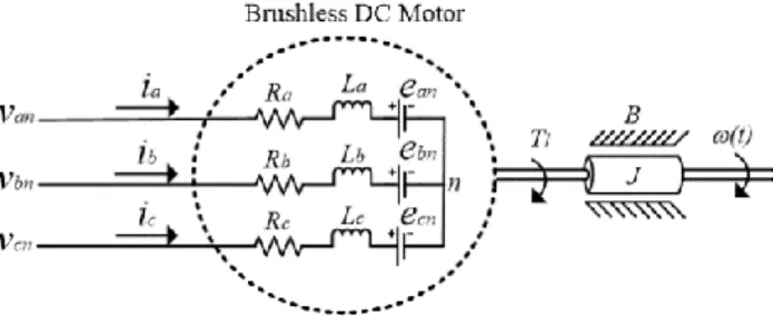
The equivalent circuit model of the BLDC motor is illustrated as shown in Figure 1.The modeling of BLDC motor can be performed in equation (1) [1], [2].
Figure 1. Equivalent circuit model
In Figure 1, it consists of inductance, backemf and resistance, where van, vbn and vcnare the output phase voltages, ia, ib and icrepresent the phase currents, La, Lb and Lcare the phase inductances, ean, ebn and ecn are phase back emfs, Ra, Rb and Rcare the phase resistances of rotor.
+ + = + + = + + = cn c c c c cn bn b b b b bn an a a a a an e dt di L i R v e dt di L i R v e dt di L i R v (1)
The trapezoidal back emfs in equation (2) are related to a function of rotor position, where eand Kw are the electrical rotor angleand the back emf constant of each phase,r denotes the motor angular velocity in rad/s and fa, fband fc represent the function of rotor position.
− = − = = ) 3 / 4 ( ) 3 / 2 ( ) ( e c r w cn e b r w bn e a r w an f K e f K e f K e (2)
The electromagnetic torque is a simple equation of phase current and phase back emf as expressed in equation (3), whereTeis electromagnetic torque and Tea, Teb and Tec represent phase electric torque.The relation between the speed and the torque are stated in equation (4), where Tlis an indicative of load torque in N.m, J denotes the moment of inertia in kg-m2 and B is the static friction in N.m-s/rad.
r c cn b bn a an ec eb ea e i e i e i e T T T T + + = + + = (3) l e B T dt d J T = + + (4) 2.2. Phase advanceThe phase advance technique is a common control of the phase current to lead the phase back emf. It can increase the speed of BLDC motor over the base speed. Figure 2 shows the phase currents shifted by the angle of advto phase back emf. The phase currents can be varied from 0o to 60o, electrical degree [8]-[10].
Figure 2. Waveforms of phase current and phase back emf
The phase advance is described in equation (5), where Ls is an indicative of phase inductance, adv is the angle of phase advance, Vdc is an indicative of voltage source, n is rotor speed and Iphdenotes the phase current. pn V I L r dc ph s r adv= , =2 (5)
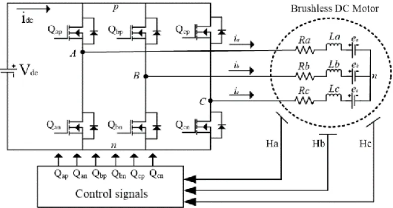
In Figure 3, it shows the three phase inverter for BLDC motor drive. In this work, the proposed drive system composes of three phase inverter, switch control signals, Hall effect sensors, BLDC motor and DC voltage source. The switching states of three phase inverter based on Hall effect signals are visualized in Figure 4.
Figure 3. Three phase inverter of BLDC motor drive
Table 1 shows the switching states for the BLDC motor drive. Each step has an interval of 60o ,electrical degree.
Table 1. Switching states
Figure 5 shows Hall effect signals which effect the switching states of three phase inverter. The phase advance adjusts the Hall effect signals (Ha*, Hb* and Hc*) leading the previousHall effect signals (Ha, Hb and Hc).
Figure 5. Waveforms of Hall effect signal 3. ARTIFICIAL INTELLIGENCE
Recently, AI algorithms have been broadly utilized to solve combinatorial and engineering problems. In this section, the AI algorithms consisting of the intensified current search (ICS) and the ATS are briefly reviewed.
3.1. ICS algorithm
The CS is one of the AI algorithms based on the current divider of the electric circuits and network systems [18], [19]. Theoretically, the CS only composed the memory list (ML). For solving the computational problems, the ICS algorithm has been modified version by adding the adaptive radius (AR) and the adaptive neighborhood (AN). In order to find the optimal solution, the ICS is able not only to escape the local entrapment but also to speed up the search process in the search space. The movement of the ICS over search space is illustrated in Figure 6. The pseudo code of the ICS is described in Figure 7 [20], [21].
Figure 6. Movement of the ICS algorithm [20], [21]
Step Interval Switch Phase A Phase B Phase C
1 0 - 60 Qap,Qbn + - 0 2 60 - 120 Qap,Qcn + 0 - 3 120 - 180 Qbp,Qcn 0 + - 4 180 - 240 Qbp,Qan - + 0 5 240 - 300 Qcp,Qan - 0 + 6 300 - 360 Qcp,Qbn 0 - +
Figure 7. Pseudo code of ICS [20], [21] 3.2. ATS algorithm
The ATS was firstly launched in 2002 [22], [23] as one of the AI algorithms. It has been modified version of the TS [24], [25] and based on an interactive neighborhood search approach for solving combinatorial and nonlinear problems. The mechanisms of ATS have the adaptive radius (AR) and back tracking (BT). To speed up the search process of ATS, AR mechanism is utilized to intensity. Moreover, the BT mechanism is able to conduct to escape the local entrapments. The movement of ATS over search space can be illustrated in Figure 8. The pseudo code of the ATS is shown in Figure 9 [22], [23].
Figure 8. Movement of the ATS algorithm [22], [23]
Figure 9. Pseudo code of ATS [22], [23]
4. PID CONTROLLER OF BLDC MOTOR
The PID controller was firstly conducted to industrial applications in 1939 [26]. It has been extensively used in the industrial control systems because of its simple structure and effectiveness. Figure 10 shows the conventional control loop of PID controller, where R(s) is reference input signal, E(s) is an error signal, U(s) is control signal, D(s) is disturbance signal and C(s) is output response, respectively. Gc(s) is the PID controller model and Gp(s) is the BLDC motor model. Referring to Figure 10, Gc(s) will receive E(s) different between R(s) and C(s)) and generate U(s) for controlling Gp(s) to provide desired C(s) according to R(s), whereas regulating D(s), simultaneously. The liner transfer function of the BLDC motor plant can be stated in equation (6) [27], where A is the driver time constant, KA is the driver gain and Ktis thetorque constant.
Figure 10. PID conventional control loop
( ) ( ) ( ) + + + + + = w t a a a a t A A P K K B R s B L J R s J L K s K s G 2 1 ) ( (6)
The PID controller model in the s-domain transfer function is stated in equation (7). Therefore, the PID controller can be written in the form of closed loop as shown in equation (8).
s K s K K s G d i P C( )= + + (7) ) ( ) ( 1 ) ( ) ( ) ( ) ( s G s K s K K s G s K s K K s R s C P d i P P d i P + + + + + = (8)
Figure 13, respectively.
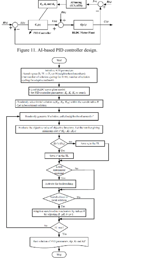
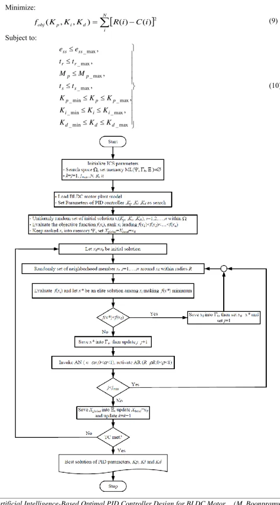
Figure 12. Flowchart of the ATS algorithm for PID controller design Minimize:
− = N i d i p obj K K K R i C i f ( , , ) ( ) ( )2 (9) Subject to: max _ min _ max _ min _ max _ min _ max _ max _ max _ max _ , , , , , , d d d i i i p p p s s p p r r ss ss K K K K K K K K K t t M M t t e e (10)Referring to Figure 11, the AI algorithms were simulated via MATLAB/ SIMULINK run on CPU Core i5, 2.5 GHz and 6 Gbytes DDR-RAM computer. The optimal gains using AI techniques are setup. The design optimization by the ATS and ICS are performed as shown in Table 2 and Table 3, respectively. In addition, results obtained from the ATS and ICS will be compared with Ziegler-Nichols (ZN) tuning rule [28],[29] and GA [30]. The ZN tuning rule is the analytical design method, while the GA is one of the most popular metahueristic optimization techniques. However, both ZN and GA are not new anymore. Then, details of ZN and GA are omitted in this paper. Readers can find their details from the given references. The parameters of the GA are shown in Table 4. For design the PID controller, the search spaces of PID parameters in equation (10) are specified in Table 5.
Table 2. Parameters of ATS
Table 3. Parameters of ICS
Table 4. Parameters of GA
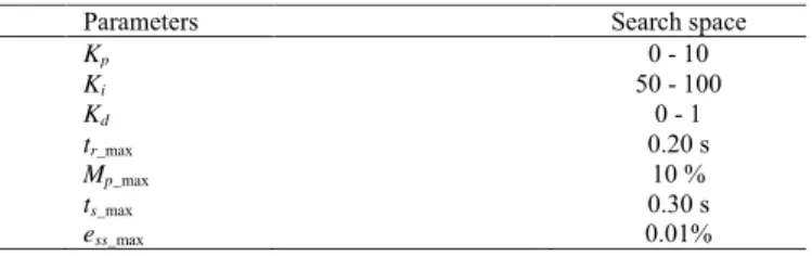
Table 5. The search spaces of PID parameters
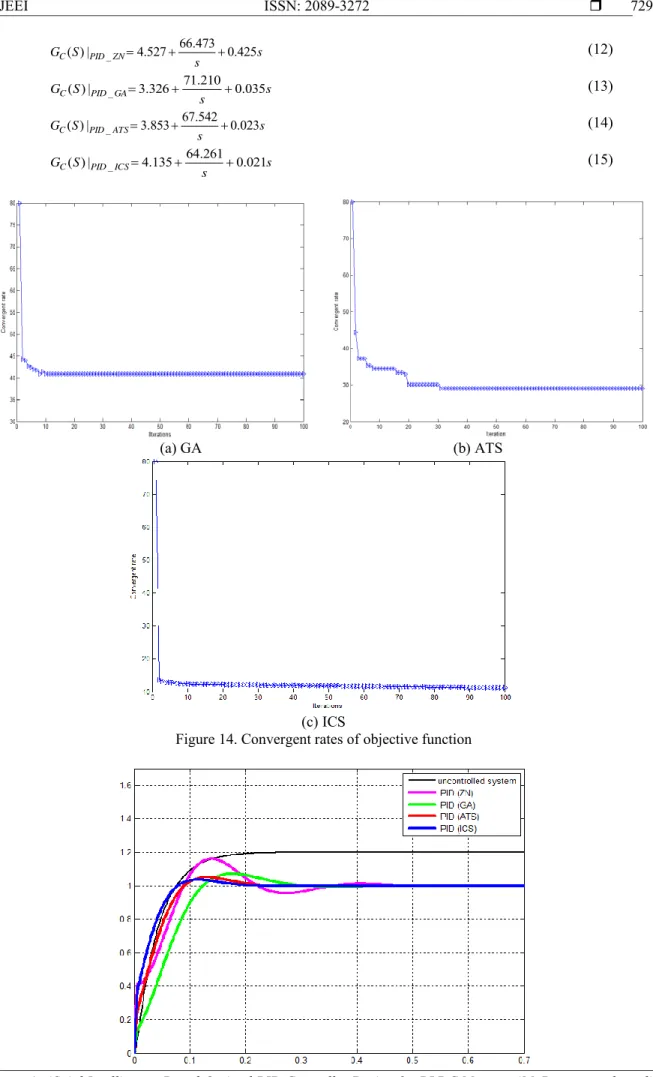
The convergent rates of the proposed objective function in equation (9) and its corresponding inequality constrained functions in equation (10) proceeded by GA, ATS and ICS are depicted in Figure 14. The PID parameters of the BLDC motor system obtained by ZN tuning rule and optimized by GA, ATS and ICS are expressed in (12), (13), (14) and (15), respectively. The system responses of the BLDC motor without controller and with PID controllers are plotted in Figure 15 and summarized in Table 6.
Parameters Values Number of iterations 100 Search radius 0.5 Number of neighborhood 10 Solution cycling 10 Back tracking 5
Adaptive radius: fobj < 0.5, fobj < 0.1, fobj < 0.01 0.25, 0.1, 0.01
Parameters Values
Number of iterations 100
Number of neighborhood 10
Number of search direction 10
Search radius 0.5
Solution cycling 10
Adaptive radius: fobj < 0.5, fobj < 0.1, fobj < 0.01 0.25, 0.1, 0.01
Adaptive neighborhood: fobj < 0.5, fobj < 0.1, fobj < 0.01 15, 20, 25
Parameters Values Number of iterations 100 Number of population 10 Crossover rate 95 % Mutation rate 5% Generation 100
Parameters Search space
Kp 0 - 10 Ki 50 - 100 Kd 0 - 1 tr_max 0.20 s Mp_max 10 % ts_max 0.30 s ess_max 0.01%
s s S GC PID ZN 0.425 473 . 66 527 . 4 | ) ( _ = + + (12) s s S GC PID GA 0.035 210 . 71 326 . 3 | ) ( _ = + + (13) s s S GC PID ATS 0.023 542 . 67 853 . 3 | ) ( _ = + + (14) s s S GC PID ICS 0.021 261 . 64 135 . 4 | ) ( _ = + + (15) (a) GA (b) ATS (c) ICS
the slowest response. The system response with the PID controller obtained by the ZN tuning rule provides faster response but greater overshoot than that by the GA. The system response with the PID controller optimized by the ATS performs faster response and smaller overshoot than that by the GA and ZN tuning rule. However, the system response with the PID controller optimized by the ICS outperforms that by ZN tuning rule, GA and ATS with the fastest response and smallest overshoot according to inequality constrained functions in equation (10).
In addition, the BLDC motor speed control system with phase advance technique and the PID controllers obtained by the ZN tuning rule and optimized by the GA, ATS and ICS is simulated by MATLAB/SIMULINK as depicted in Figure 16. The BLDC motor in the simulink block diagram is a three phase motor rated 3,000 rpm. The effectiveness of the obtained PID controllers is analyzed under different operating conditions and compared with the conventional control of phase advance. Figure 17(a) depicts the responses of BLDC motor when speed changed from 0 to 2,800 rpm with no load condition without phase advance. From the Figure 17(a), the responses of speed control are very satisfactory. Figure 17(b) shows the relation between the phase current (ia) and the back emf (ea). It was found that ia and ea are in phase.
Figure16. Simulink block diagram
Figure17. Responses of BLDC motor speed control system without phase advance (no load)
Figure 18(a) depicts the responses of BLDC motor speed control system when speed changed from 2,800 to 3,100 rpm with no loadcondition with phase advance. From the figure18(a), the BLDC motor system can extend the speed range over the 3,000 rpm. The speed response with the PID controller optimized by the ICS outperforms other controllers. Figure 18(b) depicts the relation between ia and ea, it was found that ia leads ea at 0.5 s.
(a) Step change from 2,800 to 3,100 rpm (b) Comparison between ia and ea Figure18. Responses of BLDC motor speed control system with phase advance (no load)
Figure 19 depicts the responses of BLDC motor speed control system when speed changed from 3,100 to 2,800 rpm at 0.5 s with no load in Figure 19(a) and with load of 2 N.m in Figure 19(b). From Figure 19, the speed response with the PID controller optimized by the ICS also provides better response than other controllers with the least settling time of both no load and load.
(a) No load (b) Load of 2 N.m
Figure19. Responses of BLDC motor speed control system with no load and on load of 2 N.m
(a) Step change from 3,100 to 3,400 rpm (b) Step change from 3,400 to 3,100 rpm Figure20. Responses of BLDC motor speed control system with phase advance at constant load of 2 N.m
controllers for load regulation purpose. For overall system performance, the PID controller optimized by the ICS for BLDC motor speed control system with phase advance outperforms other controllers.
Figure21. Responses of load regulation of BLDC speed control system 6. CONCLUSION
The AI-based optimal PID controller design optimization for BLDC motor speed control with phase advance has been presented in this paper. Two selected AI algorithms, i.e., the ATS and ICS, have been applied as the optimized to the PID controller design. In this paper, the mathematical model of the BLDC motor and the phase advance technique have been provided. Algorithms of the ATS and ICS have been clearly reviewed. The proposed design approach has been conducted by using MATLAB/SIMULINK. The PID controllers optimized by the ATS and ICS have been compared with the ZN tuning rule and the GA. As results, the ATS and ICS could successfully give optimal PID controllers. The simulation results shown that the responses of the BLDC motor speed control by phase advance with the PID controller designed by the ICS outperformthat obtained by the ZN, GA and ATS, respectively. Moreover, the proposed ICS algorithm for PID controller design can be improved the system response effectively.
REFERENCES
[1] J.R. Hengershot and T.J.E. Miller, Design of Brushless Permanent Magnet Motor, Oxford Science, 1994. [2] D.Hanselman, Brushless Permanent Magnet Motor Design, Magna Physics Publishing, 2006.
[3] S. Poonsawat and T. Kulworawanichpong, “Speed Regulation of a Small BLDC Motor using Genetic-Based Proportional Control,” World Academy of Science, Engineering and Technology, vol. 2, no. 5, pp. 203-208, 2008. [4] M. S. bin Mohd and M. N. bin Karsiti, “Phase Angle Adjustment for Phase Advance Control of Brushless DC Motor,”
International Conference on Intelligent and Advanced Systems (ICIAS), pp. 1-6, 2014.
[5] K. Ang, G. Chong, and Y. Li, “PID Control System Analysis, Design and Technology,” IEEE Transactions Control
System Technology, vol. 13, no. 4, pp. 559-576, 2005.
[6] A. S. Othman and A. Mashakbeh, “Proportional Integral and Derivative Control of Brushless DC Motor,” European
Journal of Scientific Research, vol. 35, no. 4, pp. 198-203, 2009.
[7] A. Sharma, H. Negi and D. Punetha, “Adaptive Speed Control of BLDC Motor with Effective Starting and Minimized Cost and Core Loss,” International Conference on Advances in Computing Communication and Automation,pp. 175-178, 2016.
[8] J. J. Moon, W. S. Im and J. M. Kim, “Novel Phase Advance Method of BLDC Motors for Wide Range Speed Operations,” Applied Power Electronics Conference and Exposition (APEC)-Eighth Annual IEEE, pp. 2343-2348, 2013.
[9] B. M. Nguyen and M. C. Ta, “Phase Advance Approach to Expand the Speed Range of Brushless DC Motor,”
International Conference on Power Electronics and Drive Systems, pp. 1255-1262, 2007.
[10] H. Kong, J. Liu and G. Cui, “Study on Field-Weakening Theory of Brushless DC Motor Based on Phase Advance Method,” International Conference on Measuring Technology and Mechatronics Automation, pp. 583-586, 2010. [11] S. I. Park, T. S. Kim, S. C. Ahn and D. S. Hyum, “An Improved Current Control Method for Torque Improvement
of High-Speed BLDC Motor,” Applied Power Electronics Conference and Exposition (APEC), pp. 294-299, 2003. [12] K. N. Sujatha, K. Vaisakh and G. Anand, “Artificial Intelligence Based Speed Control of Brushless DC Motor,” IEEE
International Conference PES General Meeting, pp. 1-6, 2010.
[13] J. Mostafapour, J. Reshadat and M. Farsadi, “Improved Rotor Speed Brushless DC Motor Using Fuzzy Controller,”
Indonesian Journal of Electrical Engineering and Informatics(IJEEI), vol. 3, no. 2, pp. 78-88, 2015.
[14] S. Mehrdad and C. Greg, “An Adaptive PID Controller Based on Genetic Algorithm Processor,” IEE Conference
Genetic Algorithm in Engineering System, pp. 88-93, 1995.
[15] Y. Mitsukura, T. Yamamoto and M. Kaneda, “A Design of Self-tuning PID Controller using a Genetic Algorithm,”
The American Control Conference, 1999, pp. 1361-1365.
[16] D. Puangdownreong and S. Sujitjorn, “Obtaining an Optimum PID Controllers via Adaptive Tabu Search,”
International Conference on Adaptive and Natural Computing Algorithm, pp. 747-755, 2007.
[17] S. Khalid, “Optimized Aircraft Electric Control System Based on Adaptive Tabu Search Algorithm and Fuzzy Logic Control,” Indonesian Journal of Electrical Engineering and Informatics(IJEEI), vol. 4, no. 3, pp 149-164, 2016. [18] A. Sakulin and D. Puangdownreong, “Control Synthesis for Unstable Systems via Current Search,” The WSEAS
International Conference on Artificial Intelligence, pp. 131-136, 2012.
[19] D. Puangdownreong and A. Sukulin, “Obtaining an Optimum PID Controllers for Unstable Systems using Current Search,” International Journal of Systems Engineering, Aplications & Development, vol. 6, no. 2, pp. 188-195, 2012. [20] A. Nawikavatan, S. Tunyasrirut and D. Puangdownreong, “Application of Intensified Current Search to Optimum
PID Controller Design in AVR System,” Asian Simulation Conference, pp. 255-266, 2014.
[21] D. Kumpanya, S. Thaiparnat and D. Puangdownreong, “Parameter Identification of BLDC Motor via Metaheuristic Optimization Techniques,” International Conference on Industrial Engineering and Service Science, pp. 322-327, 2015.
[22] D. Puangdownreong, K. Areerak, A. Srikaew, S. Sujitjorn and P. Totarong, “System Identification via Adaptive Tabu Search,” IEEE International. Conference on Industrial Technology (ICIT’02), pp. 915-920, 2002.
[23] S. Sujitjorn, T. Kulworawanichpong, D. Puangdownreong and K.-N. Areerak, “Adaptive Tabu Search and Applications in Engineering Design,” The 2006 conference on Integrated Intelligent Systems for Engineering Design, pp. 233-257, 2006.
[24] F. Glover, “Tabu Search Part I,” ORSA Journal on Computing, vol. 1, no. 3, pp. 190-206, 1989. [25] F. Glover, “Tabu Search Part II,” ORSA Journal on Computing, vol. 2, no. 1, pp. 4-32, 1990. [26] S. Bennett, “Development of the PID Controller,” IEEE Control System Magazine, pp. 58-65, 1994.
[27] V. K. R. S. Patel and A. K. Pandey, “Modeling and Performance Analysis of PID Controlled BLDC Motor and Different Schemes of PWM Controlled BLDC Motor,” International Journal of Scientific and Research Publications, vol. 3, no. 4, pp. 1-14, 2013.
[28] P. M. Meshram and R. G. Kanojiya, “Tuning of PID Controller using Ziegler-Nichols Method for Speed Control of DC Motor,” International Conference On Advances In Engineering Science And Management, pp. 117-122, 2012. [29] J. G. Ziegler and N. B. Nichols: Optimum Settings for AutomaticControllers, Trans. ASME, vol. 64, pp. 759-768,
1942.
[30] D. E Goldberg, Genetic Algorithms in Search, Optimization, and Machine Learning, Addison−Wesley, 1989.

![Figure 7. Pseudo code of ICS [20], [21]](https://thumb-us.123doks.com/thumbv2/123dok_us/10943228.2982937/5.893.261.699.131.620/figure-pseudo-code-ics.webp)
![Figure 8. Movement of the ATS algorithm [22], [23]](https://thumb-us.123doks.com/thumbv2/123dok_us/10943228.2982937/6.893.188.746.779.971/figure-movement-ats-algorithm.webp)