ACCURATE NUMERICAL ANALYSIS OF GEAR STRENGTH
BASED ON FINITE ELEMENT METHOD
XUEYI LI, CHAOCHAO LI, DAQIAN GENG, SHOUBO JIANG, BINBING HUANG
College of Mechanical & Electronic Engineering, Shandong University of Science & Technology, Qingdao
266590, Shandong, China
ABSTRACT
A dynamic analysis method is firstly presented to make up the present methods for calculating the strength of the cylindrical gear pair. The transient stress distribution and variation in the process of gear meshing can be obtained by dynamic simulation, the maximum bending stress, the maximum tooth contact stress and the corresponding worst meshing locations of the gear pair can be also accurately determined. Then the two key influence factors for gear strength calculation, load factor and contact stiffness coefficient, are deeply studied, and strength curves of gear pair with different load factor and contact stiffness coefficients are derived. Finally, comparative analysis between the proposed FEM method and traditional ISO method are performed. Analysis results show that the proposed method is more efficient and effective.
Keywords: Gear Strength, Dynamic Method, Finite Element, Accurate Calculation
1. INTRODUCTION
The quality of gear strength determines directly the carrying capacity of gear drive, the gear strength include surface contact strength and tooth root bending strength should be checked in gear design. The traditional calculation method of gear strength, represented by ISO and AGMA standards, is in more common use at present. The results of two standards are conservative due to the features of calculation methods [1].
Finite element method has been confirmed to analyze the problem of gear strength with rapid development of computer technology and used in gear technology [2], and 3D contact finite element method based on the simulation of gear meshing using 3D solid model has been widely used in fields of gear strength calculation [3-5]. Tengjiao Lin et al. [3] developed an automatic modeling program for tooth mesh analysis, and proposed a finite element method for 3D contact/impact problem based on a flexibility matrix equation in the contact region. EI-Sayed S.Aziz et al. [4] analyzed a model of gear pair including three teeth with finite element method, and obtained the distributions of stresses along some different gear tooth fillet profiles. Since the finite element method is more complex than the traditional calculation method, also the gear model with the bad precision of tooth surface meshing currently adopted is more simplified, and the research methods are relatively simple with the static analysis method mostly adopted [6-7]. In order to analyze the deformation and stress of tooth
root, Andrzej Kawalec et al. [6] applied load along the diagonal line of contact passing through the tip corner of tooth flank of the selected tooth according to the ISO and AGMA standards. This seriously affected the accuracy of the gear strength evaluation which can not really reflect the stress distribution of gear pair under the actual working conditions.
In this paper a particular real gear pair with meshing contact surface is analyzed based on dynamic finite element method. Assembly model of gear pair with precise tooth surface is established firstly, which ensures the contact accuracy of meshing surface. The factors that influence finite element simulation of gear strength are studied as emphasis according to the features of surface contact stress and tooth root stress. The analysis results of gear strength are compared with the one used traditional calculation method.
2. FINITE ELEMENT METHOD OF GEAR
STRENGTH
2.1 The Dynamic Analysis Method and Principle of Gear
The dynamic finite element method of gear could exactly reflect the variety law of surface contact stress and tooth root stress during the whole meshing process. The position of the two limit stress to appear is not fixed, but the dangerous meshing position and the limit stress of gear surface and tooth root can be accurately obtained by the dynamic method.
precisely modeled with good tooth form. The meshing simulation models of gear pair use a method for developing the tooth profiles based on bicubic B-spline interpolated surface as presented in Ref. [8]. At the same time, in order to ensure the calculation accuracy of tooth root stress. The method uses real tooth root profile equation using rack cutter to process gear transition curve. The finite element model of gear pair with five teeth is established for the transient dynamics analysis. Figure 1 shows a meshed spur model of gear pair. For the dynamics analysis of gears, rigid surface constraint is applied on the boundary surface of both gears which is fixed to the central node of rotary gear respectively. Contact element is built between the both tooth meshing surfaces of gear pair. Then specify the rotational displacement and the reverse moment in the center of the driven gear and driving gear respectively.
The finite element model of gear can be seen as the assemblage of many elements which every element is connected with the node. The displacement of node changes over time during the analysis, which can be described as:
) }( { }
{q = q xyzt (1)
Where, {q is the displacement of node, x} 、y、
z are three coordinates respectively, t is time. For the whole analysis model, elements are under the status of force equilibrium and the displacement of every node is also in equilibrium.
When the gear pair system is under external load, based on the principle of force equilibrium [9], the relationship between the displacement of node and external load can be expressed as:
} { } ]{
[K q = F (2)
Where, {q is the displacement of node, } [K is total ] stiffness matrix of the element, which is the set of blocking stiffness matrix of elements mesh generated from the gear finite element model. {F} is matrix of external load.
Figure 1: Gear Pair Model Of Finite Element Mesh
2.2 Extract Basic Value of Gear Strength
The stress distribution during the whole meshing period can be obtained through the dynamics finite element simulation of gear pair by solving the equilibrium equation of node displacement
(2)
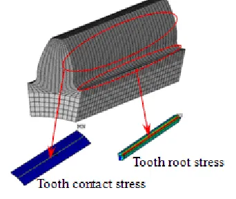
under external load. For spur gear, the contact line between the two tooth surfaces is approximately a straight line. During the meshing process of driving gear, the contact line appears on the position of tooth tip first and then changes to close the position of tooth root. Tooth contact stress appear where the contact line of meshing gear pair appear, tooth root stress of both driven gear and driving gear appear on the position of tooth root respectively which is not in the meshing contact region. The results of gear strength can be read from Figure 2. Select the target element on the position specified of tooth contact stress and tooth root stress, then read the stress of element during the whole gear pair meshing period in the post-processing step. The tooth root stress of driving gear and driven gear should be read respectively, and the tension side should be the standard of tooth root position.
Figure 2: Stress Region Of Analysis Result
3. STUDY OF GEAR STRENGTH FACTORS
3.1 Load Factor and Contact Stiffness Coefficient
[image:2.612.333.504.369.513.2]α =
cos r
T
Fn
1
(3)
Where Tis the transmittable torque of gear pair, r1
and
α
is the pitch radius and pressure angle at pitch cylinder of driving gear respectively,Fn is normalload.
During the working process, actual load that gear may bear is larger than rated load because of many unknown external influence factor. In order to consider the influence that changed load torque caused by these external influence to gear strength, specific load factor should be defined to reflect external factor in the finite element analysis of gear strength. Hence the equation of load calculation about the gear strength can be derived as follows:
L F K
P n
z
ca = (4)
Where, Pcais calculated load, Kzis load factor,
L
is length of line along path of contact.Since the meshing of gear is the contact problem, contact stiffness coefficient is the most important parameter in the contact finite element analysis, which is not only about the material of gear but also about geometrical shapes of the two contact surfaces and applied loads. The contact region of tooth surface keeps changing with time when the both meshing gears are in working condition. The element force between the both contact teeth surfaces interacted through the penetration of element, contact stiffness is similar to spring stiffness defined by penalty function about the contact problem [10]. The contact stiffness coefficient is given from the equilibrium equation as follows:
∆ =k
F (5)
Where, F is contact pressure of meshing tooth surface, k is contact stiffness coefficient, ∆ is intrusion value of contact surface (the amount of spring compression).
The value of contact stiffness is directly related to the contact stress of tooth surface and the meshing position of gear pair, the contact stiffness coefficient should be set reasonably in the finite element analysis of gear strength.
3.2 The Rule of Gear Strength Changed With Relevant Factor
According to the gear strength, these factors which have great influences on the finite element calculation are considered. Take one group of spur gear pair for instance, the main parameters of
considered gears are z1 =30 , z2 =62 , m=2 ,
o 20
=
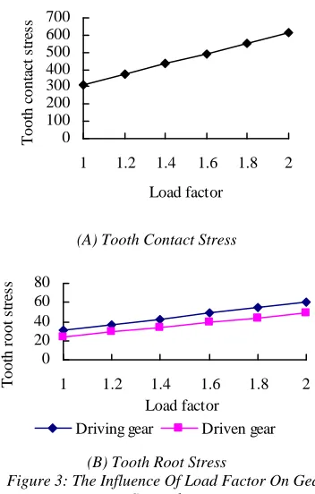
α , b1=60mm , b2=55mm . The finite element model of gear pair is established as shown in Figure 1, dynamic finite element calculation is carried out based on ANSYS through the method by changing the load factor and contact stiffness coefficient. View the tooth surface contact stress and tooth root blending stress, and draw corresponding graphs of stress based on calculations. Figure 3 shows the graph of gear strength that change with load factor. Among them, Figure 3(a) shows the graph of tooth surface contact stress, and the graph of tooth root stress of driving gear and driven gear is illustrated in Figure 3(b).
0 100 200 300 400 500 600 700
1 1.2 1.4 1.6 1.8 2
Load factor
T
o
o
th
c
o
n
ta
ct
s
tr
es
s
(A) Tooth Contact Stress
0 20 40 60 80
1 1.2 1.4 1.6 1.8 2 Load factor
T
o
o
th
r
o
o
t
st
re
ss
Driving gear Driven gear
[image:3.612.330.506.278.554.2](B) Tooth Root Stress
Figure 3: The Influence Of Load Factor On Gear Strength
From the result shown in Figure 3, gear strength is very sensitive to the load factor. With the load factor increase, the value of tooth contact stress and tooth root stress almost grow linearly. The factor should be set correctly based the actual working condition during the finite element analysis of gear strength.
0 70 140 210 280 350
0.010.05 0.1 0.3 0.5 0.7 0.9 1 3 5 7 9 10
Contact stiffness coefficient
T
o
o
th
c
o
n
ta
ct
s
tr
es
s
(A) Tooth Contact Stress
0 10 20 30 40
0.010.05 0.1 0.3 0.5 0.7 0.9 1 3 5 7 9 10
Contact stiffness coefficient
T
o
o
th
r
o
o
t
st
re
ss
Driving gear Driven gear
[image:4.612.92.292.75.379.2](B) Tooth Root Stress
Figure 4: The Influence Of Contact Stiffness Coefficient On Gear Strength
It can be seen from Figure 4 that the influence of contact stiffness coefficient on tooth contact stress is greater than that of tooth root stress. The tooth contact stress is improved and then stable with the increasing contact stiffness coefficient, the turning point of stress comes near the value 1. The tooth root stresses of gears are not changed obviously with the increasing contact stiffness coefficient and remain about the same. By definition of contact stiffness, the target value do not change much with increasing contact stiffness coefficient, at the same time to ensure the convergence of calculation, set small contact stiffness coefficient as far as possible. Thus the value 1 can be defined as the initial value of contact stiffness coefficient in the finite element calculation of gear strength.
4. VERIFIED EXAMPLE
4.1 Gear Strength Example of Finite Element Calculation
[image:4.612.314.544.106.280.2]Take spur gear for example, five groups of gear pairs are considered for the calculation of gear strength based on dynamics finite element analysis. The basic instance parameters of spur gear drive are shown in Table 1, the inferior figure 1 represents driving gear and 2 represents driven gear. Assuming that the whole gear pairs are under light load, the elastic modulus of the material is 206000 and Poisson’s ratio is 0.3.
Table 1: Basic Parameters Of The Spur Gear Drive
Group 1 2 3 4 5
Geometric parameters Number of
teeth
z1 30 13 26 18 20
z2 62 43 79 79 63
Normal
module mn/mm 2 12 25 2 3 Modification
coefficient
x1 0 0.5 0.5 0.8 0.25
x2 0 -0.5 0.5 0.7 0.25
Gear face width
b1/mm 55 180 500 36 60
b2/mm 55 180 500 36 60
Load parameters Rotational
velocity
W1/(r/min
) 1450 97.2 36.5 940 215 Torque T1/Nm 49.4 6600 2616
16 22.5 96.4
Based on the selection methods of application factor and dynamic factor of load capacity calculation for involute spur gears in the traditional method, load factor is defined as the product of application factor and dynamic factor with consideration of working condition. Also the contact stiffness coefficient is set to 1 from the rule shown in Figure 4. Through the finite element calculation of spur gear pairs in the example, the results of gear strength can be obtained. Table 2 shows the finite element results of gear strength.
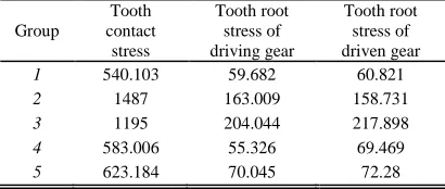
Table 2 : The Finite Element Results Of Gear Strength
Group
Tooth contact
stress
Tooth root stress of driving gear
Tooth root stress of driven gear
1 540.103 59.682 60.821 2 1487 163.009 158.731
3 1195 204.044 217.898 4 583.006 55.326 69.469 5 623.184 70.045 72.28
4.2 Comparison with Traditional Method In order to verify the rationality and validity of the finite element method (FEM) of gear strength, the finite element results are compared with stresses calculated based on traditional ISO method (TM/ISO) of load capacity for spur gear.
[image:4.612.315.520.435.522.2]0 300 600 900 1200 1500
1 2 3 4 5
Number of gear gear
T
o
o
th
c
o
n
ta
ct
s
tr
es
s
[image:5.612.106.302.258.353.2]FEM T M/ISO-P T M/ISO-G
Figure 5: Comparison Of Tooth Contact Stresses According To The Two Methods
0 100 200 300 400
1 2 3 4 5
Number of gear pair
T
o
o
th
r
o
o
t
st
re
ss
o
f
d
ri
v
in
g
g
ea
r
FEM T M/ISO
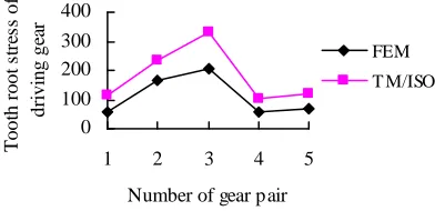
Figure 6: Comparison Of Tooth Root Stresses Of Driving Gear According To The Two Methods
0 100 200 300 400
1 2 3 4 5
Number of gear pair
T
o
o
th
r
o
o
t
st
re
ss
o
f
d
ri
v
en
g
ea
r
FEM
T M/ISO
Figure 7: Comparison Of Tooth Root Stresses Of Driven Gear According To The Two Methods
From the result shown in Figure 5, the results of tooth surface contact stress of both calculation methods are almost equal, and the relative error between the finite element method and the traditional method is approximately 20%. Since the location of the critical section is determined on the dynamic simulation of finite element method, the traditional method assumes the pitch circle of gear as basis of the maximum contact stress. As can be seen from Figure 6 and Figure 7, tooth root stress calculated based on the traditional method is more conservative than that of finite element method, and the relative error of both the two methods is larger with the value 40% approximately. The critical section of tooth root used within ISO standard is determined by the points of tangency of the fillet
with the straight lines inclined at 30°to the tooth center line, which inherits more views of traditional empirical theory. The traditional method is different from the finite element method which is characterized by the simulation of the rotary motion, the critical section of tooth root used in finite element method is determined based the actual tooth profile model of gear pair. In general, both gear strength results of the two methods have the same trend, but the finite element method is more accurate and reliable.
5. CONCLUSION
In this paper a dynamics finite element method is proposed for the accurate numerical analysis of gear strength, which is different from the common static analysis method. A precise finite element model of gear pair has been developed, the results of gear strength includes tooth surface contact stress and tooth root stress is studied to change with load factor and contact stiffness coefficient in the process.
The tooth surface contact stress and tooth root stress are obtained from the dynamics analysis of five groups of spur gear pairs. The finite element results are compared with stresses calculated based on the traditional ISO method, which confirms effectiveness and accuracy of the dynamic method. The dynamics analysis of gear strength overcomes the limitation of the traditional method that is in approximate calculation. The accurate analysis of gear strength in the actual working condition based on the dynamics method can be made. Since the method can be extended to other types of gear because of the general 3D model, it is of great significance to check the gear strength accurately, and provides assurance of strength fatigue analysis and optimization design for gear transmission.
ACKNOWLEDGEMENTS
REFERENCES:
[1] A. Kawalec, J. Wiktor, D. Ceglarek, “Comparative Analysis of Tooth-Root Strength Using ISO and AGMA Standards in Spur and Helical Gears with FEM-Based Verification”, Journal of Mechanical Design, Transactions of the ASME, Vol. 128, No. 5, 2006, pp. 1141-1158.
[2] Ludvik Prasil, Jaroslav Mackerle, “Finite element analyses and simulation of gears and gear drives-A bibliography 1997-2006”, Engineering
Computations: International Journal for
Computer-Aided Engineering and Software, Vol. 25, No. 3, 2008, pp. 196-219.
[3] Tengjiao Lin, H. Ou, Runfang Li, “A finite element method for 3D static and dynamic contact/impact analysis of gear drives”, Computer Methods in Applied Mechanics and Engineering, Vol. 196, 2007, pp. 1716-1728. [4] EI-Sayed S.Aziz, Constantin Chassapis,
“Probabilistic Simulation Approach to Evaluate the Tooth-Root Strength of Spur Gears with FEM-Based Verification”, Engineering, Vol. 3, No. 12, 2008, pp. 1137-1148.
[5] Vera Nikolic, Cemal Dolicanin, Dejan Dimitrijevic. “Dynamic model for the stress and strain state analysis of a spur gear transmission”, Journal of Mechanical Engineering, Vol. 58, No. 1, 2012, pp. 56-67. [6] Andrzej Kawalec, Jerzy Wiktor, “Tooth root
strength of spur and helical gears manufactured with gear-shaper cutters”, Journal of Mechanical Design, Transactions of the ASME, Vol. 130, No. 3, 2008.
[7] Ivana Atanasovska, Vera Nikolić-Stanojlović, Dejan Dimitrijević, et al. “Finite element model for stress analysis and nonlinear contact analysis of helical gears”, Scientific Technical Review, Vol. LVIX, pp. 61-69, 2009.
[8] Xueyi Li, Chaochao Li, Sanshuai Li, Shoubo Jiang, “Contact dynamics analysis of helical gear based on precise tooth surface model”, International Review on Computers and Software, Vol. 7, No. 3, 2012, pp. 1215-1220. [9] Yongjun Wu, Jianjun Wang, Qinkai Han,
“Contact finite element method for dynamic meshing characteristics analysis of continuous engaged gear drives”, Journal of Mechanical Science and Technology, Vol. 26, No. 6, 2012, pp. 1671-1685.