Fuzzy Logic Controller based Wind Power
Generation in a DC Micro Grid
M S Manoja Kumari1, N. Malla Reddy2
1, 2
M.Tech, Dept of EEE, G. Narayanamma Institute of Technology and Science
Abstract: The conventional energy resources are depleting day by day. Non-conventional energy is considered the energy of the future. Considering the benefits of non-conventional energy generation, many countries have started producing the large scale wind energy generating system.
The output power generated by wind energy source is ac power and is converted to dc through rectification process and voltage obtained by this process is attached to the dc grid.
The failure of one generator does not affect the overall system performance i.e., the generators will capable to balance the lagging power. The fuzzy logic controller is the most appropriate for the human decision making mechanism, providing the operation of an electronic system with decision of experts. The main objective is to keep up the voltage across the dc grid which has to be controlled for parallel operation of several wind generations without the need to synchronize the voltage, frequency and phase, thus allowing the wind generators to be turned ON or OFF anytime without causing any disruptions. A dc grid-based wind power generation system with fuzzy controller is used to reduce the total harmonic distortion and improves the power quality. Simulation results are carried out by using MATLAB software.
Keywords:Wind power generation, dc micro grid, Fuzzy logic controller
I. INTRODUCTION
This document is a template. For questions on paper guidelines, please contact us via e-mail Now-a-days there is great raise in the generation of power from renewable energy sources. Generation of power from wind energy is one of the important concept and role in our country. By using the wind power there is drop of demand on the grid. Generally in wind farms the wind speed is not constant. The variation of wind speed in wind farms depends upon the environmental and climate conditions. Thus, the production of power due to wind speed variation and related issues that affect the reliability of power supply and power balance in system connected grid. In recent times the research attention on dc grids has been increasing due to technological advancements in power electronics and energy storage devices the explore on dc micro grids has conducted to facilitate the integration of different distributed energy systems and energy storage systems.
A dc micro grid based wind plant architecture in which each wind energy conversion unit consisting of a matrix converter, a high frequency transformer and a 1-Φ ac/dc converter. The recommended architecture improves the system state as three stages of conversion are essential. In this wind farm architecture the wind turbines are gathered into four groups every group is connected to a converter. Through the existing architecture the failure of functioning of one converter results in unsuccessful operation of all four wind turbines of the group.
The research works are mostly focused on the development of different distributed control strategies to synchronize the operation of various distributed energy systems (DES) and energy storage systems in dc micro grid. The research works generally focused to overcome the challenge of attaining a decentralized control operation using only local variables.
The DES of dc micro grid is robustly coupled to each other and to keep the minimum level of co-ordination among the DES and controllers.
The hybrid ac/dc grid architecture consists of both ac and dc networks connected to bidirectional converter. Hierarchical control algorithms are united to ensure efficient power transfer among the ac micro grid and the dc micro grid in different operating conditions. The failure of bidirectional converter results in the separation of dc micro grid from ac micro grid.
To facilitate increase the controller’s robustness beside various operating conditions wherever the micro grid operates in the grid-connected mode or islanded mode of operation on top of its capability to handle constraints, a model-based model predictive control design is projected for controlling the inverters. Since the micro grid should operate stably in diverse operating conditions, the uses of model predictive control for the control of inverters offer better transient response w.r.to the change in operating conditions.
A. Model Predictive Control
Model predictive control (MPC) is an advanced method of process used in industries, oil refineries and now-a-days it has also been used in power system balancing models. Model predictive controllers depend on dynamic models and most often linear empirical models obtained by system identification. The most important aspect of MPC is the fact that it allows optimized current timeslot, while considering future timeslots in account. MPC can achieve by optimizing a finite time-horizon, but only implementing the current timeslot. Model predictive control has the ability to predict the future events and can take control actions accordingly. MPC is early universally applied as a digital control, although there is research in achieving faster response with specially designed analog circuitry. The models used in Model predictive control are normally intended to represent the functioning of complex dynamical systems. The additional complexity of the Model predictive control algorithm is not generally needed to provide adequate control of simple systems, which are often controlled well by generic PID controllers. Common dynamic characteristics that are difficult for PID controllers include large time delays and high-order dynamics. MPC will predict change in dependent variables that takes place during the process. In the control process the independent variables are adjusted by the controller very frequently either by set of point’s regulatory. PID controllers are the final control elements with independent variables that cannot be tuned by means of the controller are used as disturbances. Dependent elements in this procedure are the measurements of control objectives or constraints. MPC use the current plant measurements and dynamic response of the system function, MPC model is used to check the changeable parameter and their constraint to analyze future variation in the system function. The variations are calculated to seize the dependent variables near to target as looking behind constraints on both independent and dependent variables. The MPC typically sets out to be first change in independent variable to be implemented as vary in parameters that are required in next stage. Linear MPC approach is used in greater part of applications by feedback method of MPC compensating for forecast of errors due to structural variance among the model and the process. In the MPC which consists of only linear models, the superposition rule of linear algebra which enable the effect of vary in multi-independent variables are added together to foresee the response of the dependent elements. Thus simplify the control problem with the series of direct matrix algebra calculation that are quick and robust. While linear models are not amply accurate to signify the real process nonlinearities, a number of approaches can be made. To reduce nonlinearity in certain cases the process variables can be altered before and after the linear MPC model.
II. CONTROL STRATEGY
A. System Explanation
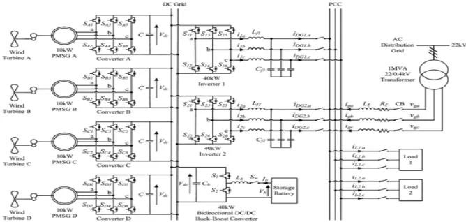
[image:2.612.135.469.552.711.2]The fuzzy logic controller based wind power generation in a dc micro grid composed of multiple parallel connected wind turbines along with generators by eliminating the need of voltage and frequency synchronization. The four 10kW permanent magnet synchronous generators (PMSG) is connected each with three phase converter which acts as rectifier to control dc output voltage from each PMSG to the required value at the dc grid.
The overall collected power across the dc grid is transformed by two inverters are rated at 40 kW. The elimination by individual inverter across output of each wind generator and usage of two inverters among the dc grid and the ac grid is achieved. Dc grid provides power to dc loads by eliminating need of inversion. The synchronization of rectifiers and inverters is accomplished by using centralized energy management system. The EMS monitors and controls the power transmits of each Wind Generator and the load power utilization of micro grid during a centralized server operation. To prevent excessive circulating currents among the inverters and its output voltages are adjusted to equivalent voltage. By using the EMS, the output voltages of inverters 1 and inverter 2 are constantly examined to make sure that the inverters uphold the same output voltages.
The centralized EMS will also look after additional aspects of power management system for example load forecasting, optimum power flow unit commitment and economic dispatch. The information regarding field measurements from transformer tap positions, circuit breaker and smart meters are all connected to the centralized server for dispensation through wireless communication. Throughout grid connected action the two inverters divide the maximum output from the PMSGs that is every inverter shares 20 KW. The highest power produced by each wind turbines is expected from optimal wind power Pwt,opt as follows :
Pwt,opt = kopt(ωr,opt)3 (2)
Kopt = Cp,optρA( )3 (3)
ωr,opt = (4)
Thus kopt is the optimized constant, ωr,opt is the wind turbine speed for optimal power generation, Cp,opt is the optimal power
coefficient of turbine, ρ is air density coefficient, A is coefficient of area swept by rotor blades, λopt is the optimal speed tip ratio, R is radius of blade and ν is wind speed coefficient.
The 80 Ah storage battery (SB) is attached to dc grid all the way through a 40 kW bidirectional buck-boost converter is used for the charging and discharging operations while the micro grid operates in connected or islanded from the grid. The energy constraints of the storage battery during the dc grid are firm based on the system-on-a-chip (SOC) limits given as:
SOCmin < SOC ≤ SOCmax (5)
Although the SOC of storage battery cannot be measured directly, this can be determined through the inference methods. By the usage of dc grid the impact of fluctuations between power generation and load can be condensed as the SB can quickly approach online to control the voltage across dc grid. All though off-peak load require is low the SB is charged up by the overload power generated by the wind generators and during peak load while the high electricity demand, the SB will supply the stored power to the loads.
B. System Operation
All through the operating condition of micro grid the distribution grid is connected the power generated from wind turbines is providing local power support to the loads thus reducing the burden on the power grid. The storage battery is able to control under various demand area management functions for example peak shaving and valley filling depending on value of demand of electricity and SOC of the SB. Throughout the test case of islanded operation the circuit breakers are detached the micro grid from distribution grid, the turbines and the SB are only accessible sources to the load demand supply. The storage battery can provide the shortage of real power to sustain the power balance of the micro grid:
Pwt + Psb = Ploss + Pl (6)
Where Pwt is the real power generated by WT, Psb is the real power supplied via SB which subjects to the restriction of the SB
highest power Psb, maximum that can be delivered through discharge is given as:
Psb ≤ Psb,max (7)
Ploss is loss in the system, and Pl is the real power delivered to the loads.
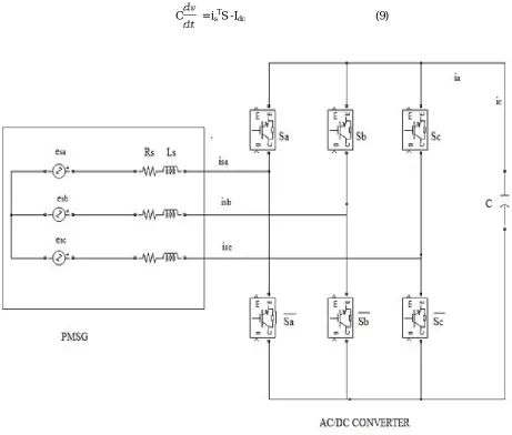
C. AC/DC Converter Model
Fig. 2.2 is power circuit has a PMSG which is set to an ac/dc voltage source converter. The PMSG is designed as a balanced 3-Φ ac voltage source esa, esb, esc are connected in series resistance Rs and inductance Ls. The state equations of PMSG currents isa, isb, isc and dc voltage output Vdc of converter can be given as follows:
C = isTS -Idc (9)
[image:4.612.70.531.76.468.2]Fig 2: Power Circuit Of A Pmsg That Is Connected To An Ac/Dc Voltage Source Converetr
Where
is = [isa isb isc]T , es = [ esa esb esc]T
K =
S = [ Sa Sb Sc ]T is the converter switching functions which are defined as
Sj = for j = a, b, c (10)
D. DC/AC Inverter model
Fig: 3 Single Phase Representation Of The Three Phase Dc/Ac Inverter
Lf + iR + VDG = uVdc (11)
iDG = i – iCf (12)
where Vdc is the dc grid voltage, u is control signal, R is the inverter resistance loss, Lf and Cf are the inductance and capacitance of low-pass-filter (LPF), iDG is the output current of inverter, i is the current passing through Lf , iCf is the current flowing through
Cf , and VDG is the inverter output voltage.
During grid-connected mode the inverters are connected to distribution grid which operates in current control mode (CCM) because frequency and magnitude of the output voltage are fixed.
Hence, the discrete equations for the inverter state space model function in the CCM can be given with sampling time Ts
Ag = 1- , Bg1 = [ 0 - ],
Bg2 = , Cg = 1, Dg = [ ]
Where the subscript ‘g’ indicates the inverter model during grid operating mode, k is discretized present time step and xg (k+1) = Ag xg(k) + Bg1vg(k) +Bg2ug(k) (13)
yg (k) = Cgxg (k) + Dgvg(k) (14)
x g(k) = i(k) is the state vector, vg(k) = [VDG(k + 1) VDG(k)]T is the exogenous input, ug(k) is control signal with −1 ≤ ug(k) ≤ 1
and yg(k) = iDG(k) is output. The exogenous input vg(k) can be considered by state assessment and the grid is set as a large power
system, which means that the 3-Φ grid voltage is stable sinusoidal voltage. Thus the system functioning in the CCM is a 3-Φ sinusoidal signal which can be used as the exogenous input.
As in the islanded operation, the inverters are operated in the voltage control mode (VCM). The voltage across the PCC is maintained in the inverters since the micro grid is islanded from the distribution grid. As compared to Ts change in inverter output current is very slow. Therefore some assumptions are made while deriving state space equations for the inverter function during
VCM is: = 0 (15)
By looking after the earlier assumption, the discrete state space equations of inverter operation in VCM can be given as xi(k + 1) = Ai xi (k) + Biui (k) (16)
yi(k) = Cixi(k) (17)
Where
The model of inverter during islanded operation is given by ’i’ and
Ai = , Bi =
Ci = [ 0 1 0]
xi(k) = [i(k) VDG(k) iDG(k)]T is state vector; ui(k) is control signal with −1 ≤ ui(k) ≤ 1, and yi(k) = VDG(k) is the output. Throughout
E. Control diagram for the AC/DC Converter
Fig.2.4 represents the configuration of controller for ac/dc VSC and is required to keep the dc output voltage Vdc of every converter
Vdc* is due to any power inequality in dc grid. The power imbalance will make as voltage error (Vdc∗− Vdc) at the dc grid, which is
next fed to a PI controller to create a current reference id for id* to track. In order to remove the presence of high frequency switching
ripples across the dc grid, Vdc is first send through a first-order LPF. The current iq to be controlled must be zero so that the PMSG
only delivers real power. The current errors Δidand Δiq are then converted into the abc frame. After conversion they are given to a
proportional resonance (PR) to generate the required control signals using pulse width modulation technique.
Fig: 4 design of proposed controller for the ac/dc converter.
F. Control Design for the DC/AC Inverter
The micro grid is operated in both grid-connected and islanded modes of operation. MPC is a model-based controller and adopts a receding horizon approach. The optimization algorithm will compute a sequence of control actions to minimize the selected objectives for the whole control horizon. It only executes the first control action for the inverter. At the next time step, the optimization process is repeated based on new measurements. MPC can track the output used as reference at the next step it plans and correct its control signals all along the control process. An enhanced transient response is compared to conventional PID/PR controllers. To develop the control algorithm for the inverters, the state-space equations are transformed into augmented state-space equations by defining the incremental variables in the following format:
Δζ(k) = ζ(k) – ζ(k-1) (18)
ξ represents each variable in the inverter model, such as VDG, iDG, i and u as shown in Fig. 2.3. The augmented state space model
for the inverter model operating in the CCM during grid-connected operation by defining the incremental variables can be expressed as follows:
Xg (k+1) = Ag,aug Xg(k) + Bg1aug Vg(k) + Bg2aug Ug (k) (19)
Xg(k) = [Δi(k) iDG(k)]T is the state vector; Vg(k) = [ΔVDG(k + 2) ΔVDG(k + 1) ΔVDG(k]T is the exogenous input; Ug(k) = Δug(k) be
control signal; and Yg(k) = iDG(k) is the output.
In the same way, the augmented state-space model of the inverter model operating in the VCM throughout islanded operation can be given as:
Yg (k) = Cg aug Xg(k) (20)
Where Ag aug =
Bg1aug =
Bg1 aug =
Xg(k) = [Δi(k) iDG(k)]T is the state vector; Vg(k) = [ΔVDG(k + 2) ΔVDG(k + 1) ΔVDG(k]T is the exogenous input; Ug(k) = Δug(k) is
the control signal; and Yg(k) = iDG(k) is the output. in the same way, the augmented state-space model of the inverter model
operating in the VCM during islanded operation can be given as:
Xi(k+1) = Ai aug Xi(k) + Bi aug Ui(k) (21)
Xi(k) = [Δi(k) ΔVDG(k) ΔiDG(k) VDG(k)]T is the state vector; Ui(k) = Δui(k) is the control signal; and Yi(k) = VDG(k) is the output. For
the control of the two augmented models in the CCM and the VCM, the following cost function is solved using quadratic programming in the proposed MPC algorithm.
Yi(k) = Ci aug Xi(k) (22)
Xi(k) = [Δi(k) ΔVDG(k) ΔiDG(k) VDG(k)]Tis the state vector; Ui(k) = Δui(k) is the control signal; and Yi(k) = VDG(k) is the output. For the control of the two augmented models in the CCM and the VCM, the following cost function is solved using quadratic programming
J = (Rs – Yj)T (Rs – Yj) + UjT QUj (23)
Subject to the constraint-1 ≤ uj(k) ≤ 1 (24)
The above equations and there explanation is given in the Ref (1).
III. CONTROLLERS
A. PI Controller
For the elimination of the steady state error resulting from P controller, P-I controller is used. In respect of the speed of the response and overall system stability, thus it has a negative impact and more often used in areas wherever speed of the system is not a problem. P-I controller has no ability to calculate the future errors of system and also cannot reduce the rise time and eliminate the oscillations.
FIG: 5 PI Controller Block
P.I Controller is a control feedback loop that calculates an error signal by taking the difference between the output of a system, in this condition the power being drawn from the battery and the set point.
1) Advantages
a) Zero steady state error
b) Maximum peak overshoot
2) Disadvantages a) High settling time
b) High rise in time
3) Applications a) Liquid flow control
b) Temperature control
B. Fuzzy Logic Controller
Fig : 6 Fuzzy Interference System
C. Fuzzification
The first step for the fuzzy inference process is fuzzification. In this process a domain transformation is taken place where crisp inputs are transformed to fuzzy inputs. Crisp inputs are accurate inputs measured with sensors and passed into the control system for processing of elements like temperature, pressure, rpm's, etc.
D. Defuzzification
This way is used for the process of producing a fuzzified output to a crisp value from a fuzzy set. It is the process that maps a fuzzy set to a crisp set. Centroid method is employed for defuzzification
E. Fuzzy Inference
In this process the given input to an output using fuzzy logic. Fuzzy inference process has been successfully employed in data acquisition, decision analysis, expert systems, and computer vision.
The subsequent steps are used for implementing fuzzy logic controller:
1) Regulate the set of fuzzy rules
2) The inputs are fuzzified using input membership functions.
3) The given inputs are fuzzified based on fuzzy rules.
4) The consequence of the rule are found by combining the rule strength and the output membership function
5) The consequences are combined to get an output distribution.
6) Defuzzifying the output distribution.
Fuzzifying the inputs using the input membership functions:
a) Input 1
Fig: 7 Membership Function For Input 1
[image:8.612.37.570.380.722.2]b) Input 2
c) Output
Fig: 9 Membership Function For Output
F. Fuzzy Rules
Fuzzy rules are used within fuzzy logic systems to infer an output based on input variables.
Fig: 10 Rule Box
1) Advantages
a) Simple sensors can be used; fuzzy logic sometimes uses approximate data.
b) They can be described with little data, so small memory is enough to use.
c) These are often quite understandable.
d) They are robust
2) Disadvantages
a) Computing restrictions are too severe for complete mathematical implementation.
3) Applications
a) Automatic control systems
b) Crisp control signal or decision
c) Embedded systems
d) VLSI microcontroller
e) Hybrid modeling
IV. SIMULATION CIRCUITS AND RESULTS
The dc grid based wind power generation using fuzzy logic controller is implemented using MATLAB and simulation is done. The desired output of the proposed concept is evaluated under different operating conditions.
The system parameters are:
Parameter value
1) Distributed grid voltage Vg = 230 V
2) Dc grid voltage Vdc = 500V
3) PMSG stator impedance Rs=0.2Ω, Ls=2.4mH
4) Distribution line impedance Rl=7.5mΩ, Ll=25.7µH
5) Inverter LC filter Lf=1.2mH,Cf=20µF
6) Converter and inverter loss resistance R=1mH
7) Converter capacitance C=300µF
8) Load 1 rating PL1=35kW, QL1=8kVAr
The efficacy of the system is evaluated under different test cases and there conditions are explained in the chapter 2 in this chapter fuzzy logic controller is used in the circuit are executed and results are give below.
A. Experimental Circuits
This is the main circuit block which consists of PMSG, rectifier and inverter blocks connected to the dc micro grid and distribution grid and it also consists of storage battery. The different test cases which system operates are given as:
1) Test case 1: is failure of inverter during grid connected operation
2) Test case 2: is Connection of AC/DC Converter During Grid-Connected Operation.
3) Test case 3:Islanded Operation.
Fig:11 Dc Grid Based Wind Power Generation In A Micro Grid Block
B. Permanent magnet synchronous generator block:
This block consists of PMSG along with the rectifier circuit and the controller circuit
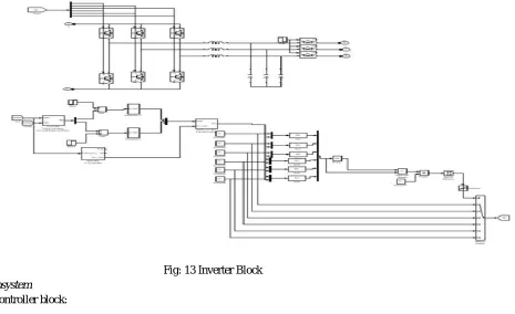
C. Inverter
[image:11.612.73.538.109.393.2]The 3-Φ circuit along with the controller circuit:
Fig: 13 Inverter Block
D. Subsystem
Fuzzy controller block:
FIG: 14 FUZZY BLOCK
E. Simulation Results
[image:11.612.117.493.606.701.2]1) Case 1: Failure of inverter during grid connected operation: In this test case the micro grid is working in grid connected mode of operation the power generated by the system during load demand. The normal operating condition of the inverter 1 and 2 will supply power to the loads, when one of the inverter fails to function and that need to be separated from the grid and other inverter must able to handle power generated by the permanent magnet synchronous generators and should give the continuous supply to the loads. The wave forms of the real and reactive power of the system across the inverter 1, inverter 2 and across load are shown. The real power, reactive power, dc grid voltage and the current across the grid are shown in waveforms.
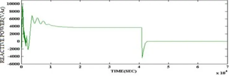
Fig : 16 Reactive Power Delivered By Inverter 1
Fig : 17 Real Power Delivered By Inverter 2
[image:12.612.122.492.86.210.2]Fig : 18 Reactive Power Delivered By Inverter 2
[image:12.612.96.499.585.718.2]Fig: 20 Reactive power Delivered By The Grid
Fig: 21 Real Power Consumed By The Loads
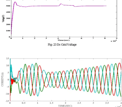
Fig: 23 Dc Grid Voltage
Fig: 23 Grid Current
[image:14.612.97.500.598.727.2]2) Case 2: Connection of AC/DC Converter During Grid-Connected Operation: In this test case when the PMSG is under the fault condition or under maintenance after clearing the fault the converter is attached to the grid .The enhancement of the projected dc grid based wind power system is that it assist the connection of any PMSGs to the micro grid without need to synchronize their voltage and frequency. The wave forms of the real and reactive power of the system across the inverter 1, inverter 2 and across load are shown. The real power, reactive power, dc grid voltage and the current across the grid are shown in waveforms.
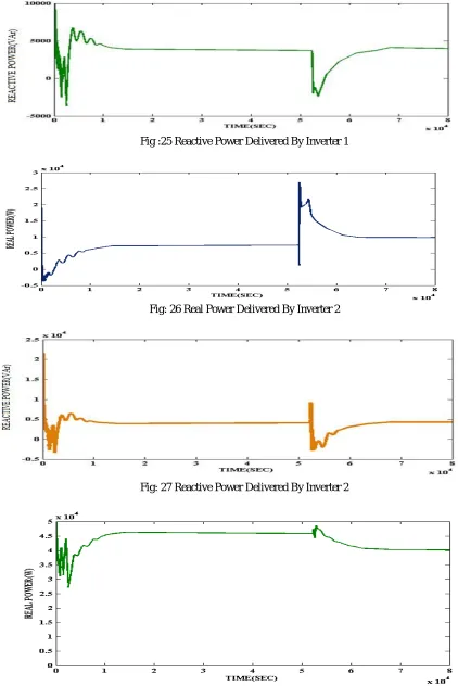
Fig :25 Reactive Power Delivered By Inverter 1
Fig: 26 Real Power Delivered By Inverter 2
Fig: 27 Reactive Power Delivered By Inverter 2
Fig: 29 Reactive Power Delivered By The Grid
Fig: 30 Dc Grid Voltage
3) Case 3: Islanded Operation: In this test case the micro grid is islanded from the distribution grid, if there is any fault in the distribution side at that condition the total generated power from the PMSGs will be inadequate to supply for all the load demand. During this the SB is essential to supply power to ensure that the micro grid continues to deliver the power to the load. The wave forms of the real and reactive power of the system across the inverter 1, inverter 2 and across load are shown. The real power, reactive power, dc grid voltage and the current across the grid are shown in waveforms.
Fig: 32 Real Power Delivered By The Grid
Fig: 33 Reactive Power Delivered By The Grid
Fig: 35 Reactive Power Delivered By The Inverter 1
Fig: 36 Real Power Delivered By The Inverter 2
Fig: 37 Reactive Power Delivered By The Inverter 2
Fig: 39 Dc Grid Voltage
Fig: 40 Grid current
Table 1: Comparison table for total harmonic distortion of grid current
CONDITION PI FUZZY
Case 1:Failure of one inverter during grid connected operation
18.28 1.75
Case 2:Connection of ac/dc converter during grid-connected operation
16.43 2.13
Case 3:Islanded operation 19.11 2.02
V. CONCLUSION
REFERENCES
[1] Control and Operation of a DC Grid-Based Wind Power Generation System in a Micro grid K. T. Tan, Member, IEEE, B. Sivaneasan, Member, IEEE, X. Y. Peng, Student Member, IEEE, and P. L. So, Senior Member, IEEE.
[2] An Improved Control Strategy for DC Grid - Based Wind Power Generation System in a Micro grid G. Ganesan, R. Sathiskumar PG Scholar, Department of Power System Engineering, Anna University Regional Campus, Madurai, Tamil Nadu, India1 Assistant Professor, Department of Electrical and Electronics Engineering, Anna University Regional Campus, Madurai, Tamil Nadu, India2
[3] X. Liu, P. Wang, and P. C. Loh, “A hybrid AC/DC microgrid and its coordinationcontrol,”IEEETrans.SmartGrid,vol.2,no.2,pp.278–286, Jun. 2011.
[4] J. A. P. Lopes, C. L. Moreira, and A. G.Madureira, “Defining control strategies for micro grids islanded operation,” IEEE Trans. Power Syst., vol. 21, no. 2, pp. 916–924, May 2006.
[5] S. Kouro, P. Cortes, R. Vargas, U. Ammann, and J. Rodr´ıguez, “Model predictive control—A simple and powerful method to control power converters,” IEEE Trans. Ind. Electron., vol. 56, no. 6, pp. 1826–1838, Jun. 2009
[6] W. Lu and B. T. Ooi, “Optimal acquisition and aggregation of offshore wind power by multi terminal voltage-source HVDC,”IEEE Trans. Power Del., vol. 18, no. 1, pp. 201–206, Jan. 2003
[7] A. Mogstad, M. Molinas, P. Olsen, and R. Nilsen, “A power conversion system for offshore wind parks,” in Proc. 34th IEEE Ind. Electron., 2008, pp. 2106– 2112
[8] http://www.arpapress.com/Volumes/Vol3Issue1/IJRRAS_3_1_11.pdf
[9] P.Cortes, G.Ortiz, J.I.Yuz, J.Rodriguez, S.Vazquez,andL. G.Franquelo, “Model predictive control of an inverter with output LC filter for UPS applications,”
IEEE Trans. Ind. Electron., vol. 56, no. 6, pp. 1875–1883, Jun. 2009
[10] http://www.cs.princeton.edu/courses/archive/fall07/cos436/HIDDEN/Knapp/fuzzy004.htm#I5
[11] M. Falahi, S. Lotfifard, M. Eshani, and K. Butler-Purry “Dynamic model predictive-based energy management of DG integrated distribution systems,” IEEE Trans. Power Del., vol. 28, no. 4, pp. 2217–2227, Oct. 2013