R E S E A R C H
Open Access
Beamforming design with proactive
interference cancelation in MISO interference
channels
Yang Li, Yafei Tian
*and Chenyang Yang
Abstract
In this paper, we design coordinated beamforming at base stations (BSs) to facilitate interference cancelation at users in interference networks, where each BS is equipped with multiple antennas and each user is with a single antenna. By assuming that each user can select the best decoding strategy to mitigate the interference, either canceling the interference after decoding when it is strong or treating it as noise when it is weak, we optimize the beamforming vectors that maximize the sum rate for the networks under different interference scenarios and find the solutions of beamforming with closed-form expressions. The inherent design principles are then analyzed, and the performance gain over passive interference cancelation is demonstrated through simulations in heterogeneous cellular networks.
Keywords: Coordinated beamforming; Proactive interference cancelation; Interference channels; Heterogeneous networks
1 Introduction
One of the key features of the fifth generation cellular networks is ultra dense and heterogeneous [1], where the interference generated by different base stations (BSs) is more complicated. Depending on the locations, the users may experience different levels of interference.
Various BS cooperation techniques have been proposed to mitigate inter-cell interferences. A stronger form of cooperation is so called “CoMP-JP” (Coordinated Multi-Point Transmission with Joint Processing) [2, 3], where the antennas from multiple BSs act as a single antenna array, and the inter-cell interference is transferred into useful signals. However, this kind of schemes require sharing large amounts of user data over finite-capacity backhaul links and assume that BSs have full channel state informa-tion (CSI) of all the active users in the system. In contrast, the CoMP coordinated beamforming (CB) scheme only requires sharing the CSI of the interfered users among cooperated BSs and is therefore more feasible for practical implementations [4–10].
For multi-input-multi-output (MIMO) interference channels, the optimal beamforming design is not an easy
*Correspondence: [email protected]
School of Electronics and Information Engineering, Beihang University, 37 Xueyuan Road, Haidian District, Beijing 100191, People’s Republic of China
task, because the achievable rate of each user depends on the beamforming of all BSs [11]. Most of the exist-ing researches focus on linear transceiver design, where the signal and interference are separated into orthogo-nal subspaces. However, if each coordinated BS does not have more antennas than the number of users in the network, we must perform user scheduling first so that the orthogonal-based CB can remove all the interferences in the scheduled user group. On the other hand, if the interference is very weak or very strong, it is a waste of spatial resource to provide an orthogonal subspace for each interference. In fact, for weak interference channels, treating the interference as noise is optimal [12, 13]. For strong interference channels, interference cancelation can achieve the capacity [14]. For the more general mixed interference channels, the capacity region is unknown and the achievable sum-rate expression is non-convex over the precoding matrices, there is no efficient algorithm available to find the optimal precoding matrices [15].
In [16], six interference scenarios for a single-antenna two-cell network were characterized, where the users respectively experience very strong, strong, mixed 1, mixed 2, weak, and very weak interferences. For each sce-nario, a corresponding transmission scheme to achieve the capacity or the best known achievable rate was
© 2015 Li et al.Open AccessThis article is distributed under the terms of the Creative Commons Attribution 4.0 International License (http://creativecommons.org/licenses/by/4.0), which permits unrestricted use, distribution, and reproduction in any medium, provided you give appropriate credit to the original author(s) and the source, provide a link to the Creative Commons license, and indicate if changes were made. The Creative Commons Public Domain Dedication waiver
designed, and the concept of proactive interference can-celation was proposed for strong and mixed interference scenarios. The basic idea of proactive interference cance-lation is to guarantee strong interference to be decodable and hence can be thoroughly canceled at the receiver by designing the transmitter. This is distinct from an exist-ing interference cancelation scheme, which waits for the opportunity until the interference becomes strong enough to be decodable [17]. In [18], the idea was extended to MIMO interference channels in the mixed interference scenario, where a coordinated precoding method was developed to facilitate proactive interference cancelation. Since the sum-rate expression is a non-convex function of the precoding matrices, an iterative solution was found through convex relaxation.
In this paper, we consider a transmission scheme design for multi-input-single-output (MISO) interference chan-nels. In [19], a parameterization of the beamforming that achieves the Pareto boundary of the achievable rate region was proposed, where a brute-force searching is required to find the solutions. In [20], a more efficient method was proposed to find the Pareto-optimal beamforming vec-tors, which however needs a line searching, and to solve a cubic equation at each search point.
Considering that closed-form transceivers are highly desirable for practical systems, we employ an alterna-tive approach to design the coordinated beamforming that assists proactive interference cancelation for MISO interference channels. Specifically, we assume that each receiver is able to choose the best decoding strategy to mitigate the interference, either decoding the interfer-ence first and then canceling it when it is strong or treating it as noise when it is weak. To maximize the sum rate, the strong interference might need to be fur-ther strengthened to increase the interference-to-signal-plus-noise ratio (ISNR), and the weak interference might need to be further weakened to increase the signal-to-interference-plus-noise ratio (SINR). Inspired by such an intuition, we formulate the optimization problem for designing linear beamforming that maximizes the sum rate with given decoding methods under different interfer-ence scenarios. Beamforming vectors with explicit expres-sions are then provided. Simulation results show that the proposed transmission scheme is superior to existing schemes in heterogeneous networks (HetNets).
The rest of this paper is organized as follows. In Section 2, we first introduce the system model and the transmission scheme with proactive interference cance-lation. Then, we formulate the optimization problem to find the beamforming that maximizes the sum rate in Section 3. The closed-form solution of the corresponding problem in four scenarios is found in Section 4, and the performance in HetNets is evaluated in Section 5. Finally, Section 6 concludes the paper.
2 System model and transmission scheme
In this section, we introduce the system model and the transmission scheme with proactive interference cancelation.
2.1 System model
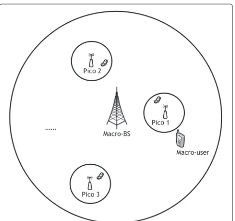
Consider a HetNet scenario as shown in Fig. 1, where one macro-cell coexists with pico-cells in the same fre-quency band. To obtain a closed-form solution and gain useful insight, we first consider a two-cell MISO network consisting of one macro-cell and one pico-cell in the opti-mization and then extend the designed beamforming to multi-cell networks.
For the convenience of expression, we assume the macro-BS and pico-BS as BS1and BS2, respectively.
Cor-respondingly, the macro-user is user 1 and the pico-user is user 2. Each BS knows the channel information from itself to both users. Thei-th BS,i∈ {1, 2}, is equipped withMi antennas, and each user is equipped with a single antenna.
The symbol received at useriis
yi=hHiivixi+hHijvjxj+ni, i,j∈ {1, 2}, j=i, (1)
where hji ∈ CMi denotes the channel vector from BSi to userj,xi is the symbol transmitted by BSiwith power
E[|xi|2]= Pi,vi ∈ CMiis the transmit beamforming vec-tor at BSiwith unit-normvi =1, andniis the Gaussian white noise at useriwith zero mean and unit variance.
2.2 Transmission scheme
The transmission scheme with proactive interference can-celation includes transmit beamforming and decoding.
We first decide the decoding methods for two users according to interference scenarios as follows. (a) When both users suffer weak interference, the desired signals are decoded directly by treating the interference as noise at both users. (b) When one user suffers strong interference while the other suffers weak interference, the strong inter-ference is decoded and subtracted before the desired sig-nal is decoded, and the weak interference is simply treated as noise. (c) When both users suffer strong interference, both users first decode and subtract the interference and then decode the desired signals.
A similar classification of the interference scenarios has been introduced in [15] and [21]. Since we do not know whether the interference is strong or weak before beam-forming, we will find the optimal beamforming vectors for each of the three decoding methods and then choose the scheme that achieves the highest sum rate.
3 Problem formulation
Given the decoding method at each user, we can obtain the sum rate as a function of the beamforming vector, from which we can formulate the optimization problem to find the beamforming that maximizes the sum rate.
(a) Both users treat the interference as noise:When both users are subject to weak interference that is not able to be decoded correctly, the interference can be treated as noise at each user. If the SINR at each user is high, i.e.,
SINRi1, where
SINRi=
Pi|hHiivi|2
Pj|hHijvj|2+1
, i,j∈ {1, 2}, j=i, (2)
then the achievable sum rate can be approximated as
Rweak(v1,v2)=
This approximation will lead to at most 1 bps/Hz loss in an achievable rate of each user in this scenario, because
log2(1+t)−log2t=log21+t−1≤1 (t≥1). (4)
(b) One user decodes the interference:This is a scenario of mixed interference. When user 1 suffers strong inter-ference while user 2 experiences weak interinter-ference, the strong interference should be decoded and canceled at user 1 and the weak interference at user 2 can be treated as noise. Similar to the previous case, we assume high SINR at user 2, i.e., SINR2 1. At user 1, the interference
should be much stronger than the desired signal and the
noise in order to be decodable, hence we can apply a high ISNR assumption, i.e., ISNR11, where
ISNRi=
Pj|hHijvj|2
Pi|hHiivi|2+1
, i,j∈ {1, 2}, j=i. (5)
User 1 decodes and subtracts the interference caused by BS2, and then the desired signal from BS1is decoded in
an interference-free environment, thus the achievable rate of user 1 is log21+P1|hH11v1|2
. The achievable rate of user 2 is upper bounded by log2(1+ISNR1)and log2(1+
SINR2)simultaneously, since the signal from BS2should
be decodable both at user 1 and user 2. Similar to the previous case, under the assumption of high ISNR1and
SINR2, the achievable sum rate can be approximated as
Rmixed1(v1,v2) ≈ log21+P1|hH11v1|2
+log2(min(ISNR1, SINR2)).
(6)
If user 1 treats the interference as noise and user 2 decodes it, the achievable sum rate can be approximated similarly to (6) as
Rmixed2(v1,v2) ≈ log21+P2|hH22v2|2
+log2(min(ISNR2, SINR1)).
(7)
(c) Both users decode the interference:When both users suffer strong interference, they decode and cancel the interference first and then decode their desired signals. Since the interference should be much stronger than the desired signal and the noise, it is reasonable to assume high ISNR at each user, i.e., ISNRi1,i=1, 2.
To ensure the interference caused by BS1to be
decod-able at user 2, the achievdecod-able rate of user 1 should be upper bounded by log2(1 + ISNR2). Similarly, the
achievable rate of user 2 should be upper bounded by log2(1 + ISNR1). After decoding the interference, each
user decodes the desired signal without interference. Therefore, the achievable rate of user i is also upper bounded by log21+Pi|hHiivi|2
. Then, the achievable sum rate can be approximated as
Rstrong(v1,v2)
The approximation in case (c) will lead to at most 1 bps/Hz per-user rate loss as in case (a), and in case (b), it will loss at most 1 bps/Hz at only one user.
Among these cases, the best achievable scheme will be selected as the final transmission scheme. Such problem to find the optimal beamforming can be formulated as
s.t. vi =1, vi∈CMi,i=1, 2. (9b) 4 Beamforming design with closed form
In this section, we strive to find a closed-form solution of problem (9). To this end, we need to find the beamform-ing vectors that respectively maximize the achievable sum rates in four scenarios,Rweak,Rmixed1,Rmixed2, andRstrong.
4.1 Both users treat the interference as noise
For the scenario where both users treat the interference as noise, the achievable sum rateRweakin (3) is rewritten as
log2
The maximization of (10) can be achieved by solving the generalized Rayleigh quotient problem as follows
max vi
PivHi hiihHiivi
vHi Bjivi
, (11)
whose solution is given by generalized eigenvalue decom-position
hiihHiivi=λiBjivi, (12)
whereBji = PihjihHji +IMi andλi is the unique nonzero eigenvalue ofB−ji1hiihHii. Considering the unit-norm con-straint of the beamforming vector, we can obtain
vweaki = B
−1
ji hii
B−ji1hii
, i=1, 2, (13)
which is one of the generalized eigenvectors associated to λi. Note that this result was also obtained in [7]. From the optimization problem, we can see that the beamform-ing vector is to maximize the signal-to-leakage-plus-noise ratio (SLNR).
4.2 One user decodes the interference
For the scenario where user 1 suffers strong interference and user 2 experiences weak interference (the scenario where user 1 experiences weak interference and user 2 suffers strong interference is similar and hence omitted), from (6), the achievable sum rateRmixedcan be expressed as
Sincev1appears only in the second term of the
mini-mum function above, the optimal solutions ofv1andv2
that maximize (14) can be found successively. Specifically,
we can first findv1 by solving the generalized Rayleigh
quotient problem as follows
max v1
vH1B11v1
vH1B21v1
, (15)
whose solution is the generalized eigenvector associated to the largest generalized eigenvalueλmax, which is
B11v1=λmaxB21v1. (16)
Thus, we can obtain
vmixed1 =νmax
B−211B11
, (17)
whereνmax(A)is the unit-norm eigenvector
correspond-ing to the largest eigenvalue ofA.
Then, we find the solution ofv2. Substitutingλmaxinto
(14), we can obtain the optimization problem for v2 as
follows
Sinceλmaxis a positive real number, (18) can be further
simplified as
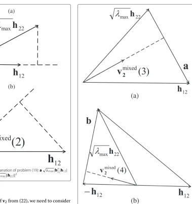
To better understand problem (19), we provide its geo-metric explanation in Fig. 2. Sincev2is a unit-norm vector
inCM2, finding the solution of problem (19) is equivalent
to finding a direction vector that maximizes the minimum of projections ofh12and√λmaxh22on it.
Case 1:If the projection of√λmaxh22on the direction
vector h12
Case 2: If the projection of h12 on the direction
vector
Case 3: Besides these two cases, the optimal solution
will be obtained when the following equality holds
|hH12v2| = | λmaxhH22v2|, (22)
which is due to the nature of the maximization of the min-imum function and the continuity of the two terms. The solution will be located in a two-dimensional subspace of
(a)
(b)
Fig. 2The geometrical explanation of problem (19):a√λmax|hH
22h12|
≥ h122;b|hH
12h22| ≥
√
λmaxh222
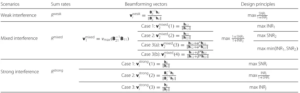
To find the solution ofv2from (22), we need to consider
two subcases based on the projection angle ofh12andh22,
as shown in Fig. 3.
Case 3(a): If the real part of hH12h22 is positive, i.e.,
RhH12h22
> 0, the solution ofv2is in the direction of
the altitude of the acute triangle as shown in Fig. 3(a). Denotea h12−√λmaxh22, which is the third edge of
the triangle. Leth12+αh22denote an arbitrary vector in
the two-dimensional subspace, whereα is the weighting coefficient. Sincevmixed2 is perpendicular toa, by solving the equationaH(h12+αh22) = 0, we obtain the optimal
weighting coefficient asα∗ = −aHh12
aHh
22. Then, the solution
is
vmixed2 (3)= h12+α ∗h
22 h12+α∗h22
. (23)
Case 3(b):IfR(hH12h22)≤0, the solution ofv2is in the
direction of the altitude of the complementary triangle, as shown in Fig. 3(b). Denoteb h12+√λmaxh22, which
is the third edge of the complementary triangle. Similar
Fig. 3The geometrical explanation of problem (22):aRhH12h22
>0; bRhH12h22
≤0
to Case 3(a), sincevmixed2 is perpendicular tob, by solv-ingbH(h12+βh22)=0, we obtain the optimal weighting
coefficient asβ∗= −bHh12
bHh
22 and obtain the solution in this
subcase as
vmixed2 (4)= h12+β ∗h
22 h12+β∗h22
. (24)
4.3 Both users decode the interference
In a strong interference scenario, we maximize the achiev-able sum rateRstrongin (8), which can be written as
log2
⎛ ⎝ 2
i=1,j=i min
Pi|hHjivi|2
Pj|hHjjvj|2+1
, 1+Pi|hHiivi|2
⎞ ⎠.
Denotef1(v1) P1|hH21v1|2,f2(v2) P2|hH12v2|2, and ing the product in (25), the maximization of (25) can be simplified as
whose solution is the maximum of the solutions to the following three subproblems.
It is hard to solve these three optimization subproblems directly since the constraints are non-convex. To obtain beamforming vectors with explicit expressions, we find the solutions in the following way and allow a suboptimal solution.
Case 1: We first maximize (27a) without any
con-straints, and the solution is given by
vstrongi (1)= hii
hii
, i=1, 2. (30)
Then we substitute (30) into (27b) to check whether the constraint is satisfied.
If (27b) can be satisfied,vstrongi (1) in (30) is the opti-mal solution of problem (27). Moreover, it must be the global optimal solution of problem (26), since the max-imization values of the objective functions of problems
(28) and (29) must be smaller than the objective function in (27a), which is determined by (28b) and (29b).
If (27b) cannot be satisfied, the optimal solution of prob-lem (27) is obtained when the equality in (27b) holds, which can be found from problem (29).
Case 2: Next, we maximize (28a) without any
con-straints, which is a generalized Rayleigh quotient problem. Similar to (13), we can obtain
vstrongi (2)= B −1
ii hji
B−ii1hji
, i=1, 2. (31)
Substitute (31) into (28b) to check whether the constraint is satisfied. If (28b) can be satisfied, vstrongi (2) in (31) is the optimal solution of problem (28), which must be the global optimal solution of problem (26) as well. If (28b) cannot be satisfied, the optimal solution of problem (28) is obtained when the equality in (28b) holds. The problem can be included into problem (29) as well.
Case 3: Besides these two cases, the solution of
prob-lem (26) is obtained by solving the subprobprob-lem (29). If we remove the constraint in (29b), a simple solution can be obtained as
vstrongi (3)= hji
hji
, i=1, 2. (32)
This solution is optimal when it satisfies constraint (29b), otherwise it is suboptimal.
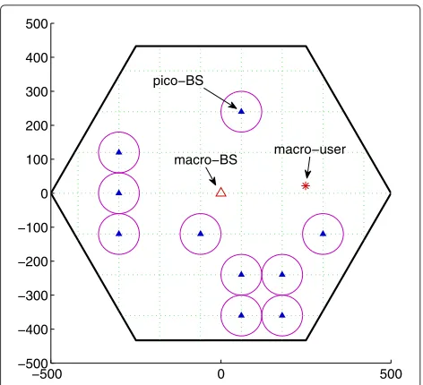
4.4 Summary and interpretation
The beamforming vectors optimized for the typical inter-ference scenarios are summarized in Table 1, where in each scenario, the users apply different decoding meth-ods. From the previous optimization procedure and the expression of each optimal beamforming vector, we can interpret the principle behind the optimal beamforming design for each scenario.
In weak interference scenario, the beamforming vectors at both BSs essentially maximize the SLNR, as we have explained in Section 4.1.
Table 1Summary of optimal beamforming vectors and design principles
Scenarios Sum rates Beamforming vectors Design principles
Weak interference Rweak vweak
i =
Mixed interference Rmixed vmixed
1 =νmax(B−121B11)
Case 3(a):vmixed
2 (3)= h12+α
∗h22
h12+α∗h22 max min(INR1, SNR2)
Case 3(b):vmixed
2 (4)= h12+β
∗h
22
h12+β∗h22
Strong interference Rstrong
In the mixed interference scenario where user 1 is sub-ject to strong interference, the beamforming vector at BS1
also maximizes the SLNR since BS1generates weak
inter-ference; while the beamforming vector at BS2depends on
how strong the interference BS2might generate.
Specif-ically, when the interference caused by BS2 is not very
strong, the beamforming vector is to match the cross-link channelh12 in order to maximize the INR1, i.e., to
strengthen the interference. When the interference from BS2 is very strong, the beamforming vector only needs
to match the direct-link channelh22such that maximizes
the SNR2. When the interference level is in between, we
need to find a trade-off between maximizing INR1 and
maximizing SNR2.
In the strong interference scenario, the beamforming vector at each BS depends on the interference level. When the interference is very strong, the beamforming only maximizes the SNR. When the interference is not very strong, the beamforming should maximize the INR. When the interference level is in between, the beam-forming is to maximize the leakage-to-signal-plus-noise ratio.
Compared with the conventional passive interfer-ence cancelation scheme, the proposed beamforming scheme requires higher complexity in implementa-tions. The increased complexity mainly exists in two aspects. The first is the CSI exchange among the coor-dinated BSs, but this is a common requirement for all CB schemes. The second is the BS calculation before the beamforming selection. For the proposed scheme, each BS has to calculate the sum rate of several possible transmission schemes according to different decoding sequence, and for each decoding sequence, there is a corresponding beamforming design. Finally, each BS will choose the beamforming vector that results in the high-est sum rate. However, since the involved calculations are all in closed form, the increased complexity is not high.
4.5 Extension to multiple pico-cells scenario
In a practical scenario where one macro-cell coexists with N pico-cells, we can first select a pico-BS closest to the macro-user as BS2 then design beamforming vectorsv1
andv2for the macro-BS and the selected pico-BS using
the above principles as if there are only two cells and obtain their data rateR1andR2.
For any other pico-BSs, assuming they are BSj, j = 3, 4,. . .,N+1, beamforming vectorvjis designed accord-ing to the particular interference scenario consideraccord-ing the already determinedv1andR1. For example, if pico-user jis subject to weak interference from the macro-BS, the beamforming vector of BSjcan be designed as in the weak interference scenario, i.e., maximizing the SLNR. Thus, we can obtain
If pico-userjsuffers strong interference from the macro-BS, beamforming vectorvjshould guarantee the interfer-ence from the macro-BS to be decodable at pico-userj, i.e., BSjmight proactively mismatch its direct-link channel to keep the required ISNR. Specifically, in order to ensure the interference from the macro-BS to be decodable, the ISNR at pico-userjshould be strong enough so that
log21+ISNRj
Using the above constraint, after decoding and cancel-ing the interference, the data rate of pico-userjis upper bounded by
In addition, Rstrongj is also upper bounded by the
maxi-mum of log21+SNRj data rate of pico-userjis
Rstrongj =min
log2INRj−R1,Rmaxj
. (36)
Consequently, if log2INRj
Otherwise, the optimal beamforming vector is obtained when the equality in (35) holds, which is
log2(1+Pj|hHjjvj|2)=log2(INRj)−R1. (38)
Denoteθjas the projection angle betweenhjjandvj. The optimal beamforming vectorvstrongj (2)is an arbitrary unit-norm vector satisfying
In this section, we evaluate the performance of the pro-posed beamformers with proactive interference cancela-tion (PIC) in HetNets by comparing with other schemes.
0 50 100 150 200 250 300 350 400 6.5
7 7.5 8 8.5 9 9.5 10
Distance between Macro−BS and Pico−BS (m)
Average Sum−Rate (bps/Hz)
Pareto−optimal PIC
Maximal−SLNR ZF − CB MF − IC
Mixed 2
Strong
Mixed 1
Weak
Fig. 4Average sum rates of different schemes in a two-cell HetNet when the pico-BS moves from macro-cell center to macro-cell edge
BS and interference cancelation at each user (MF-IC) [17]. In addition, the Pareto-optimal beamforming method [20] is simulated and compared.
In the simulation, all BSs are equipped with two anten-nas, and each BS serves one user. The radiuses of the macro-cell and each pico-cell are 500 and 60 m, respec-tively. The transmit powers of the macro-BS and each pico-BS are 46 and 30 dBm, respectively. The noise power is determined by the cell edge SNR of the macro-cell, which is set as 5 dB. The path loss follows 3GPP chan-nel model [22], and the small-scale chanchan-nel is subject to Rayleigh fading. All the simulation results are obtained from 1000 channel realizations.
To show the performance under different interference scenarios, we first consider a two-cell HetNet and fix the position of the user at 250 m away from the macro-BS and move the pico-macro-BS from the macro-cell center to the macro-cell edge while keeping the relative position between the pico-BS and the pico-user fixed. The aver-age sum rates of the considered transmission schemes are shown in Fig. 4. Comparing the sum rates achieved in different interference scenarios, we can see that as the pico-BS moves, the system successively experiences mixed 2, strong, mixed 1, and weak interference scenarios. Since both the beamforming designs and the decoding meth-ods are different under different interference scenarios, the trend of the average sum rate of PIC varies in Fig. 4. In all scenarios, PIC approaches very closely to the Pareto-optimal scheme and outperforms all other schemes. The maximal-SLNR scheme is inferior to PIC in all scenar-ios except for the weak interference scenario. The average
sum rate of ZF-CB is nearly constant in all interference scenarios, because the interference is orthogonal in spatial subspace to the desired signal. MF-IC has a similar trend with PIC but is inferior to PIC due to passively waiting for proper opportunities of canceling the interference.
Next, we will demonstrate the performance of PIC in HetNet with multiple pico-cells. As shown in Fig. 5, we consider a scenario where multiple pico-cells are randomly deployed in the macro-cell and the minimum
−500 0 500 −500
−400 −300 −200 −100 0 100 200 300 400 500
macro−BS macro−user pico−BS
0 5 10 15 20 5
10 15 20 25 30 35 40 45 50 55
Avergate Sum−Rate (bps/Hz)
Pareto−optimal PIC
Maximal−SLNR ZF−CB MF−IC
Fig. 6Average sum rates of different schemes with multiple pico-cells coexisting with the macro-cell
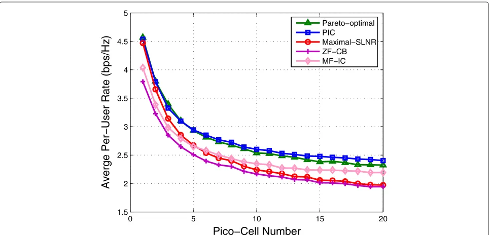
distance among the pico-BSs is 120 m. In the simula-tion, the position of the macro-user is still fixed at 250 m away from the macro-BS and the positions of pico-users are randomly distributed in the pico-cells. Figures 6 and 7 show the average sum rates and per-user rates of dif-ferent schemes with the changing number of pico-cells, respectively. We can see that, although the sum rates of all five schemes increase as more pico-cells coexist, the
PIC scheme increases the fastest. It is surprising that the Pareto-optimal scheme performs worse than the PIC scheme when the pico-cell number exceeds 5. As we have discussed, the Pareto-optimal scheme is originally designed for a two-cell scenario. To apply it in Het-Net with multiple pico-cells, we use the same extension approach as used for a PIC scheme. We first select a pico-BS closest to the macro-user and design beamforming
0 5 10 15 20 1.5
2 2.5 3 3.5 4 4.5 5
Averge Per−User Rate (bps/Hz)
Pareto−optimal PIC
Maximal−SLNR ZF−CB MF−IC
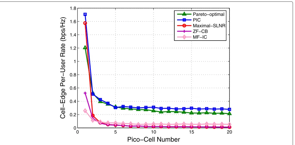
0 5 10 15 20 0
0.2 0.4 0.6 0.8 1 1.2 1.4 1.6 1.8
Cell−Edge Per−User Rate (bps/Hz)
Pareto−optimal PIC
Maximal−SLNR ZF−CB MF−IC
Fig. 8Cell edge per-user rate with multiple pico-cells coexisting with the macro-cell
vectors for the macro-BS and the selected pico-BS using the Pareto-optimal method as if there are only two cells. Then the beamforming vectors of other pico-BSs are designed according to the particular interference scenario considering the already determinedv1andR1. Since the
Pareto-optimal scheme is not optimized for a multi-cell scenario, if the data rate of the macro-user is higher, it is possible to sacrifice the data rate of other pico-users and thus achieves a lower sum rate.
Figure 8 shows the cell edge per-user rates of the five schemes with the changing number of pico-cells. Note that the cell edge per-user rate is a statistic average counted from the worst served 5 % users, which does not imply the users are really located in the cell edge. It is shown that the PIC scheme outperforms the Pareto-optimal scheme and is much better than the maximal-SLNR, ZF-CB, and MF-IC schemes. For example, when 20 pico-cells coexist with the macro-cell, the cell edge per-user rate of the PIC scheme is about six times larger than that of the MF-IC scheme. As a consequence, the PIC scheme has great potential to improve the ubiquitous user experience in cellular networks.
6 Conclusions
In this paper, we proposed a transmission scheme for MISO interference channels. Specifically, we optimized the transmit beamforming that maximizes the achievable sum rate, given the best decoding methods for weak, mixed, and strong interference scenarios. Closed-form solutions of the optimal beamforming were obtained and the underlying design principles were interpreted.
By proactively strengthening the interference with the optimized beamforming to ensure the interference to be correctly decoded and then subtracted at the receiver, the proposed scheme outperforms existing schemes of passive interference cancelation and zero-forcing beamforming, as demonstrated by simulation results.
Competing interests
The authors declare that they have no competing interests.
Acknowledgements
This work was supported by the National Natural Science Foundation of China under Grant 61371077, the National High Technology Research and Development Program of China under Grant 2014AA01A703, and the Distinguished Ph.D. Dissertation Program of Beijing under Grant 20121000601. The authors would like to thank the anonymous reviewers for their
constructive comments, which helped a lot to improve the presentation of this paper.
Received: 2 February 2015 Accepted: 15 July 2015
References
1. I C-L, C Rowell, S Han, Z Xu, G Li, Z Pan, Toward green and soft: a 5G perspective. IEEE Commun. Mag.52(2), 66–73 (2014)
2. H Zhang, H Dai, Cochannel interference mitigation and cooperative processing in downlink multicell multiuser MIMO networks. EURASIP J. Wireless Commun. Netw.2004(2), 222–235 (2004)
3. M Karakayali, G Foschini, R Valenzuela, Network coordination for spectrally efficient communications in cellular systems. IEEE Trans. Wireless Commun.13(4), 56–61 (2006)
4. H Dahrouj, W Yu, Coordinated beamforming for the multicell multi-antenna wireless system. IEEE Trans. Wireless Commun. 9(5), 1748–1759 (2010)
6. L Venturino, N Prasad, X Wang, Coordinated linear beamforming in downlink multi-cell wireless networks. IEEE Trans. Wireless Commun. 9(4), 1451–1461 (2010)
7. R Bhagavatula, RW Heath, Adaptive limited feedback for sum-rate maximizing beamforming in cooperative multicell systems. IEEE Trans. Signal Process.59(2), 800–811 (2011)
8. C-B Chae, I Hwang, RW Heath, V Tarokh, Interference aware-coordinated beamforming in a multi-cell system. IEEE Trans. Wireless Commun. 11(10), 3692–3703 (2012)
9. A Shaverdian, MR Nakhai, Robust distributed beamforming with interference coordination in downlink cellular networks. IEEE Trans. Commun.62(7), 2411–2421 (2014)
10. Y Li, Y Tian, C Yang, Energy-efficient coordinated beamforming under minimal data rate constraint of each user. IEEE Trans. Veh. Technol.64(6), 2387–2397 (2015)
11. D Gesbert, S Hanly, H Huang, S Shamai, O Simeone, W Yu, Multi-cell MIMO cooperative networks: a new look at interference. IEEE J. Sel. Areas Commun.28(9), 1380–1408 (2010)
12. VS Annapureddy, VV Veeravalli, Sum capacity of MIMO interference channels in the low interference regime. IEEE Trans. Inf. Theory. 57(5), 2565–2581 (2011)
13. X Shang, HV Poor, Noisy-interference sum-rate capacity for vector Gaussian interference channels. IEEE Trans. Inf. Theory.59(1), 132–153 (2013)
14. X Shang, HV Poor, Capacity region of vector Gaussian interference channels with generally strong interference. IEEE Trans. Inf. Theory. 58(6), 3472–3496 (2012)
15. X Shang, B Chen, G Kramer, HV Poor, Capacity regions and sum-rate capacities of vector Gaussian interference channels. IEEE Trans. Inf. Theory.56(10), 5030–5044 (2010)
16. Y Tian, S Lu, C Yang, Macro-pico amplitude-space sharing with optimized Han-Kobayashi coding. IEEE Trans. Commun.61(10), 4404–4415 (2013) 17. G Boudreau, J Panicker, N Guo, etc, Interference coordination and
cancellation for 4G networks. IEEE Commun. Mag.47(4), 74–81 (2009) 18. Y Wang, Y Tian, Y Li, C Yang, inIEEE WCNC. Coordinated precoding and
proactive interference cancellation in mixed interference scenarios (Istanbul, 2014)
19. KM Ho, D Gesbert, E Jorswieck, R Mochaourab, inIEEE ASILOMAR. Beamforming on the MISO interference channel with multi-user decoding capability (Pacific Grove, CA, 2010)
20. J Lindblom, E Karipidis, EG Larsson, Efficient computation of Pareto optimal beamforming vectors for the MISO interference channel with successive interference cancellation. IEEE Trans. Signal Process. 61(19), 4782–4795 (2013)
21. EG Larsson, EA Jorswieck, Competition versus cooperation on the MISO interference channel. IEEE J. Sel. Areas Commun.26(7), 1059–1069 (2008) 22. 3GPP TR 36.814, Further advancements for E-UTRA physical layer aspects
(2010). http://www.3gpp.org/DynaReport/36814.htm
Submit your manuscript to a
journal and benefi t from:
7Convenient online submission 7Rigorous peer review
7Immediate publication on acceptance 7Open access: articles freely available online 7High visibility within the fi eld
7Retaining the copyright to your article