Wide-Beamwidth Circularly Polarized Antenna and Its Application
in a Sequential-Rotation Array with Enhanced Bandwidth
Li Jiang*, Fu-Shun Zhang, Fan Zhang, Ya-Li Yao, and Tian Li
Abstract—A wide-beamwidth circularly polarized (CP) asymmetric microstrip antenna is proposed by etching four novel unequal fan-shaped notches at the vertexes of the square radiator. A bandwidth of 1.5% and beamwidth of 156◦ are well achieved for an axial-ratio ≤ 3 dB (3-dB AR) at the central frequency of 1.575 GHz. To widen the bandwidth, the asymmetric microstrip antenna is further expanded with the construction of a 2×2 antenna array using sequentially rotated feeding technique. Moreover, by properly optimizing the distance between each two neighboring elements and the radii of the fan-shaped notches, the 3-dB AR bandwidth of the sequential-rotation array (SRA) is approximately extended to 7.8% with a wide-beamwidth at the central frequency of 1.6 GHz. In addition, the gain variation within the bandwidth is less than 1 dB. Finally, a laboratory model of the SRA has been fabricated, and acceptable agreement of the simulated and measured results makes it a good candidate for applications where wide-bandwidth, wide-beamwidth and small gain variation are needed.
1. INTRODUCTION
Due to the better immunity to polarization mismatch and multi-path distortion, circularly polarized (CP) antennas have been widely used in wireless communication systems. Up to now, various functions of CP antennas [1, 2] have been explored to suit different applications. Among these antennas, many techniques are developed for CP radiation, such as exciting two orthogonal patch modes and sequentially arranging several linearly polarized (LP) antenna elements. However, most of these designs focus on the improvement of operating bandwidth, half-power beamwidth (HPBW) or gain. Few works have been carried out to meet a radiation with wide 3-dB axial ratio (AR) angular beamwidth, which can improve the coverage area for effective data communication.
In recent years, several techniques have been proposed to widen the 3-dB AR beamwidth in [3–11], such as using the ground plane with small size, dielectric materials with high permittivity and metallic cavity. In [9], based on a patch antenna, a conducting wall and a ground with pyramidal structure were employed to obtain a 130◦ AR beamwidth at central frequency. However, this design made the antenna size bulky, which is not suitable for compact wireless devices. To achieve a wide AR beamwidth and low profile simultaneously, a CP antenna excited by four cross-slots underneath the ground plane was proposed in [10]. The antenna has a size of 0.94λ0×0.94λ0×0.2λ0 with a 3-dB AR beamwidth of 110◦ at 3.7 GHz. Recently, a low-profile CP antenna composed of two pairs of parallel dipoles was proposed with a 3-dB AR beamwidth of 126◦ in [11]. The antenna is 0.53λ0×0.53λ0×0.004λ0 at 1.6 GHz in size. In this paper, a CP asymmetric microstrip antenna with a 3-dB AR beamwidth of 156◦ at the central frequency of 1.575 GHz is introduced. Four novel fan-shaped notches with different sizes at the vertexes of the square radiator contribute to the circular polarized property. The radiation pattern of the proposed antenna is mainly directed towards a half-space without a reflector or a metallic
Received 16 May 2016, Accepted 3 September 2016, Scheduled 19 September 2016 * Corresponding author: Li Jiang ([email protected]).
wide-beamwidth and small gain variation are needed.
2. ASYMMETRIC MICROSTRIP ANTENNA
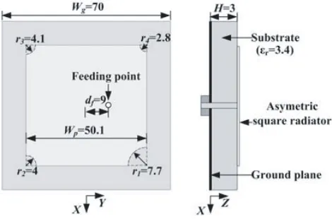
The configuration of the proposed asymmetric microstrip antenna is depicted in Fig. 1. The metal ground plane is placed on the bottom surface of the substrate, which is 70 mm ×70 mm ×3 mm (0.373λ0×0.373λ0×0.016λ0) in size. The square radiator is located at the top surface of the substrate with a width ofWp. Four fan-shaped notches are positioned along the diagonal lines at the four vertexes [(±Wp/2, ±Wp/2)], with different radii of r1, r2, r3 and r4, respectively. A coaxial feed is positioned along the +Y-axis with a distance of df from the center of the radiator. Optimized dimensions of the proposed asymmetric microstrip antenna are listed in Table 1.
Figure 1. Geometry of the proposed antenna (unit: mm).
2.1. Operating Principle of CP Radiation
In this section, the operating principle of CP radiation is presented. A practical way of achieving CP is to trim the ends of two opposite corners of a square patch symmetrically and feed along centerline. By simply exchanging the trimmed-corners with four unequal fan-shaped notches at the four vertexes, the proposed asymmetric microstrip antenna not only generates a CP radiation, but also broadens the 3-dB AR beamwidth. The phenomenon relies on the four unequal fan-shaped notches with the idea of sequentially rotating perturbation [16]. The notches with the gradually smaller radii, approximately circling counterclockwise around the center, correspond to a right-handed circularly polarization (RHCP) pattern and weaken the cross-polarization (right-handed circularly polarization, LHCP) in a wide beamwidth. As a result, the 3-dB AR beamwidth of the proposed patch can be improved. In a similar way, LHCP can be achieved with the same feeding location when the radii of the notches are lessened clockwise. The slight difference is to well maintain the bandwidth of the antenna. Additionally, RHCP/LHCP is also obtained with the feeding point located along theY-axis/X-axis.
(a) (b) (c) (d)
Figure 2. Simulated current distribution on the radiator at 1.575 GHz with different phases. (a) 0◦. (b) 90◦. (c) 180◦. (d) 270◦.
Figure 3. Simulated 3-dB axial ratios (ARs) and gain at 1.575 GHz.
of the conventional corner-truncated patch and the proposed asymmetric patch. In comparison, the proposed antenna can achieve a 3-dB AR beamwidth of 172◦ in the XZ-plane, which is 42◦ wider than the conventional patch. From the simulation results, 3-dB AR beamwidth is over 156◦ as the reference for all plane cuts, and the antenna gain can achieve at least−3.5 dBic. Based on the simulation results, the proposed antenna can have a good performance at low elevation angles for satellite reception.
2.2. Parametric Studies
In order to better comprehend the effect of the unequal fan-shaped notches etched on the square radiator, parametric studies are performed by varying the radii based on the optimized dimensions in this section. When one parameter is studied, the others are kept fixed as shown in Fig. 1.
To obtain RHCP and a wide 3-dB AR beamwidth, the design is guided by the rule that the radii of the notches should be lessened counterclockwise.
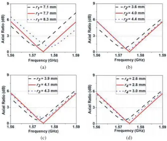
Firstly, the influence of r1 on AR in the direction of the zenith is shown in Fig. 4(a). As r1 is increased, the 3-dB AR operating frequency band is shifted upwards caused by the decreased physical dimension. The desired minimum AR is obtained withr1= 7.7 mm, and the AR becomes worse whether r1 increases or decreases. Because of slightly varyingr1 of 7.7 mm, two orthogonal resonant modes will not be maintained with equal magnitude and 90◦ phase shift, which is the necessary condition for a CP radiation.
Secondly, the effect of the varied r2 on the AR is illustrated in Fig. 4(b) with fixed r1 = 7.7 mm, r3 = 4.1 mm and r4 = 2.8 mm. The minimum AR can be obtained for r2 = 4.0 mm at 1.575 GHz, and AR is deviated minimum value when r2 diverges from 4.0 mm. Parameters r3 and r4 impose their influences on AR in the same manner with r2, as shown in Figs. 4(c)–(d).
(a) (b)
(c) (d)
Figure 4. Simulated axial ratios (ARs) in the direction of the zenith with variations of (a)r1, (b)r2, (c)r3, (d)r4.
r3. In brief, by controlling the radii of the unequal circular notches, two orthogonal modes with equal magnitude and 90◦ phase shift are able to be achieved for CP radiation.
3. CP SEQUENTIAL-ROTATION ARRAY
With the development of personal communication service, the requirement for wideband has increased significantly. Therefore, the application of the proposed asymmetric microstrip antenna is limited due to the narrow bandwidth. Herein, a sequential-rotation array (SRA) is employed for its considerable AR and impedance bandwidth enhancing capability [12, 13].
The CP SRA is composed of four identical asymmetric microstrip antenna elements, which are rotated around a center point in Fig. 5. By using a 1-to-4 probe-to-microstrip feeding network [11], the phases of these elements are set to be 0◦, 90◦, 180◦ and 270◦, respectively. The RHCP can be achieved when the phases increase gradually along the anticlockwise direction. Fig. 6(a) shows that the magnitude difference between the feeding ports, namelyp2 top5, is less than 0.5 dB. It is also observed that the phase difference between the adjacent ports is attained from 75◦ to 102◦ in Fig. 6(b). The simulated results of theS parameters show that the designated feeding network meets the requirement of the CP SRA well.
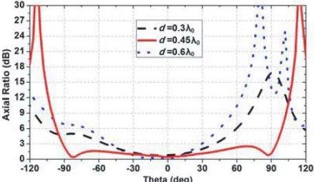
The main step of design is to optimize the distance between two neighboring elements due to its great influence on the 3-dB AR beamwidth. For a wide 3-dB AR beamwidth of the CP SRA, the AR in theXZ-plane is simulated under varied distance d as shown in Fig. 7. Whend= 0.3λ0(λ0is wavelength in the free space at central frequencyf0 = 1.6 GHz), the 3-dB AR beamwidth is approximately 83◦ and 78◦ when d= 0.6λ0. At d= 0.45λ0, the 3-dB AR beamwidth can cover a wide range in the polar axis of −90◦ to +93◦ at 1.6 GHz. Beyond 0.45λ0, the 3-dB AR beamwidth is gradually narrowed. Hence, the valid distancedof the proposed SRA is around 0.45λ0.
Figure 5. Overall configuration of the proposed CP SRA.
(a) (b)
Figure 6. SimulatedS parameters of the feeding network. (a) Magnitude (dB). (b) Phase (deg).
Figure 7. AR with variation of d in the XZ -plane at 1.6 GHz.
Figure 8. Gain-frequency properties for different types of SRAs.
Fig. 8.
Parameters d wp r1 r2 r3 r4
Values 84 mm 50.1 mm 9.5 mm 4.2 mm 3.8 mm 2.8 mm
Parameters εr1 H1 εr2 H2 w1 w2
Values 3.4 3 mm 2.65 0.6 mm 1.2 mm 1.5 mm
Parameters l1 OA AB OC CD W
Values 30 mm 32 mm 32 mm 96 mm 32 mm 170 mm
4. RESULTS
In this section, the overall layout of the designed CP SRA in Fig. 5 is simulated using the ANSYS HFSS and fabricated to verify the predicted results.
(a) (b)
Figure 9. Simulated and measured antenna parameters as a function of frequency. (a)|S11|; (b) Peak RHCP radiation gain and axial ratios (AR).
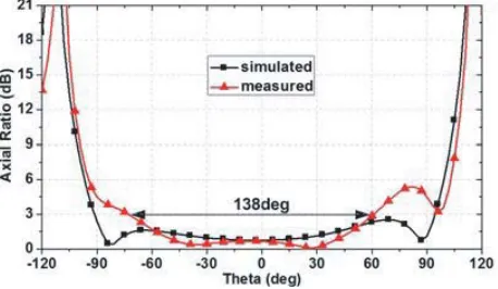
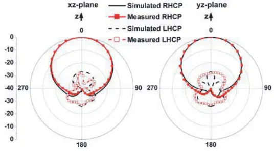
The measured results of |S11|, peak RHCP radiation gain and AR as a function of frequency are compared with the simulated ones in Figs. 9(a) and (b). In the desired band of 1.524–1.648 GHz, we have well achieved the measured results of AR < 3 dB, |S11| < −10 dB and Gain > 10 dBic, which agree well with the simulations. The measured gain variation is less than 1 dB. Fig. 10 depicts the simulated and measured ARs in the XZ-plane at the central frequency 1.6 GHz. The measured 3-dB AR beamwidth reaches 138◦, i.e., −74◦ to 64◦. Fig. 11 shows the simulated and measured radiation patterns at 1.6 GHz. It is noted that the cross-polarization level is less than −27 dB.
Figure 11. Simulated and measured radiation patterns at 1.6 GHz.
5. CONCLUSION
In this paper, a wide-beamwidth circularly polarized (CP) asymmetric microstrip antenna is proposed. Four unequal fan-shaped notches are etched at the vertexes of the square radiator, which make its radiation pattern cover a wide angular range with the beamwidth of about 156◦. The proposed asymmetric microstrip has a 3-dB axial ratio (AR) bandwidth of 1.5%. For wider bandwidth, a circularly polarized sequential-rotation array (SRA) has been proposed, designed and tested. By employing the sequential-rotation feeding network and optimizing the radii of the fan-shaped notches, the 3-dB AR bandwidth is expanded from 1.5% to 7.8% with a good 1-dB gain variation. As shown in both simulation and measurement, a wide-beamwidth of 138◦ is also obtained at the central frequency of 1.6 GHz. Therefore, the proposed SRA can be applied in systems where wide AR bandwidth, wide-beamwidth and small gain variation are needed.
REFERENCES
1. Gao, S., Q. Luo, and F. Zhu, Circularly Polarized Antennas, Wiley-IEEE Press, Hoboken-Piscataway, NJ, USA, Nov. 2013.
2. Wang, R., B. Z. Wang, C. H. Hu, C. Gong, and X. Ding, “Low-profile on-board antenna with a broad beam based on three-current model,” Progress In Electromagnetics Research, Vol. 156, 13–24, 2016.
3. Tan, T., Y. Xia, and Q. Zhu, “A novel wide beamwidth and circularly polarized microstrip antenna loading annular dielectric superstrate with metal ring,” IEEE Antennas and Propagation Society International Symposium, 1883–1884, 2014.
4. Wang, H., X. Wang, S. F. Liu, P. Li, and X. W. Shi, “Broadband circularly polarized antenna with high gain and wide axial ratio beamwidth,” Microw. Opt. Technol. Lett., Vol. 57, No. 2, 377–381, Feb. 2015.
9. Su, C. W., S. K. Huang, and C. H. Lee, “CP microstrip antenna with wide beamwidth for GPS band application,” Electron. Lett., Vol. 43, No. 20, 1062–1063, Sep. 2007.
10. Zhang, C. H., X. L. Liang, X. D. Bai, J. P. Geng, and R. H. Jin, “A broadband dual circularly polarized patch antenna with wide beamwidth,” IEEE Antennas Wireless Propag. Lett., Vol. 13, 1457–1460, 2014.
11. Luo, Y., Q. X. Chu, and L. Zhu, “A low-profile wide-beamwidth circularly-polarized antenna via two pairs of parallel dipoles in a square contour,” IEEE Trans. Antennas Propag., Vol. 63, No. 3, 934–936, Mar. 2015.
12. Yang, S. L. S., R. Chair, A. A. Kishk, K. F. Lee, and K. M. Luk, “Study on sequential feeding networks for subarrays of circularly polarized elliptical dielectric resonator antenna,”IEEE Trans. Antennas Propag., Vol. 55, No. 2, 321–333, Feb. 2007.
13. Rafii, V., J. Nourinia, C. Ghobadi, J. Pourahmadazar, and B. S. Virdee, “Broadband circularly polarized slot antenna array using sequentially rotated technique for C-band applications,” IEEE Antennas Wireless Propag. Lett., Vol. 12, 128–131, 2013.
14. Zhang, J., W. Wu, and D. Fang, “Dual-band and dual-circularly polarized shared-aperture array antennas with single-layer substrate,” IEEE Trans. Antennas Propag., Vol. 64, No. 1, 109–116, Jan. 2016.
15. Zhang, T., W. Hong, and K. Wu, “Analysis and optimum design of sequential-rotation array for gain bandwidth enhancement,”IEEE Trans. Antennas Propag., Vol. 63, No. 1, 142–150, Jan. 2015. 16. Latif, S. I. and L. Shafai, “Hybrid perturbation scheme for wide angle circular polarisation of