Transactions, SMiRT 21, 6-11 November, 2011, New Delhi, India Div-III: Paper ID# 877
1
Structural Integrity Evaluation of the Manbridge Crane at HANARO
Jeong-Soo Ryu1, Shinyoung Kwag1, Young-Ki Kim1
1Research Reactor Engineering Division, Korea Atomic Energy Research Institute (KAERI), Daejeon, KOREA
E-mail of corresponding author: [email protected]
ABSTRACT
The manbridge crane for HANARO has been designed to handle in-pool parts such as fuels, reactor components and reactor utilization facilities of HANARO reactor. To evaluate the structural integrity of the manbridge crane, 3-D finite element models are developed and the dynamic characteristics are analyzed. In addition, the seismic response spectrum analyses of the manbridge crane under the design floor response spectrum loads of OBE and SSE are performed. The analysis results show that the maximum stress values of the manbridge crane for the seismic loads are within the applicable code limits. It is also confirmed that other stress ratios related to the safety of the manbridge crane are less than 1.0. Therefore, any damage on the structural integrity is not expected while the manbridge crane is operating on the top of the reactor and service pool.
KEY WORDS:
HANARO, manbridge crane, seismic analysis, maximum combined stress ratio, modal analysis,structural integrity
INTRODUCTION
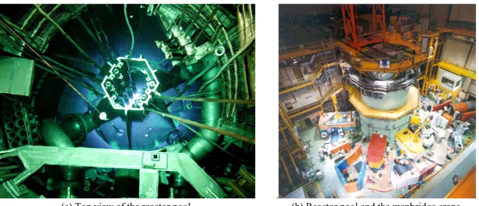
HANARO (Hi-flux Advanced Neutron Application Reactor) is an open-tank-in-pool type research reactor with a maximum thermal power of 30MW. Fig. 1 (a) represents the top view of the HANARO reactor pool. Research and utilization areas of HANARO include four main subjects; radioisotope production, fuel and material irradiation test, neutron beam application, and neutron activation analysis. Research and utilization in these areas are possible by using a proper irradiated object handling system such as crane-type facilities.
.
(a) Top view of the reactor pool (b) Reactor pool and the manbridge crane Fig. 1Reactor pool and the manbridge crane of HANARO
To efficiently handle in-pool parts such as fuels, reactor components and reactor utilization facilities, a manbridge crane has been designed for the purpose of utilizing the HANARO reactor. As shown in Fig. 1 (b), on the top of the reactor and the spent fuel storage pool, in order to allow operators to access to the top of the reactor and fuel storage racks, the manbridge crane is used. The manbridge crane moves from the reactor pool to the spent fuel storage pool along traveling rails and transports the fuel assemblies in the pool by using the fuel tools.
Transactions, SMiRT 21, 6-11 November, 2011, New Delhi, India Div-III: Paper ID# 877
2
carried out for analyzing the dynamic characteristics. Then seismic response analyses and the related safety evaluations are performed for the manbridge crane subjected to seismic loads.
DESIGN OF MANBRIDGE CRANE
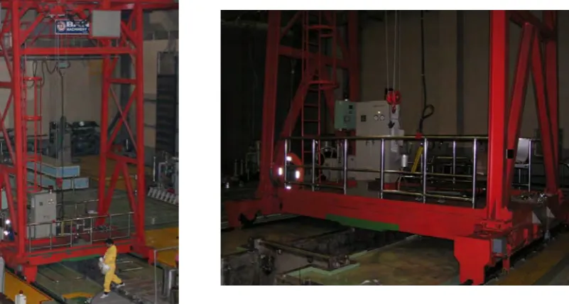
Fig. 2 represents a manbridge crane at HANARO. As shown in Fig. 2, it consists of the traversing rail, the upper deck frame structure, the inspection deck, the vertical frame structures (2EA), the saddle members (2EA), the lower deck frame structure, the walkway, the handrail, the wheel assemblies (4EA) and the trolley. The traversing rail is located in the upper part of the manbridge crane and supported by the upper deck frame structure. The vertical frame structures are composed of x-braces, k-braces and four legs standing in the saddle members. The lower deck frame structure is covered by the walkway with the handrail. The wheel assemblies contain the wheels, seismic lugs and seismic guide rollers which keep the manbridge crane on the traveling rails. The trolley which consists of the hoist and the driving mechanism is hung and traveling on the traversing rail.
(a) Complete manbridge crane (b) Lower parts of the manbridge crane Fig. 2 Manbridge crane
Table 1 summarizes the material properties of the manbridge crane. Most parts of the manbridge crane are made of structural steel (SS41). Stainless steel 304 (S.S 304) is used as the material for the handrail.
Table 1 Material properties of the manbrane structure
Material Structural steel SS41 Stainless steel 304 Young’s modulus (GPa) 203.4 193.1
Density (kg/m3) 7850 7930
Poisson’s ratio 0.3 0.3 Yield strength, Sy(MPa) 248 207
FINITE-ELEMENT MODELING OF MANBRIDGE CRANE
Transactions, SMiRT 21, 6-11 November, 2011, New Delhi, India Div-III: Paper ID# 877
3
distributed masses. The weights of non-structural members such as the walkway, the inspection deck, the traversing rail, the hoist assembly, etc. are modeled as the point masses on the nodes of the beam elements.
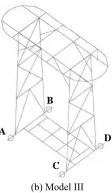
In order to consider a case where the structure is severely challenged during the operation of the manbridge crane, it is developed into five structural models according to the trolley location on the traversing rail and whether the rated load is available or not. As shown in Fig. 3 (a), the trolley is placed in the middle of the straight part of the traversing rail and the rated load is included at the Model I. Model II is similar to Model I but does not consider the rated load. In Model III, the trolley is located at the end of the straight part of the traversing rail and the rated load is included as shown in Fig. 3 (b). Model IV is similar to Model III but does not consider the rated load. In Model V, the trolley is placed in the middle of the curved part of the traversing rail and the rated load is not included. Table 2 summarizes the conditions of the finite element model of the manbridge crane.
Boundary conditions at four wheel assemblies of the manbridge crane are reasonably defined in terms of ASME NOG-1 [2]. Table 3 represents the above boundary conditions.
(a) Model I (b) Model III
Fig. 3 Finite element model of the manbridge crane
Table 2 conditions of the finite element model of the manbridge crane
Model Trolley location on the traversing rail Rated load
I Middle of the straight part O
II Middle of the straight part X
III End of the straight part O
IV End of the straight part X
V Middle of the curved part O
*O : the rated load is available. X : the rated load is not available.
Table 3 Boundary conditions at four wheel assemblies of the manbridge crane
Node Translational motion Rotational motion Ux Uy Uz Rx Ry Rz A Fixed Fixed Fixed
All nodes are considered to be free to rotate.
B Fixed Free Fixed C Free Fixed Fixed D Free Free Fixed A
B
C
D A
B
Transactions, SMiRT 21, 6-11 November, 2011, New Delhi, India Div-III: Paper ID# 877
4
MODAL ANALYSIS
In order to investigate the dynamic characteristics of the manbridge crane, modal analyses of the developed finite element models are performed. The typical measure of the dynamic characteristics, natural frequencies and mode shapes, are obtained by utilizing the ALGOR-Super Sap program.
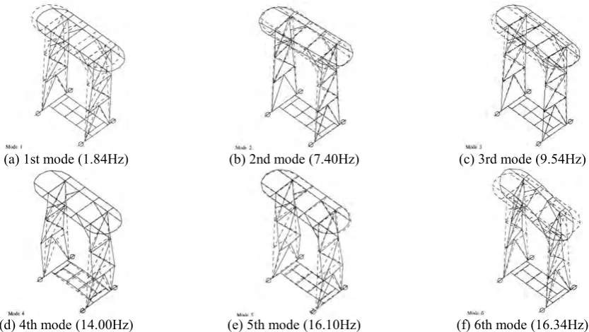
Natural frequencies about Model I, II, III, IV and V according to the trolley location on the traversing rail and the presence of the rated load are obtained. Fig. 4 shows six mode shapes in Model V. Table 4 summarizes the natural frequencies of all models of the manbridge crane. In the case of the Model I and Model III considering the rated load, it can be observed that first and second natural frequencies are 0.44 ~ 0.50 Hz which are lower than those of other modes as these are related to the pendulum effect of the rated load. Except for the first and the second modes of the Model I and III, mode shapes of each model are similar to each other. It means that the structurally fundamental vibration mode of each model is in 1.84Hz ~1.86Hz except for the local pendulum effect of the rated load.
(a) 1st mode (1.84Hz) (b) 2nd mode (7.40Hz) (c) 3rd mode (9.54Hz)
(d) 4th mode (14.00Hz) (e) 5th mode (16.10Hz) (f) 6th mode (16.34Hz) Fig. 4 Natural frequencies and mode shapes of the Model V of the manbridge crane
Table 4 Natural frequencies of the manbridge crane
Model Natural frequency (Hz)
1st 2nd 3rd 4th 5th 6th
I 0.44 0.49 1.86 8.10 9.10 14.00 II 1.84 8.11 9.16 14.01 16.02 16.35 III 0.49 0.50 1.86 7.86 9.37 14.00 IV 1.84 7.90 9.41 14.01 15.83 16.21 V 1.84 7.40 9.54 14.00 16.10 16.34
SEISMIC ANALYSIS OF MANBRIDGE CRANE
The manbridge crane is classified as non-nuclear safety (NNS), seismic category II, and quality class T. For the conservative evaluation of the structural integrity of the manbridge crane, the seismic response analysis, which is applied to the seismic category I structure, is performed. 3-D finite element models of the manbridge crane are developed by utilizing the ALGOR-Super Sap program. Then, the seismic response analyses of the developed 3-D models are carried out.
Transactions, SMiRT 21, 6-11 November, 2011, New Delhi, India Div-III: Paper ID# 877
5
structures as it reduces the computation time in comparison to other methods. In total, 35 modes are considered for the modal response combination to take into account a modal effective mass of 90% of the model, and the square root of the sum of the squares (SRSS) method is used to combine the total response in each direction [3].
Load Combinations and Seismic Loads
According to the CMAA 70 and AISC N690 code [4~5], three loading conditions (Table 5) are used as the load inputs for the structural integrity evaluation of the manbridge crane.
(a) Dead load
All components constituting the manbridge crane and equipment for the operation are considered for the calculation of the dead load.
(b) Live load
The concentrated load such as the trolley weight and the rated load is considered as a live load. It is acting on the location which generates the maximum bending moment and shear force.
(c) Seismic load
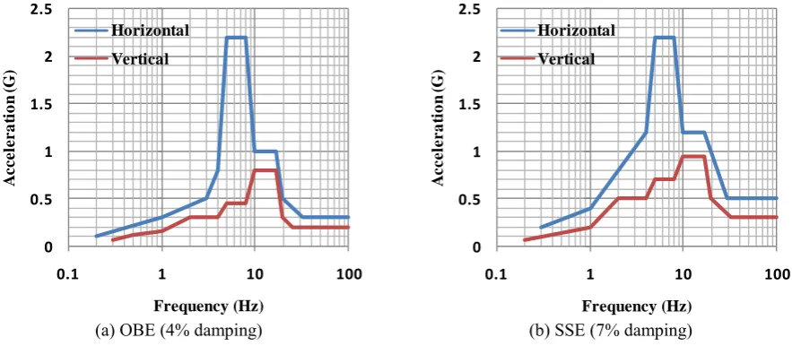
The enveloped floor response spectra for OBE and SSE at the installing position of the manbridge crane, as shown in Fig. 5, are used as the seismic load inputs. According to US NRC Regulatory Guide 1.61 [6], damping 7% and 4% are used for the horizontal and vertical floor response spectrum, SSE and OBE, respectively.
Table 5 Seismic loading conditions used for the seismic analysis of the manbridge crane
Level Load combination Allowable limits
1 Dead load + Live load = S s < 0.60Sy
2 Dead load (+ Live load) + OBE = 1.33S s < 0.80Sy
3 Dead load + SSE = 1.6S s < 0.96Sy
*S: combined strength, s: computed stress, OBE: Operating Basis Earthquake, SSE: Safe Shutdown Earthquake
0 0.5 1 1.5 2 2.5
0.1 1 10 100
A c c e le r a ti o n ( G ) Frequency (Hz) Horizontal Vertical 0 0.5 1 1.5 2 2.5
0.1 1 10 100
A c c e le r a ti o n ( G ) Frequency (Hz) Horizontal Vertical
(a) OBE (4% damping) (b) SSE (7% damping) Fig. 5 Floor response spectrum for OBE and SSE at the installing position of the manbridge crane
Evaluation of the Structural Integrity
For estimating the structural integrity of the beam elements of the manbridge crane in accordance with CMAA codes [3], following conditions are applied.
(a) Allowable stress (fa : allowable normal stress and fv: allowable shear stress in static condition)
Transactions, SMiRT 21, 6-11 November, 2011, New Delhi, India Div-III: Paper ID# 877
6
fv = 0.35Sy (2)
(b) Allowable combined stress
S = (σx2+ 3τxy2)1/2< αSy (3)
where σx denotes normal stress calculated by axial force and bending moment. τxy denotes shear stress generated by
shear force and torsional moment. α are factors related to load combinations. (0.6 for static, 0.8 for static and OBE, 0.96 for static and SSE)
To check the safety against the buckling in axially loaded and bended members such as k-bracings and x-bracings of the manbridge crane, the following equations are applied.
(σa/fA) +(σbx/fBx)+ (σby/fBy) ≤ 1.0, σa/fA ≤ 0.15 (4)
(σa/fBK) +(σbx/fBx)+ (σby/fBy) ≤ 1.0 (5)
where σa denotes the computed axial stress. fA denotes the allowable axial stress that will be permitted if axial force
alone existed. σbx andσby are the computed compressive bending stress at the point consideration in the x and y direction.
fBx andfBy are the allowable compressive bending stress that will be permitted if bending moment alone existed.fBK
denotes the allowable compression stress.
Seismic Analysis Results
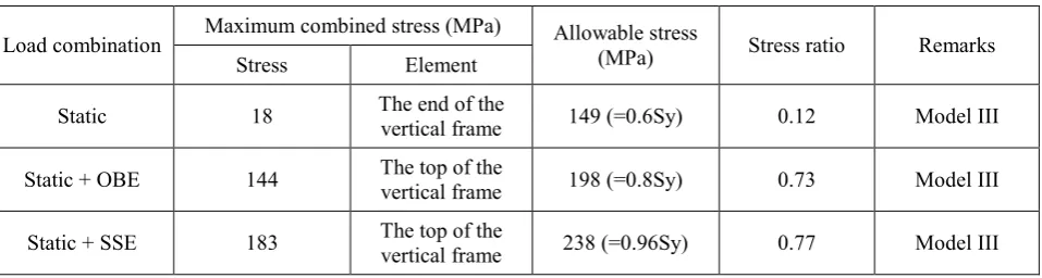
Axial, shear, and combined stresses of each manbridge crane element are estimated. Then, the maximum combined stresses of the manbridge crane are obtained. Model I, II, III, IV and V are considered in the seismic response analyses. The results show that an extreme case is made in the vertical frame structure of the Model III and maximum combined stresses of the manbridge crane are summarized in Table 6. In the case of the safety analyses against the buckling of the k-bracings and x-bracings, the effects of static analyses are not considered since these are negligibly compared to the seismic effects. Maximum stress ratio results on the buckling of the braces subjected to axial load and bending moment are shown in Table 7.
Table 6 Maximum combined stress on the manbridge crane
Load combination Maximum combined stress (MPa) Allowable stress (MPa) Stress ratio Remarks Stress Element
Static 18 The end of the vertical frame 149 (=0.6Sy) 0.12 Model III
Static + OBE 144 The top of the vertical frame 198 (=0.8Sy) 0.73 Model III
Static + SSE 183 The top of the vertical frame 238 (=0.96Sy) 0.77 Model III
Table 7 Maximum stress ratios about the buckling of the braces subjected to axial load and bending moment
Load combination Axial and bending stress (MPa) stress ratio Maximum Remarks
σa σbx σby Element
OBE 20 39 7 The upper part of the x-bracing 0.40 Model I
SSE 21 57 7 The upper part of the x-bracing 0.44 Model V
Transactions, SMiRT 21, 6-11 November, 2011, New Delhi, India Div-III: Paper ID# 877
7
OTHER SAFETY EVALUATION
Safety evaluation of the seismic lug by the maximum uplift force
Maximum uplift force in the wheel assembly of the saddle member takes place when the Model V where the trolley is in the middle of the curve part of the traversing rail and the rated load is not included is under static and SSE load. Maximum uplift force generates maximum stresses in the seismic lug of the wheel assembly. The results are shown in Table 8. From this result, the seismic lug is structurally safe in that the maximum stresses are lower than the allowable stresses.
Table 8 Maximum stresses of the seismic lug by the maximum uplift force
Load
combination Maximum uplift force (kN) Shear stress (MPa) Normal stress (MPa) Allowable shear stress (MPa) Allowable normal stress (MPa)
Static + OBE 60.15 75.19 170.55 115 (=0.46Sy) 198 (=0.80Sy)
Static + SSE 68.83 86.04 195.15 138 (=0.56Sy) 238 (=0.96Sy)
Safety evaluation of the seismic guide roller by the maximum derailment force
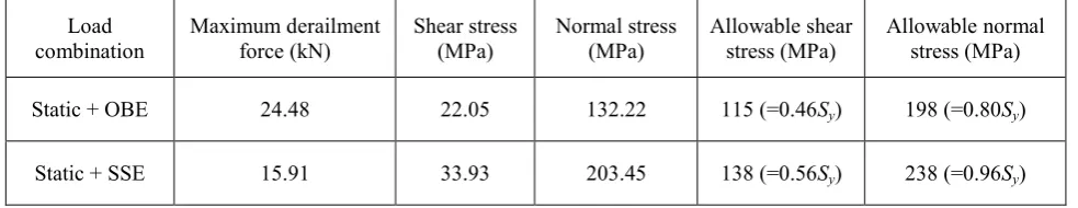
Maximum derailment force acting perpendicularly to the driving direction of the wheel assembly on the saddle member takes place when the Model III where the trolley is at the end of the straight part of the traversing rail and the rated load is included is under static and SSE load. Maximum derailment force generates the maximum stresses in the seismic guide roller of the wheel assembly. The results are shown in Table 9. From this result, the seismic guide roller is structurally safe in that the maximum stresses are lower than the allowable stresses.
Table 9 Maximum stresses of the seismic guide roller by the maximum derailment force
Load
combination Maximum derailment force (kN) Shear stress (MPa) Normal stress (MPa) Allowable shear stress (MPa) Allowable normal stress (MPa)
Static + OBE 24.48 22.05 132.22 115 (=0.46Sy) 198 (=0.80Sy)
Static + SSE 15.91 33.93 203.45 138 (=0.56Sy) 238 (=0.96Sy)
Safety evaluation of the anchor bolts and the concrete
According to the ACI 349 [7], the maximum allowable tension force of the concrete supporting the anchor bolts is 876.12kN (=4Φ(fck)1/2Aeff; Φ : 0.85, fck : design basis strength of the concrete, Aeff: projected concrete failure area of an
anchor). The maximum allowable tension force of the anchor bolt is 132.9kN (=0.9SyAanchor), and the maximum
allowable shear force of the anchor bolt is 55.8kN (=0.56·0.9SyAanchor) in the SSE condition and 45.9kN (=0.46· 0.9SyAanchor) in the OBE condition. Compared to these limits with the maximum values in Table 8 and Table 9, the
anchor bolts and the concrete supporting the anchor bolts are structurally sound because the maximum uplift force and the maximum derailment force are within the allowable limit values.
CONCLUSIONS
Transactions, SMiRT 21, 6-11 November, 2011, New Delhi, India Div-III: Paper ID# 877
8
manbridge crane has been successfully operating and well being used on the top of the pool at the HANARO.
ACKNOWLEDGEMENTS
The authors acknowledge the financial support provided by the Ministry of Education, Science and Technology (MEST) of Korea.
REFERENCES
1. SuperSap Processor Reference Manuel, Algor Interactive System, USA, 1989.
2. ANSI/ASME NOG-1, Rules for Construction of Overhead and Gantry Cranes, Section 4000, 1983.
3. US NRC Regulatory Guide 1.92, Combining Modal Responses and Spatial Components in Seismic Response Analysis, Rev.2, 2006.
4. CMAA 70, Specifications for Top Running Bridge and Gantry Type Multiple Girder Electric Overhead Traveling Cranes, 1994.
5. ANSI/AISC N690, Specification for Safety-Related Steel Structures for Nuclear Facilities, 1994.