IJEDR1402150
International Journal of Engineering Development and Research (www.ijedr.org)2214
Temperature Distribution Analysis of MgZrO
3
Coated
and Conventional IC Engine Components using FEM
1 Vikram A. Mistry, 2 Dipak C. Gosai, 3 Dr. H.J. Nagarsheth 1 Research Scholars, 2 Associate Professor, 3 Head of Department
1
IC Engine and Automobile,
1Shree S'ad Vidya Mandal Institute of Technology, Bharuch-392001, Gujarat, INDIA,
,
1[email protected],2[email protected],3[email protected]
________________________________________________________________________________________________________
Abstract— since the invention of automobile, man began to deal with high efficient system by low heat rejection and
utilizing the heat for further operation. With the shortage of fuel, this problem got major attention to the researchers. The main idea was to effective utilization of heat obtained from combustion of fuel and to decrease heat loss from combustion chamber so it is utilized in power stroke. This paper deals with temperature distribution analysis of the conventional (uncoated) and ceramic material coated IC engine combustion chamber components. In this study, firstly, thermal analyses are investigated on a conventional (uncoated) diesel piston and cylinder head, made of aluminum silicon alloy and cast iron respectively. Secondly, thermal analyses are performed on pistons and cylinder head, coated with ceramic material MgZrO3 by means of using a commercial code, namely ANSYS. After that, the results of ceramic coated
components are compared with conventional one. The effect of coating on thermal behaviors of components are investigated. In which noted that the maximum surface temperature of the coated piston and cylinder head is increased about 479.4 0C and 108.6 0C respectively.
Index Terms—Thermal barrier coatings,MgZrO3, Temperature distribution, Finite Element Method
________________________________________________________________________________________________________
I.INTRODUCTION
The automobile industry is facing a serious challenge to improve vehicle fuel efficiency. Global demand for cars is soaring - one forecast has the number of worldwide cars increasing five-fold by 2050 to 2.9 billion. In the scenario of increase of vehicle population at an alarming rate due to advancement of civilization, use of diesel fuel in not only transport sector but also in agriculture sector is leading to fast depletion of diesel fuels and increase of pollution levels with these fuels, efficient fuel utilization has become pertinent for the engine manufacturers, users and researchers involved in the combustion research. While search for alternate fuels continuing, researchers are also attempting to find different techniques of efficient fuel utilized in diesel engines [1].
Reductions in fuel consumption can be achieved by a variety of measures, including improved aerodynamics, weight reductions and hybrid power trains. Significant improvements must also be made to the efficiency of the internal combustion (IC) engine that powers nearly all the world's vehicles. One promising technology for improving IC engine efficiency, as well as performance and durability, is the Thermal Barrier Coating (TBC) [1]. Applying TBC on conventional engine means converting engine into Low Heat Rejection engine (LHRE).
II.THERMAL BARRIER COATINGS
Thermal barrier coatings are duplex systems, consisting of a ceramic topcoat and a metallic intermediate bond coat. The topcoat consists of ceramic material whose function is to reduce the temperature of the underlying, less heat resistant metal part. The bond coat is designed to protect the metallic substrate from oxidation and corrosion and promote the ceramic topcoat adherence. A thermal barrier application is shown in figure 1
Fig. 1 Thermal barrier coating consisting of metallic bond coat on the substrate and ceramic top coat on the bond coat[3].
IJEDR1402150
International Journal of Engineering Development and Research (www.ijedr.org)2215
thermal barrier coatings. In figure 2, 1 indicates piston head, 2 indicates cylinder liner, 3 indicates seating of intake valve, 4 indicates seating of exhaust valve, 5 indicates cylinder head, 6 indicates intake valve and 7 indicates exhaust valve.Fig. 2 Potential thermal barrier coated components in a diesel engine combustion chamber[2].
The design of the thermal barrier coatings and the environment in which it operates impose restrictions on the materials of construction.
Properties of different material used for Analysis
Table 1 Thermal properties [4]
Properties Material
AlSi Cast Iron NiCrAl MgZrO3
Density 2700 kg /m3 7150 kg /m3 7870 kg /m3 5600 kg /m3
Coefficient of
Thermal Expansion 2.1e-005 1/
0C 1.255e-005 1/0C 1.2e-005 1/0C 8.e-006 1/0C
Thermal
Conductivity 155 W/m
0C 30.8 W/m0C 16.1 W/m0C 0.8 W/m0C
Specific Heat 960 J/kg0C 460 J/kg0C 764 J/kg0C 650 J/kg0C III.FINITE ELEMENT METHOD
What is FEA?
• Finite Element Analysis is a way to simulate physical loading conditions on a design and determine the design‟s response to
those conditions [15]
• The design is modeled using discrete building blocks called elements. Each element has exact equations that describe how it responds to a certain load. The “sum” of the response of all elements in the model gives the total response of the design. The elements have a finite number of unknowns, hence the name finite elements.
• The finite element model, which has a finite number of unknowns, can only approximate the response of the physical system, which has infinite unknowns.
– So the question arises: How good is the approximation?
– Unfortunately, there is no easy answer to this question. It depends entirely on what is being simulated and the tools that are being used for the simulation.
The following figure shows the physical structure to be analyzed. The physical structure to be analyzed is ladder which is subjected to weight of the applicant. The physical system to be analyzed, then, divided into finite elements and they are connected at the common joints so called “nodal points”. An element is the building block of a finite element model which exactly represents the behavior of the physical structure to be analyzed. Each element has exact equations that describe how it responds to a certain load. The “sum” of the response of all elements in the model gives the total response of the design. The elements have a finite number of unknowns, hence the name finite elements. More the number of elements, greater is the accuracy of the result.
Conversion of Solid model into Finite element model
Finite element method requires finite element model that has element, nodes and it does work on solid model. Therefore solid structure to be analyzed should be converted into finite element model. Finite element model can be obtained by dividing the structure into finite elements and then connecting them together as solid structure is physically continuous. There are variety of element types depending on the type of analysis and physical problem. The element selection has dramatic influence on the result obtained. The type of element and its capability should be very well known to the analyst before carrying out any analysis.
Meshing is the process used to “fill” the solid model with nodes and elements, i.e., to create the FEA model. An element is a
IJEDR1402150
International Journal of Engineering Development and Research (www.ijedr.org)2216
Figure 3 Conversion of solid model into FEA model.Typical finite element method procedure [15]
1. Divide the structure or continuum into finite elements. Mesh generation programs, called preprocessor, help the user in doing this work.
2. Formulate the properties of each element
3. Assemble the elements to obtain the finite element model of the structure.
4. Apply known loads: apply known loads and/or moments in stress analysis, nodal heat fluxes, convection loads in heat transfer.
5. In stress analysis, specify how the structure is supported. This step involves setting several nodal displacements to known values (which often are zero).In heat transfer analyses, where typically certain temperatures are known, impose all known values of nodal temperature.
6. Solve simultaneous linear algebraic equations to determine nodal degree of freedom ( nodal displacements in stress analysis, nodal temperatures in heat transfer)
7. In stress analysis, calculate element strains from the nodal displacements and finally calculate stresses from strains. In heat transfer analysis, calculate element heat fluxes from the nodal temperatures. Output interpretation programs, called post processors, help the user sort the output and display in graphical form.
The power of the finite element method resides principally in its versatility. The method can be applied to various physical problems. The structure can have arbitrary shape, loads, and support conditions. Mesh can mix elements of different types, shapes, and physical properties. This great versatility is contained within a single computer program. User input data controls the selected problem type, geometry, boundary conditions, element selection, and so on. Another attractive feature of finite elements is the close physical resemblance between the actual structure and finite element method. The finite element method also has disadvantages [15]. A specific numerical result is found for a specific problem: A finite element analysis provides no closed form solution that permits analytical study of the effects of changing various parameters. A computer, a reliable program, and intelligent use are essential. Experience and good engineering judgments are needed in order to carry out real analysis [15] .
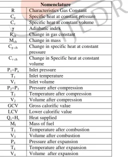
Nomenclature
R Characteristics Gas Constant Cp Specific heat at constant pressure Cv Specific heat at constant volume
γ Adiabatic index Rch Change in gas constant Mch Change in mass
Cpch Change in specific heat at constant pressure
Cv ch Change in Specific heat at constant volume
P1=Pa Inlet pressure T1 Inlet temperature V1 Inlet volume
P2=P3 Pressure after compression T2 Temperature after compression V2 Volume after compression GCV Gross calorific value LCV Lower calorific value Qs=Hs Heat supplied
Mf Mass of fuel
IJEDR1402150
International Journal of Engineering Development and Research (www.ijedr.org)2217
QR=HR Heat rejectedρ Cut off ratio
ηdiesel Efficiency of diesel engine IV.BOUNDARY CONDITION
For boundary condition for calculating different parameter engine specification and calculation given below. ENGINE : Water cooled 4 – stroke twin cylinder direct injection diesel engine Test rig
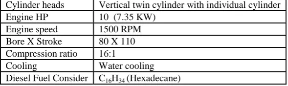
Table 2 Specification of vertical twin cylinder engine
Cylinder heads Vertical twin cylinder with individual cylinder
Engine HP 10 (7.35 KW)
Engine speed 1500 RPM Bore X Stroke 80 X 110 Compression ratio 16:1
Cooling Water cooling
Diesel Fuel Consider C16H34 (Hexadecane)
Engine working on constant pressure cycle ( Diesel Cycle) 1-2 Isentropic Compression
2-3 Addition of heat at constant pressure 3-4 Isentropic Expansion
4-1 Rejection of heat at constant volume
Point 1 represent that the cylinder is full of air. Let P1, V1 and T1 be the corresponding pressure, volume and absolute temperature. The piston then compresses the air adiabatically i.e. PVγ = constant ) till the values become P2, V2 and T2 respectively (at the end of the stroke) at point 2. Heat is then added from a hot body at a constant pressure. During this addition of heat let volume increases from V2 to V3 and temperature T2 to T3, corresponding to point 3. This point is called the point of cut off. The air then expands adiabatically to the condition P4, V4 and T4 respectively corresponding to point 4. Finally, the air rejects the heat to the cold body at constant volume till the point 1 where it returns to its original state.
C16H32 + 24.5(O2+3.762N2) 16CO2 +17H2O + 92.109N2 C16H34 + 24.502 + 92.169 N216CO2 +17H2O +92.109N2 226 + 784 +2580.732 704+306 +2580.732(=3590.732)
Air fuel ratio (A : F) = Mass of air / mass of fuel (A : F) = (784 +2580.732)/226 = 14.888 : 1
Stoichiometric Condition ( Ch = Charge ) Rch = IR/Mch =8314/ Mch
∑moles = ∑mass /∑mol. mass = 117.669 = ∑mol. mass = Mch = 30.51553 kg/kg moles
So Rch = 272.4514 J/kg-K
Table 3 Composition of fuel gas on mass and moles bases
From thermodynamics of equation CP – Cavy = R
Cp ch – Cv ch = Rch CP/ Cv - 1= Rch/ Cv
Constituents Mass Mol. Mass Moles Compositions on
% Mass % Moles
(A). Reactions
C16H34 226 226 1 6.293988 0.84984
O2 784 32 24.5 21.83398 20.82111
N2 2580.732 28 92.169 71.87203 78.32904
∑ mass reactant ∑3590.732 ∑ moles =117.669 ∑100% ∑100% (B). Products
CO2 704 44 16 19.60603 12.78271
H2O 306 18 17 8.52193 13.58163
N2 2580.732 28 92.169 71.87203 73.63564
IJEDR1402150
International Journal of Engineering Development and Research (www.ijedr.org)2218
γ – 1 = 272.4514/ 825γ = 1.3302
At site condition of engine
Atmospheric pressure P1 = Pa = Pbx/Pr = 744/750 = 0.992 bar Suction temperature T1 = 280C
Analysis of engine cycle
(a). during suction from ideal gas equation P1 = Mch. Rch. T1
Assume Mch = 1.00 kg
0.992 x 10⁵ x V1 = 1 x 272.45 x ( 28 + 273 )
V1 = 0.82669 m3 (1) Compression ratio = r = V1/V2= 16 = 0.82669/ V2
V2 = 0.0516682 m 3
(2) (b). 1-2 compression process
P1 V1 γ
= P2 V2 γ
0.992 x 105 x (16)1.3302 = P2 P2 = 39.62700 x 10
5
N/m2 =39.63700 bar (3) P2V2 = MRT2
39.62700 x 105x 0.0516682 = 1 x 272.45 x T2 T2 = 751.5 0K = 478.5 0C
(c) 2-3 Combustion Process at constant Pressure
Stoichiometric complete combustion condition of 1 kg of fuel 1 For complete combustion of carbon
C + O2 CO2
12 kg 32 kg 44kg
0.865 kg + 2.30662 kg 3.1716 kg 0.8650 + (32/12) x 0.8650 (44/12) x 0.865 2 For complete combustion of hydrogen
H2 + 1/2 O2 H2O
2 kg 16 kg 18kg
0.132 kg + 1.056 kg 1.188 kg 3 For complete Combustion of sulpher
S + O2 SO2 32 kg 32 kg 64kg 0.003 kg + 0.003 kg 0.006 kg ∑Pn = nSO2 + nCO2 + nH2O
= 0.006/64 + 3.1716/44 + 0 = 0.0721755 kg moles ∑Rn = nO2Ic + nO2IH + nO2IS = 2.3066/32 + 1.056/32 + 0.003/32 = 0.1051756 kg moles
∆n = ∑Pn - ∑Rn
= 0.0721755 – 0.1051756 = - 0.033000 kg moles GCVC=P = 47269. Kj/kg LCVC=P = 43957 Kj/kg GCVC= P = GCVC=v + ∑∆n.RCH T
47269 = GCVC=v + (-0.033 )x 8.314 x (28+273) GCVC=v = 47351.5829 kj/kg
GCVC=V = LCVC=V +2305.09XMW
47351.5829 = LCVC=V +2305.09(9 X 0.132) LCVC=V = 44613.1359Kj/kg
Mass of fuel = 0.06293980 kg/cycle (4) QS = HS = Mf X LCVC=V
= 0.0629398 X 44613.135 = 2807.94 kj/kg cycle
QS = HS = Mch X CPCh X (T3- T2) 2807.94 = 1 X 1.192 X(T3 – 751.5) T3 = 3107.15 K
IJEDR1402150
International Journal of Engineering Development and Research (www.ijedr.org)2219
2-3 Heat supplied at constant pressureP2V2/T2 = P3V3/T3 0.0516682/751.5 = V3/3107.15 V3 = 0.213651 m3
Rch = IR/Mch
= 8314/ Mch
∑moles = ∑mass /∑mol. mass = 125.169 = 3590.732 /∑mol. mass
∑mol. mass = Mch = 28.68 kg/kg moles Rch = IR/Mch
= 8314/ 28.68 = 289.816 J/kg-K From thermodynamics of equation
CP – Cv = R Cp ch – Cv ch = Rch
CP/ Cv - 1= Rch/ Cv γ – 1 = 289.816/903 γ = 1.321
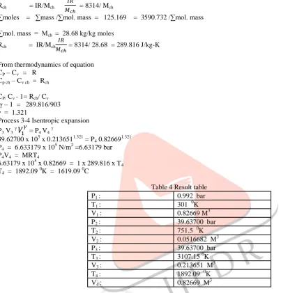
Process 3-4 Isentropic expansion P3 V3γ = P4 V4γ
39.62700 x 105 x 0.2136511.321 = P4 0.82669 1.321
P4 = 6.633179 x 10⁵ N/m2 =6.63179 bar P4V4 = MRT4
6.63179 x 105 x 0.82669 = 1 x 289.816 x T4 T4 = 1892.09
0
K = 1619.09 0C
Table 4 Result table
P1 : 0.992 bar
T1 : 301
0 K
V1 : 0.82669 M3
P2 : 39.63700 bar
T2 : 751.5 0K
V2 : 0.0516682 M
3
P3 : 39.63700 bar
T3 : 3107.15 0K
V3 : 0.213651 M3
T4 : 1892.09 0K
V4 : 0.82669 M3
The instant gas temperature values were calculated according to measured gas pressure in combustion chamber and Woschni formula as followed was employed in this work to obtain the instant CoHT. [12]
hg = 453.6D-0.214 (CmPg)0.786Tg-0.525 (5)
where hg was defined as instant CoHT of gas at piston top surface, D diameter of cylinder, Cm average velocity of piston, Pg instant gas pressure and Tg instant gas temperature which could be obtained from following equations.
Here hg is calculated for peak condition at point 3
Tg = PgVx/(mR) (6)
Vx = Vc+ πD 2
Sx/4 (7)
Sx = S[1- cos φ + 1/λ {1-(1- λ2 sin2 φ)1/2}]/2 (8)
IJEDR1402150
International Journal of Engineering Development and Research (www.ijedr.org)2220
In this case crank radius r = 55 mm connecting rod length l = 258.5 mm and crank angle φ = 300 after TDC[12]By putting this value in equation (8)
Sx = 16.760 mm
by using equation (7)
Vx = Vc+ πD2Sx/4
= 0.0516682 + π (0.08)2 (0.016760)/4
= 0.0516893 m3
By putting value of maximum gas pressure Pg = 39.63700 (from equation 3) and value of m from equation (4) in equation (6)
we get, Tg = 2835.53 0C
velocity of piston Cm = ωr
ω= 2πN/60 =2π(1500)/60 = 160.64 rad/s Cm = (160.64)(0.055) = 8.8352 m/s
For heat transfer coefficoent
hg = 453.6D -0.214
(CmPg) 0.786
Tg -0.525
by putting above values in this equation we get,
hg = 5100.14 W/m20C
So Boundary conditions for convections are
hg = 5100.14 W/m20C Tg = 2835.53 0C
According to author experience And bottom temp 2410C [16]
Boundary conditions for cylinder head For inside condition
hg = 5100.14 W/m 20
C
Tg = 2835.53 0C it is same as in case of piston
And top surface temperature is read by using K-type thermocouple which have a range of about -200 to 1100 0C and error of +/-1 0
C is 410C
V.FEM ANALYSIS USING ANSYS Assumption used in analysis
Metal piston is made of Al-Si alloy. Piston alloy and coating are isotropic and linearly elastic. Convection coefficients and temperatures of surroundings at bottom and side piston surfaces are constant throughout the cycle. The contact between successive layers of material is tight.
The heat is applied on the piston through a certain portion which is inside the cylinder. But it assumed that the heat is falling on the piston only and no other part is coming in contact with cylinder gas.
Load on the piston is not uniform on its surface but it is considered same heat load over entire surface of piston.
The piston is surrounded by the oil layer and then the solid part of of the engine. Then the heat is removed by water flowing through the cylinder body. But during the analysis, the resistance of oil film and solid part of cylinder is considered negligible.
Piston was motionless, the effect of gas forces is omitted.
The temperature distribution in the piston through its body varies in the piston itself as measured practically but it is considered that temperature is same radially at all location but can be varied along its length.
Results and their physical interpretation Standard (Conventional) piston
IJEDR1402150
International Journal of Engineering Development and Research (www.ijedr.org)2221
Figure 4 Temperature distributions of the piston made up of aluminum silicon.Maximum temperature achieved is 2495.8 0C Minimum temperature achieved is 241 0C
Temperature at 350 µm from top surface of piston is 2420.3 0C Temperature at 500 µm from top surface of piston is 2414.5 0C
Binder material-NiCrAl of 150 µm and Coating material-MgZrO3 of 350 µm
Coated piston consist of 150 µm thickness binder of NiCrAl and 350 µm thickness of MgZrO3 coating.
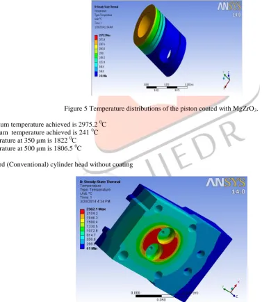
Figure 5 Temperature distributions of the piston coated with MgZrO3.
Maximum temperature achieved is 2975.2 0C Minimum temperature achieved is 241 0C Temperature at 350 µm is 1822 0C Temperature at 500 µm is 1806.5 0C
Standard (Conventional) cylinder head without coating
Figure 6 Temperature distributions of the cylinder Head made up of cast iron.
IJEDR1402150
International Journal of Engineering Development and Research (www.ijedr.org)2222
Temperature at 350 µm from top surface of piston is 1960 0CTemperature at 500 µm from top surface of piston is 1933.3 0C
Binder material-NiCrAl of 150 µm and Coating material-MgZrO3 of 350 µm
Figure 7 Temperature distributions of the cylinder head coated with MgZrO3
Maximum temperature achieved is 2470.7 0C Minimum temperature achieved is 41 0C Temperature at 350 µm is 1282.7 0C Temperature at 500 µm is 1251.1 0C
Temperature distribution analysis is carried out using ANSYS software on diesel engine combustion chamber components are shown in Fig 4 to Fig 7. In which comparison of conventional engine piston, cylinder head and MgZrO3 coated piston, cylinder head are shown.
Fig 4 shows the temperature distribution analysis of conventional piston without coating in which different temperature are shown. Secondly, temperature distribution is carried out on MgZrO3 coated piston as shown in fig 5.
Temperature on conventional piston at top surface is maximum temperature i.e. 2495.8 0C, temperature at 350 µm from top surface of piston is 2420.3 0C and temperature at 500 µm from top surface of piston is 2414.5 0C. For MgZrO3 coated piston these temperatures are 2975.2 0C, 1822 0C and 1806.5 0C respectively. So increase in surface temperature is 479.4 0C i.e. 19.21%.Decrease in temperature at 350 µm from top surface of piston is 598.3 0C i.e. 24.72%. Decrease in temperature at 500 µm from top surface of piston is 608 0C i.e. 25.18%.
Temperature on conventional cylinder head at top surface as shown in fig 6 is maximum temperature i.e. 2362.1 0C, temperature at 350 µm from top surface of cylinder head is 1960 0C and temperature at 500 µm from top surface of cylinder head is 1933.3 0C. From fig 7 MgZrO3 coated cylinder head these temperatures are 2470.7 0C, 1282.7 0C and 1251.1 0C respectively. So increase in surface temperature is 108.6 0C i.e. 4.6 %. Decrease in temperature at 350 µm from top surface of cylinder head is 677.3 0C i.e. 34.56 %. Decrease in temperature at 500 µm from top surface of cylinder head is 682.2 0C i.e. 35.29%.
So the surface temperature increases and transferring less heat to base piston metal. So combustion temperature increases and heat transfer through the engine parts is minimized by applying the thermal barrier coating materials on the top surface of the engine piston and cylinder head. So this heat energy is used in shaft work so efficiency of engine is increases.
VI.CONCLUSIONS
It can be concluded that in a LHR engine i.e. MgZrO3 coated engine, less amount of heat is rejected to the atmosphere because of the presence of a low thermal conductivity ceramic coating which almost reduces the heat loss to the atmosphere and to the cooling jackets.
It is concluded that increase in surface temperature of piston is. 19.21%, decrease in temperature at 350 µm from top surface of piston is 24.72%.and decrease in temperature at 500 µm from top surface of piston is 25.18%.
In Case of Cylinder head increase in surface temperature is 4.6 %.,decrease in temperature at 350 µm from top surface of cylinder head is 34.56 % and decrease in temperature at 500 µm from top surface of cylinder head is 35.29%.
VII.ACKNOWLEDGEMENT
The author would like to thank SVMIT Mechanical engineering department, Bharuch for their valuable input during course of investigation.
REFERENCES
IJEDR1402150
International Journal of Engineering Development and Research (www.ijedr.org)2223
[2] Ilker Turgut, Yilmaz Metin, Gumus Mehmet Akçay "Thermal Barrier Coatings For Diesel Engines" InternationalScientific Conference 19 – 20 November 2010, Gabrovo
[3] M. Cerit, V. Ayhan, A. Parlak, H. Yasar " Thermal Analysis Of A Partially Ceramic Coated Piston: Effect On Cold Start Hc Emission In A Spark Ignition Engine"Applied Thermal Engineering 31 (2011) 336e341
[4] Ekrem Buyukkaya, Muhammet Cerit "Thermal Analysis Of A Ceramic Coating Diesel Engine Piston Using 3-D Finite Element Method" Surface & Coatings Technology 202 (2007) 398–402
[5] J.Rajasekaran, B.M.Gnanasekaran, T.Senthilkumar, B.Kumaragurubaran, M.Chandrasekar "Effect Of Thermal Barrier Coating For The Improvement Of Si Engine Performance & Emission Characteristics" International Journal Of Research In Engineering And Technology Eissn: 2319-1163 | Pissn: 2321-7308 Volume: 02 Issue: 07 | Jul-2013
[6] Ahmet Okur1, Recep Yigit1, Erdal Celik2 and Onur Sayman3 "THERMAL STRESS ANALYSIS IN ZrO2 INSULATION COATINGS ONCr-Ni SUBSTRATES DURING COOLING PROCESS" Mathematical and Computational Applications, Vol. 16, No. 3, pp. 598-604, 2011.
[7] Callister, W.D. “Materials science and engineering –An introduction,” 6th Ed., John Wiley and Sons (Asia) Pte.Ltd, Singapore, 2004.
[8] Murat Ciniviz " Performance And Energy Balance Of A Low Heat Rejection Diesel Engine Operated With Diesel Fuel And Ethanol Blend" 2009 No. 09-Csme-33, E.I.C. Accession 3119
[9] Pradeep Kumar A.R, Annamalai K., Prabhakar S., Banugopan V.N., Premkartikkumar S.R "Heat Transfer Analysis In A Low Heat Rejection Di Diesel Engine" National Journal On Advances In Building Sciences And Mechanics, Vol. 1, No.2, October 2010
[10] M Azadi, M. Baloo, G. H. Farrahi, S. M. Mirsalim "A Review Of Thermal Barrier Coating Effects On Diesel Engine Performance And Components Lifetime" International Journal Of Automotive Engineering Vol. 3, Number 1, March 2013
[11] MAHDI HAMZEHEI MANOCHEHR RASHIDI "Determination of Piston and Cylinder Head Temperature Distribution in a 4-Cylinder Gasoline Engine at Actual Process" Proceedings of the 4th WSEAS Int. Conf. on HEAT TRANSFER, THERMAL ENGINEERING and ENVIRONMENT, Elounda, Greece, August 21-23, 2006 (pp153-158)
[12] Xiqun Lu a,*, Quan Li b, Wenping Zhang a, Yibin Guo a, Tao He a, Dequan Zou a "Thermal analysis on piston of marine diesel engine" a College of Power and Energy Engineering, Harbin Engineering University, Harbin, Heilongjiang Province 150001, China 10 June 2012
[13] Gudimetal P.& Gopinath C.V "Finite Element Analysis of Reverse Engineered Internal Combustion Engine Piston"
AIJSTPME (2009) 2(4): 85-92
[14] Thet T. Mon, Rizalman Mamat, Nazri Kamsah, Member, IAENG "Thermal analysis SI engine using simplified Finite Element model" Proceedings of the World Congress on Engineering 2011 Vol III WCE 2011, July 6 - 8, 2011, London, U.K.
[15] Cook R.D., D.S.Malkus; and M.E.Plesha. Concepts and Applications of Finite Element Analysis, 3rd ed., New York: Wiley, 1989.
[16] BOHAC, S. V., Baker, D. M. and Assanis, D. N. A Global Model for Steady State and Transient S.I. Engine Heat Transfer Studies. SAE Paper 960073, 1996.
[17] Special Report: The art of the possible. Economist, http://www. economist.com/node/12544947, 2008.
[18] Yogesh Jaluria, [email protected] "Simulation-Based Optimization Of Thermal Systems" Department Of Mechanical And Aerospace Engineering Rutgers, The State University Of New Jersey New Brunswick, Nj 08903, Usa [19] Sofia A. Tsipas,(2005) „Thermophysical Properties of Plasma Sprayed Thermal Barrier Coatings‟ thesis of University Of
Cambridge, Department of Materials Science and Metallurgy.
[20] Miyairi, Y., “Computer simulation of an LHR direct injection diesel engine” SAE Paper No. 880187, 1988.
![Fig. 2 Potential thermal barrier coated components in a diesel engine combustion chamber[2]](https://thumb-us.123doks.com/thumbv2/123dok_us/8507338.1392825/2.595.51.539.299.448/potential-thermal-barrier-coated-components-diesel-combustion-chamber.webp)