MERLIN LEGEND
COMMUNICATIONS SYSTEM
Notice
Every effort was made to ensure that the information in this book was complete and accurate at the time of printing. However, information is subject to change.
Federal Communications Commission (FCC) Information
For important FCC interference, registration, and repair information, see "Customer Support Information" in this book.
Trademarks
Accunet is a registered trademark of AT&T. Magic on Hold is a registered trademark of AT&T. Megacom is a registered trademark of AT&T. MERLIN is a registered trademark of AT&T. MERLIN LEGEND is a trademark of AT&T. MERLIN MAIL is a trademark of AT&T.
MLX-10, MLX-10D, MLX-20L, and MLX-28D are trademarks of AT&T. MultiQUEST is a registered trademark of AT&T.
Support Telephone Number
Customer Support Information
vii■ Support Telephone Number vii
■ FCC/DOC Information vii
■ Security xi
■ Warranty xi
About This Book
xiii■ Related Documentation xiv
■ How to Order Books xiv
■ Additional Ordering Information xv
■ Product Safety Labels xv
■ How to Comment on This Book xv
1
Data Communications with This System
1-1■ Data Communications Overview 1-1
■ Data Stations 1-3
■ System Features Used for Data 1-4
■ Data Communications Components 1-5
2
Data Communications Hardware
2-1■ ISDN 7500B Data Module 2-1
■ Modems 2-5
■ Modem Pools 2-7
■ Hardware Decision Flowcharts 2-12
3
Planning
3-1■ Planning Overview 3-1
■ Forms 3-2
■ Station Jacks 3-4
■ Modem Pools 3-8
■ Assigning Lines to Data Stations 3-12
■ Assigning Features to Data Stations 3-17
■ Data Hunt Groups 3-22
4
System Programming
4-1■ Preparation and Forms 4-1
■ Programming Instructions 4-3
5
Making and Receiving Data Calls
5-1■ Calling with Analog Data Equipment 5-2
■ Calling with Digital Data Equipment 5-7
■ System Data Features 5-11
A
Data Forms
A-1A B B
Abbreviations
ABB-1G L
Glossary
GL-1IN
Index
IN-11
Data Communications with This System
1-11-1 Individual Use Data Station Configurations 1-6
1-2 Modem Pools Assigned to Data Hunt Groups 1-8
1-3 Data Stations Connected to Local Host Computer and LAN Workstation 1-10
1-4 Outside Lines/Trunks 1-12
2
Data Communications Hardware
2-22-1 ISDN 7500B Data Module Front Panel 2-2
2-2 ISDN 7500B Data Module Back Panel 2-2
2-3 Asynchronous Hardware Decision Flowcharts 2-13
2-4 Synchronous Hardware Decision Flowcharts 2-14
3
Planning
3-13-1 Modem Pools Using System Lines 3-8
3-2 Modem Pools on Dedicated Outside Lines 3-9
3-3 Data Hunt Groups 3-23
2
Data Communications Hardware
2-12-1 Data Module Settings for Digital-to-Analog Pool 2-8
2-2 Modem Option Settings for Digital-to-Analog Modem Pool 2-9 2-3 Data Module Settings for Analog-to-Digital Modem Pool 2-10
2-4 Modem Settings for Analog-to-Digital Modem Pool 2-10
3
Planning
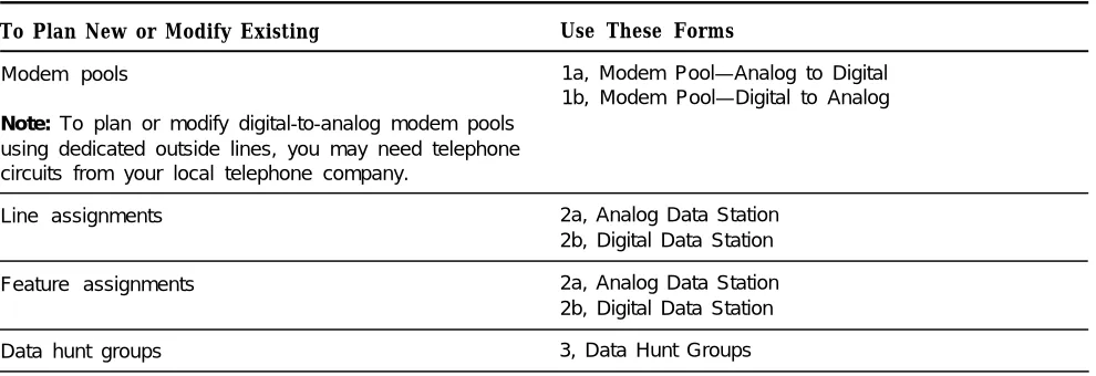
3-13-1 Data Planning Forms 3-2
3-2 Key or PBX System Forms 3-3
3-3 Station Jack Types 3-4
4
System Programming
4-14-1 Planning Forms 4-2
5
Making and Receiving Data Calls
5-15-1 Call Progress Messages 5-8
5-2 Data Station Features 5-11
completion of an AT&T hands-on instructor-led course covering installation and maintenance for this product. Installation or maintenance of this product by anyone other than a qualified service technician may void the warranty. Hazardous electrical voltages are present inside this product.
The exclamation point in an equilateral triangle is intended to alert the user to the presence of important operating and maintenance (servicing) instructions in the literature accompanying the product.
IMPORTANT SAFETY INSTRUCTIONS
When installing telephone equipment, basic safety precautions should always be followed to reduce the risk of fire, electric shock, and injury to persons, including:
Read and understand all instructions.
Follow all warnings and instructions marked on or packed with the product. Never install telephone wiring during a lightning storm.
Never install telephone jacks in a wet location unless the jack is specifically designed for wet locations.
Never touch uninsulated telephone wires or terminals unless the telephone wiring has been disconnected at the network interface.
Use caution when installing or modifying telephone lines. Use only AT&T manufactured MERLIN LEGENDTM
circuit modules, carrier assemblies, and power units in the MERLIN LEGEND (511A) control unit.
Use only AT&T-recommended/approved MERLIN LEGEND accessories.
If equipment connected to the analog station modules (008/408/408 GS/LS) or to the MLX telephone module (008 MLX) is to be used for in-range out-of-building (IROB) applications, IROB protectors are required.
Do not install this product near water, for example, in a wet basement location. Do not overload wail outlets as this can result in the risk of fire or electric shock.
Do not defeat the safety purpose of the grounding plug.
The MERLIN LEGEND system requires a supplementary ground.
Do not attach the power supply cord to building surfaces. Do not allow anything to rest on the power cord. Do not locate this product where the cord will be abused by persons walking on it.
Slots and openings in the module housings are provided for ventilation. To protect this equipment from overheating, do not block these openings.
Never push objects of any kind into this product through module openings or expansion slots, as they may touch dangerous voltage points or short-out parts, which could result in a risk of fire or electric shock. Never spill liquid of any kind on this product.
Unplug this product from the wall outlet before cleaning. Do not use liquid or aerosol cleaners on this product. Use a damp cloth for cleaning.
Support Telephone Number
AT&T provides atoll-free customer Helpline (1-800-628-2888) 24 hours a day (U.S.A. only). Call the Helpline, or your authorized dealer, if you need assistance when installing, programming, or using your system.
Federal Communications Commission (FCC) Electromagnetic Interference Information
This equipment has been tested and found to comply with the limits for a Class A digital device, pursuant to Part 15 of the FCC Rules. These limits are designed to provide reasonable protection against harmful interference when the equipment is operated in a commercial environment. This equipment generates, uses, and can radiate radio frequency energy and, if not installed and used in accordance with the instruction manual, may cause harmful interference to radio communications. Operation of this equipment in a residential area is likely to cause harmful interference, in which case the user will be required to correct the interference at his own expense.
Canadian Department of Communications (DOC) Interference Information
This digital apparatus does not exceed the Class A limits for radio noise emissions set out in the radio interference regulations of the Canadian Department of Communications.
Le présent appareil numerique n’émet pas de bruits radioélectriques dépassant Ies Iimites applicable aux appareils numéiques de la classe A prescribes dans Ie Réglement sur Ie brouillage radioélectrique édicté par Ie ministére des Communications du Canada.
FCC Notification and Repair Information
This equipment is registered with the FCC in accordance with Part 68 of its rules. In compliance with those rules, you are advised of the following:
■ Means of Connection. Connection of this equipment to the telephone network shall be through a standard network interface
jack: USOC RJ11 C, RJ14C, RJ21X. Connection to E&M tie trunks requires a USOC RJ2GX. Connection to off-premises stations requires a USOC RJ11C or RJ14C. Connection to 1.544 Mbs digital facilities must be through a USOC RJ48C or RJ48X. Connection to DID requires a RJ11 C, RJ14C or RJ21X. These USOCs must be ordered from your telephone company.
This equipment may not be used with party lines or coin telephone lines.
■ Notifcation to the Telephone Companies. Before connecting this equipment, you or your equipment supplier must notify
your local telephone company’s business office of the following:
■ The telephone number(s) you will be using with this equipment.
■ The appropriate registration number and ringer equivalence number (REN), which can be found on the back or bottom of the control unit, is as follows:
If this equipment is to be used as a Key System, report the following number AS593M-72914-KF-E, and if the system provides both manual and automatic selection of incoming/outgoing access to the network, report AS593M-72682-MF-E. The ringer equivalence number for both systems is 1.5A.
■ For tie line connection, provide the telephone company the facility interface code (FIC) of TL31M and the service order code (SOC) 9.0F.
■ For connection to off-premises stations, report the FIC OL13C and SOC 9.0F.
■ If this equipment is to be connected to digital service (1.544 Mbs), the FIC is 04DU9-B for D4 framing format or 04DU9-C for extended framing format, and SOC 6.0P.
■ If this equipment is to be connected to DID facilities, the FIC is 02RV2-T, and the SOC is 9.0F.
■ The quantities and USOC numbers of the jacks required.
■ For each jack, provide the sequence in which lines are to be connected: the type lines, the FIC, and REN by position when applicable,
You must also notify your local telephone company if and when this equipment is permanently disconnected from the line(s). The REN is used to determine the quantity of devices which may be connected to the telephone line. Excessive REN’s on the telephone line may result in the devices not ringing in response to an incoming call. In most, but not all, areas the sum of the REN’s should not exceed five (5.0). To be certain of the number of devices that maybe connected to the line, as determined by the total REN’s, contact the telephone company to determine the maximum REN for the calling area.
Installation and Operational Procedures
The manuals for your system contain information about installation and operational procedures.
Repair Instructions. If you experience trouble because your equipment is malfunctioning, the FCC requires that the
equipment not be used and that it be disconnected from the network until the problem has been corrected. Repairs to this equipment can be made only by the manufacturers, their authorized agents, or by others who may be authorized by the FCC. In the event repairs are needed on this equipment, please contact the National Service Assistance Center (NSAC) at 1-800-628-2888, or your authorized AT&T dealer.
Rights of the Local Telephone Company. If this equipment causes harm to the telephone network, the local telephone
company may discontinue your service temporarily. If possible, they will notify you in advance. But if advance notice is not practical, you will be notified as soon as possible, You will also be informed of your right to file a complaint with the FCC. Your local telephone company may make changes in its facilities, equipment, operations, or procedures that affect the proper functioning of this equipment. If they do, you will be notified in advance to give you an opportunity to maintain uninterrupted telephone service.
Hearing Aid Compatibility. The custom telephone sets for this system are compatible with inductively coupled hearing aids
as prescribed by the FCC.
Automatic Dialers. WHEN PROGRAMMING EMERGENCY NUMBERS AND/OR MAKING TEST CALLS TO EMERGENCY
NUMBERS:
■ Remain on the line and briefly explain to the dispatcher the reason for the call.
■ Perform such activities in the off-peak hours, such as early morning or late evening.
DOC Notification and Repair Information
NOTICE: The Canadian Department of Communications (DOC) label identifies certified equipment. This certification means that
the equipment meets certain telecommunications network protective, operational, and safety requirements. The DOC does not guarantee the equipment will operate to the user’s satisfaction.
Before installing this equipment, users should ensure that it is permissible to connect it to the facilities of the local
telecommunications company. The equipment must also be installed using an acceptable method of connection. In some cases, the company’s inside wiring for single-line individual service may be extended by means of a certified connector assembly (telephone extension cord). The customer should be aware that compliance with the above conditions may not prevent degradation of service in some situations.
Repairs to certified equipment should be made by an authorized Canadian maintenance facility designated by the supplier. Any repairs or alterations made by the user to this equipment, or any equipment malfunctions, may give the telecommunications company cause to request the user to disconnect the equipment.
Users should ensure for their own protection that the electrical ground connections of the power utility, telephone lines, and internal metallic water pipe system, if present, are connected. This precaution may be particularly important in rural areas.
CAUTION: Users should not attempt to make such connections themselves, but should contact the appropriate electric
inspection authority or electrician, as appropriate.
To prevent overloading, the Load Number (LN) assigned to each terminal device denotes the percentage of the total load to be connected to a telephone loop used by the device. The termination on a loop may consist of any combination of devices subject only to the requirement that the total of the Load Numbers of all the devices does not exceed 100.
DOC Certification No. 230 4095A CSA Certification No. LR 56260 Load No. 6
Renseignements sur la notification du ministére des Communications du Canada et la réparation
AVIS: L’étiquette du ministére des Communications du Canada identifie Ie matériel homologué. Cette étiquette certifie que Ie
matériel est conforme à certaines normes de protection, d’exploitation et de sécurité des réseaux de télécommunications. Le Ministére n’assure toutefois pas que Ie matériel fonctionnera à la satisfaction de l’utilisateur.
Avant d’installer ce matériel, I’utilisateur doit s’assurer qu’il est permis de Ie raccorder aux installations de I’entreprise locale de télécommunication. Le matériel doit également étre installé en suivant une méthode acceptée de raccordement. Dans certains cas, Ies fils intérieurs de I’enterprise utilisés pour un service individual à Iigne unique peuvent étre prolongés au moyen d’un dispositif homologué de raccordement (cordon prolongateur téléphonique interne). L’abonné ne doit pas oublier qu’il est possible que la conformité aux conditions énoncées ci-dessus n’empéchent pas la degradation du service clans certaines situations. Actuellement, Ies entreprises de télécommunication ne permettent pas que I’on raccorde Ieur matériel à des jacks d’abonné, sauf clans Ies cas précis prévus par Ies tarifs particuliers de ces entreprises.
Les reparations de matériel homologué doivent étre effectuées par un centre d’entretien canadien autorisé désigné par Ie fournisseur. La compagnie de télécommunications peut demander à I’utilisateur de débrancher un appareil à la suite de réparations ou de modifications effectuées par I’utilisateur ou à cause de mauvais fonctionnement.
Pour sa propre protection, I’utilisateur doit s’assurer que tous Ies fils de mise à la terre de la source d'énergie électrique, des Iignes téléphoniques et des canalisations d’eau métalliques, s’il y en a, sont raccordés ensemble. Cette precaution est particuliérement importante dans Ies régions rurales.
AVERTISSEMENT: L’utilisateur ne doit pas tenter de faire ces raccordements Iui-méme; il doit avoir recours a un service
d’inspection des installations électriques, ou à un électricien, selon Ie cas.
L’indite de charge (IC) assigné à chaque dispositif terminal indique, pour éviter toute surchage, Ie pourcentage de la charge totale qui peut étre raccordée à un circuit téléphonique bouclé utilise par ce dispositif. La terminaison du circuit bouclé peut étre constitute de n’importe quelle combinaison de dispositifs, pourvu que la somme des indices de charge de I’ensemble des dispositifs ne dépasse pas 100.
No d’homologation 230 4095A Node certification CSA: LR 56260 L’indite de charge: 6
AT&T
MERLIN LEGEND™
Model 511 A Control Unit
LISTED 538E MADE IN USA
TELEPHONE
EQUIPMENT
Use only AT&T manufactured MERLIN LEGEND circuit modules, carrier assemblies, and power units, as specified in the Installation Manual, in this product. There are no user serviceable parts Inside Contact your authorized agent for service and repair. This digital apparatus does not exceed the Class A Iimits for radio noise emissions set out in the radio interference regulations of the Canadian Department of Communications.
Le présent appareil numénque n’érnet pas de bruits radioélectnques dépassant Ies Iimites applicables aux appareils numériques de la classe A prescrites dans Ie Règlement sur Ie brouillage radioélectrlque edicté par Ie ministère des Communications du Canada.
LR 56260
This device complies with Part 15 of the FCC Rules. Operation IS
subject to the following two conditions: (1) this device may not cause harmful interference, and (2) this device must accept any interference received, including interference that may cause undesired operation.
Complies with Part 68. FCC Rules. FCC Reg. No AS593M-72682-MF-E. Ringer Equivalence 1.5A. When equipped with the "KF" option (key only), FCC
AS593M-72914-KF-E. Ringer Equivalence 1.5A.
WARNING:
If equipment is used for out-of-building applications, approved secondary protectors are required. See Installation Manual.AVERTISSEMENT:
Si I’éauipment est utilise pour des applications extérieures, I’installation d’un protecteur secondair est requise. Voir Ie manuel d’installation.Reg. No.
CANADA
DR ID
Security of Your System—Preventing Toll Fraud
As a customer of a new telephone system, you should be aware that there exists an increasing problem of telephone toll fraud. Telephone toll fraud can occur in many forms, despite the numerous efforts of telephone companies and telephone equipment manufacturers to control it. Some individuals use electronic devices to prevent or falsify records of these calls. Others charge calls to someone else’s number by illegally using lost or stolen calling cards, billing innocent parties, clipping on to someone else’s line, and breaking into someone else’s telephone equipment physically or electronically. In certain instances, unauthorized individuals make connections to the telephone network through the use of remote access features.
The Remote Access feature of your system, if you choose to utilize it, permits off-premises callers to access the system from a remote telephone by using an 800 number or a 7- or 10-digit telephone number. The system returns an acknowledgement signaling the user to key in his or her authorization code, which is selected and administered by the system manager. After the authorization code is accepted, the system returns dial tone to the user. If you do not program specific egress restrictions, the user will be able to place any call normally dialed from a telephone associated with the system. Such an off-premises network call is originated at, and will be billed from, the system location.
The Remote Access feature, as designed, helps the customer, through proper administration, to minimize the ability of unauthorized persons to gain access to the network. Most commonly, phone numbers and codes are compromised when overheard in a public location, through theft of a wallet or purse containing access information, or through carelessness (writing codes on a piece of paper and improperly discarding it). Additionally, hackers may use a computer to “dial” an access code and then publish the information to other hackers. Enormous charges can be run up quickly. It is the customer’s responsibility to take the appropriate steps to properly implement the features, evaluate and administer the various restriction levels, protect access codes, and distribute access codes only to individuals who have been fully advised of the sensitive nature of the access information.
Common carriers are required by law to collect their tariffed charges. While these charges are fraudulent charges made by persons with criminal intent, applicable tariffs state that the customer of record is responsible for payment of all long-distance or other network charges. AT&T cannot be responsible for such charges and will not make any allowance or give any credit for charges that result from unauthorized access.
To minimize the risk of unauthorized access to your communications system: Use a nonpublished Remote Access number.
Assign authorization codes randomly to users on a “need-to-have" basis, keeping a log of ALL authorized users and assigning one code to one person.
Use random sequence authorization codes, which are less likely to be easily broken. Deactivate all unassigned codes promptly.
Ensure that Remote Access users are aware of their responsibility to keep the telephone number and any authorization codes secure.
When possible, restrict the off-network capability of off-premises callers, via use of Call Restrictions and Disallowed List capabilities.
When possible, block out-of-hours calling.
Frequently monitor system call detail reports for quicker detection of any unauthorized or abnormal calling patterns. Limit Remote Call Forward to persons on a "need-to-have” basis.
Limited Warranty and Limitation of Liability
Limited Warranty
AT&T warrants to you, the customer, that your MERLIN LEGEND Communications System will be in good working order on the date AT&T or its authorized reseller delivers or installs the system, whichever is later ("Warranty Date”). If you notify AT&T or its authorized reseller within one year of the Warranty Date that your system is not in good working order, AT&T will without charge to you repair or replace, at its option, the system components that are not in good working order. Repair or replacement parts may be new or refurbished and will be provided on an exchange basis. If AT&T determines that your system cannot be repaired or replaced, AT&T will remove the system and, at your option, refund the purchase price of your system, or apply the purchase price towards the purchase of another AT&T system.
If you purchased your system directly from AT&T, AT&T will perform warranty repair in accordance with the terms and conditions of the specific type of AT&T maintenance coverage you selected. A written explanation of AT&T’s types of maintenance
coverage may be obtained from AT&T by calling 1-800-247-7000. If you purchased your system from an AT&T authorized reseller, contact your reseller for the details of the maintenance plan applicable to your system.
This AT&T limited warranty covers damage to the system caused by power surges; including power surges due to lightning.
The following will not be deemed to impair the good working order of the system, and AT&T will not be responsible under this limited warranty for damages resulting from
■ failure to follow AT&T’s installation, operation, or maintenance instructions
■ unauthorized system modification, movement, or alteration
■ unauthorized use of common carrier communication services accessed through the system
■ abuse, misuse, or negligent acts or omissions of the customer and persons under the customer’s control
■ acts of third parties and acts of God
AT&T’S OBLIGATION TO REPAIR, REPLACE, OR REFUND AS SET FORTH ABOVE IS YOUR EXCLUSIVE REMEDY.
EXCEPT AS SPECIFICALLY SET FORTH ABOVE, AT&T, ITS AFFILIATES, SUPPLIERS, AND AUTHORIZED RESELLERS MAKE NO WARRANTIES, EXPRESS OR IMPLIED, AND SPECIFICALLY DISCLAIM ANY WARRANTIES OF MERCHANTABILITY OR FITNESS FOR A PARTICULAR PURPOSE.
LIMITATION OF LIABILITY
EXCEPT FOR PERSONAL INJURY, DIRECT DAMAGES TO TANGIBLE PERSONAL PROPERTY PROXIMATELY CAUSED BY AT&T, AND LIABILITY OTHERWISE EXPRESSLY ASSUMED IN A WRITTEN AGREEMENT SIGNED BY AT&T, THE LIABILITY OF AT&T, ITS AFFILIATES, SUPPLIERS AND AUTHORIZED RESELLERS FOR ANY CLAIMS, LOSSES, DAMAGES OR EXPENSES FROM ANY CAUSE WHATSOEVER (INCLUDING ACTS OR OMISSIONS OF THIRD PARTIES) REGARDLESS OF THE FORM OF ACTION, WHETHER IN CONTRACT, TORT OR OTHERWISE, SHALL NOT EXCEED AN AMOUNT EQUAL TO THE LESSER OF THE DIRECT DAMAGES PROVEN OR THE PURCHASE PRICE OF THE SYSTEM. IN NO EVENT SHALL AT&T OR ITS
AFFILIATES, SUPPLIERS OR AUTHORIZED RESELLERS BE LIABLE FOR INCIDENTAL, RELIANCE, CONSEQUENTLY, OR ANY OTHER INDIRECT LOSS OR DAMAGE (INCLUDING LOST PROFITS OR REVENUES) INCURRED IN CONNECTION WITH THE SYSTEM. THIS LIMITATION OF LIABILITY SHALL SURVIVE FAILURE OF THE EXCLUSIVE REMEDY SET FORTH IN THE LIMITED WARRANTY ABOVE.
This book describes how to use data features in your communications system. It supplements the information you use to set up the system’s voice
communications. It is intended for persons who plan, implement, coordinate, and manage the system (called "system managers") and for data users.
Setting Up Data Options for the First Time
To setup data options for the first time:
Study the system features and components described in Chapters 1 and 2.
Use the information in Chapter 3 to decide which options you want for this system.
Complete the appropriate forms listed in Chapter 3.
Use the procedures in Chapter 4 to program options for the system.
Follow the procedures in Chapter 5 to use data in your communications system.
Changing Data Options in an Existing System
To change data options in an existing system:
■ Update the planning forms listed in Chapter 3 with the changes you want to make.
■ Follow the appropriate procedures in Chapter 4 to change the system.
Related Documentation
The following books are available to help you set up, use, and maintain the communications system:
■ reference
■ setup and modification
■ telephone user support
■ operator guides
■ miscellaneous
How to Order Books
xiv About This Book
The books needed for operating the communications system were supplied with the system. You can order additional copies of these and other books listed below from the AT&T Customer Information Center:
■ Within the continental United States, call 1-800-432-6600.
■ In Canada, call 1-800-255-1242.
MERLIN LEGEND Book Title Order Number
System Setup and Modification
Data Guide 555-610-114
Data Planning Forms 555-610-118
System Programming 555-610-111
Key System Planning 555-610-112
Key System Planning Forms 555-610-116
PBX System Planning 555-610-113
PBX System Planning Forms 555-610-117
System Reference
System Reference 555-610-110
Telephone User Support
Analog Multiline Telephones User’s Guide 555-610-120
MLX-10D,™ MLX-28D,™ and MLX-20L™ Digital/ISDN Display
Telephones User’s Guide 555-610-122
MLX-10™ Digital/ISDN Non-Display Telephone
User’s Guide 555-610-123
MLX-10™ and MLX-10D™ User Cards 555-610-124
MLX-28D™ and MLX-20L™ User Cards 555-610-125
MERLIN LEGEND Book Title Order Number
Operator Guides
Analog Direct-Line Consoles Operator’s Guide 555-610-131
Digital/ISDN Direct-Line Consoles Operator’s Guide 555-610-132
Digital/lSDN Queued Call Console Operator’s Guide 555-610-133
Miscellaneous
Calling Group Supervisor’s Guide 555-610-130
Additional Ordering Information
For information on ordering replacement parts, accessories, and other equipment that is compatible with the system, see Appendix A in System
Reference.
Product Safety Labels
Throughout this book, hazardous situations are indicated by an exclamation point inside a triangle, along with the word caution or warning.
WARNING:
Warning indicates the presence of a hazard that could cause death or severe personal injury if the hazard is not avoided.
C A U T I O N :
Caution indicates the presence of a hazard that will or can cause minor personal injury or property damage if the hazard is not avoided.
How to Comment on This Book
We welcome your feedback on this book. Please use the feedback form that follows. If the form is missing, send your comments to A. Sherwood, AT&T, 99 Jefferson Road, Rm. #2A25, Parsippany, NJ 07054.
1
Data communications is the transmission of words or symbols from a source to a destination by means of electrical signals. This chapter gives you an overview of the features and equipment used for data communications with this system.
Data Communications Overview
The communications system offers many advanced data features designed to reduce costs, improve efficiency, and automate your data communications process. These features can be used to share resources, share data (with advanced data connectivity features), and provide advanced network services that integrate voice and data (telemanagement).
Resource Sharing
Resource sharing lets users share data terminal equipment (DTE) including personal computers, printers, ports, or computer systems and data
communications equipment (DCE), including modems or data modules, to reduce costs.
The advantages include simplified and less expensive wiring and reduced cabling costs; better use of expensive hardware, including printers, plotters, and high speed modems; and fewer host computer port requirements.
The communications system supports these data features through
■ data hunt groups (DHGs)
■ external modem pooling
■ analog data support
■ digital data support
■ clear channel 64-kbps digital transmission
■ ISDN 7500B Data Module
Data Connectivity
Data connectivity is the process of linking dispersed computer resources and data equipment. Data connectivity applications include host access at speeds up to 19.2 kbps (asynchronous) or 64 kbps (synchronous), PC-to-PC
connectivity, data sharing between workstations, and enhanced LAN access among LANs or to wide area networks (WANs).
Advantages include high-speed (up to 64 kbps) digital connectivity; simplified and less expensive wiring; reduced networking costs (for file transfer and peripheral sharing); interconnection of LANs (if you don’t need dedicated network services like Accunet® Switched 56 Service); and integrated voice and data.
The communications system supports these data features through
data hunt groups (DHGs)
external modem pooling
analog data support
ISDN 7500B Data Module
Basic Rate Interface
■ digital end-to-end connectivity
■ clear channel 64-kbps communications
■ simultaneous voice and data transmission
Primary Rate Interface
■ Accunet switched digital services
■ simultaneous voice and data transmission
Call Processing and Telemanagement
Telemanagement allows for efficient call completion and call-processing features and applications capture calling information. You can use telemanagement to get call-accounting information or to handle calls as transactions rather than as voice communications.
Telemanagement can
enhance customer service through faster call pickup and reduced hold times
increase productivity and accuracy through automated caller-record lookup
reduce expenses through facility optimization (for example, using PRI-based Call-by-Call Service Selection) and improved call routing
improve network management and call-center personnel resource allocation
provide more contacts from abandoned call returns
offer more personalized services through automated client profiles and database access
Data Stations
A data station is a combination of equipment, such as a personal computer (PC), printer, or fax machine, connected to the system with a modem or a data module. The modem or data module sends information to and from the data terminal and, in many cases, provides dialing and answering capability. The data communications capability of the modem or data module is similar to that of a telephone—it places, maintains, and ends a data call.
Two types of data stations can connect to the system—analog and digital. Analog and digital data stations can include a telephone for users who need simultaneous voice and data capability.
■
■
Analog Data Stations use modems to send and receive information. A
modem converts digital signals from the data terminal to analog signals. The analog signals are then sent as continuous electrical waves in the voice frequency band, The modem places, receives, or maintains the data call over the regular telephone company network or with another data station inside the system.
Digital Data Stations use a data module such as the Integrated Services
Digital Network (ISDN) 7500B Data Module to send and receive digital data. A data module does not convert the digital signal to an analog signal. The digital signal is sent as a sequence of separate electrical impulses. The data module places, receives, or maintains the data call over digital telephone company facilities such as ISDN Primary Rate Interface (ISDN-PRI) or with another data station inside the system.
Calls between analog data stations and digital data stations are possible only if the system includes a conversion resource to convert signals from analog to digital or digital to analog. To do this conversion, modems are connected to data modules to make a modem and data module pair.
System Features Used for Data
See System Reference for descriptions Many features are available to data station users through the communications of all the features offered by the system software:
communications system.
■ Modem Pools (also called conversion resources) consist of one or more
pairs of an ISDN 7500B Data Module and a modem. A pool is used to optimize and share conversion resources to reduce costs. Modem pools can be grouped so that costly resources can be shared by many users.
Data Hunt Groups are groups of the same type of stations (all analog or all
digital) or one or more modem pool pairs that are assigned one extension number. Specific lines/trunks can also be assigned to ring directly into the data hunt group (DHG) so that outside callers can dial a published telephone number to reach the DHG. DHGs connect calls in a round-robin fashion to the first available data station or modem pool pair in the group.
Account Code Entry allows tracking of outgoing data calls for billing,
forecasting, or budget reports.
Auto Answer All allows a modem with automatic answering capability to
answer data calls when the user is away from the station.
Data Status is used when a data station includes an analog multiline or
Digital/lSDN (MLX) telephone to monitor when data equipment is in use.
Privacy prevents loss of data by ensuring that data transmission is not
interrupted accidentally. Privacy for data calls is provided automatically on digital data stations and on analog data stations with analog multiline telephones, but must be manually activated on all other analog data stations.
System Speed Dial or Personal Speed Dial permits quick dialing of
frequently used numbers.
Data Communications Components
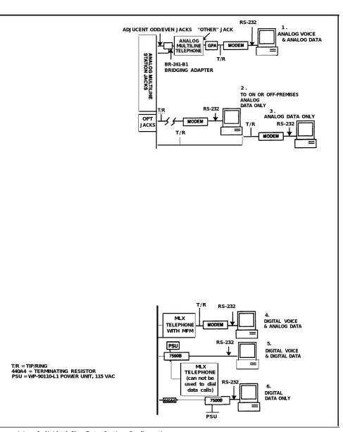
Diagrams of voice and data equipment commonly connected to the system are shown in the following pages. The numbers in the diagrams correspond to numbers in the accompanying text on the facing page. The text explains what the equipment is, where it’s connected to the control unit, and how it’s used to make data calls.
Individual Use Data Stations
Figure 1-1 shows configurations for an analog data station and a digital data station, both intended for individual use.
1.
2.
3.
4.
5.
6.
Analog Voice and Analog Data includes a data station with an endpoint,
such as a data terminal or PC connected via a modem, and an analog multiline telephone. A GPA supplies the tip/ring (T/R) interface for the modem. To provide simultaneous voice and data calls, two adjacent station jacks must be assigned on a 408, 408 GS/LS, or 008 module using a BR-241-B1 bridging adapter.
On- or Off-Premises Analog Data-Only is an endpoint connected via a
modem, Connection to the control unit is through an off-premises telephone (OPT) jack on a 008 OPT module.
Analog Data-Only is an endpoint connected via a modem to a basic station
jack on a 008 OPT or 012 (basic telephone) module in the control unit.
Digital Voice and Analog Data is an endpoint connected via a modem and
a Multi-Function Module (MFM) in an MLX telephone connected to the control unit. The modem converts the digital signal to an analog signal that is sent through the MFM in the MLX telephone connected to the control unit.
Digital Voice and Digital Data is an endpoint connected via an ISDN 7500B
Data Module attached to an MLX telephone. The ISDN 7500B Data Module supplies the RS-232 interface to the endpoint. The MLX telephone connects to a station jack on a 008 MLX module.
Digital Data-Only is an endpoint connected via an ISDN 7500B Data
Module. Since an MLX telephone is not attached, a 440A4 terminating resistor must be installed. The data station is connected to a station jack on a 008 MLX module.
RS-232
ADJUCENT ODD/EVEN JACKS "OTHER" JACK 1 .
ANALOG VOICE ANALOG
MULTILINE TELEPHONE
& ANALOG DATA
T/R BR-241-B1
BRIDGING ADAPTER
2 .
TO ON OR OFF-PREMISES ANALOG
DATA ONLY
T/R RS-232 3 .
OPT JACKS
ANALOG DATA ONLY T / R RS-232
T / R
T / R RS-232
MLX TELEPHONE
WITH MFM
RS-232
T/R = TIP/RING
440A4 = TERMINATING RESISTOR PSU = WP-90110-L1 POWER UNIT, 115 VAC
MLX TELEPHONE
(can not be used to dial
data calls)
RS-232
PSU
4.
DIGITAL VOICE & ANALOG DATA
5.
DIGITAL VOICE & DIGITAL DATA
6. DIGITAL DATA ONLY
Figure 1-1 Individual Use Data Station Configurations
Modem Pools and Data Hunt Groups
See "Data Hunt Group Planning" in Figure 1-2 shows analog modems and digital data modules assigned to modem Chapter 3 of this guide. pools and DHGs so that analog and digital stations can communicate with each
other.
1.
2.
3.
4.
Digital to Analog converts digital signals to analog signals so a digital
station can communicate with an inside or outside analog station. Each modem is assigned to a basic station jack on a 012 or 008 OPT (basic telephone) module, and each data module is assigned to a 008 MLX module.
Analog to Digital converts analog signals to digital signals so an analog
data station can communicate with an inside or outside digital data station. Each modem is assigned to a basic station jack on a 012 or 008 OPT (basic telephone) module, and each data module is assigned to a 008 MLX module.
Digital to Analog (Outgoing) converts digital signals to analog signals so a
digital data station can communicate with an outside analog station over outside dedicated lines. These lines are used solely for data
communications. The data module is connected to the control unit using station jacks on a 008 MLX module.
Analog to Digital (Incoming) converts digital signals to analog signals so a
digital data station can communicate with an outside analog station over outside dedicated lines. These lines are used solely for data
communications. The data module is connected to the control unit using station jacks on a 008 MLX module.
Note: Since an MLX telephone is not connected, a 440A4 terminating resistor
must be installed.
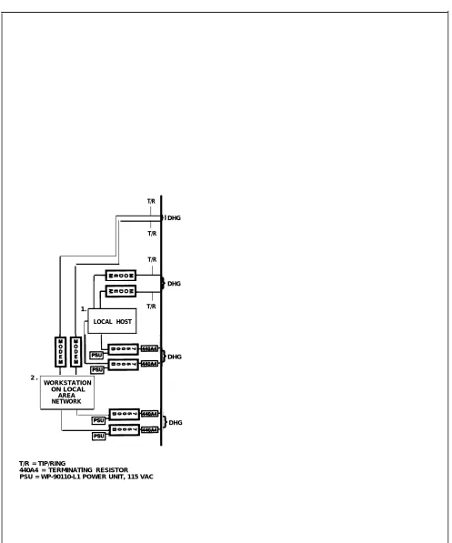
Local Host Computer and LAN Workstations
Figure 1-3 shows how data stations can be assigned to DHGs to provide access to a local host computer and a workstation on a local area network (LAN).
1.
2.
Local Host Computer connects a local host computer via a modem or data
module to the control unit.
The modems and data modules connect to RS-232 ports on the host computer. Each modem is assigned to a station jack on a 012 or 008 OPT module and each data module connects to a 008 MLX module station jack.
LAN Workstation connects a data terminal or computer (workstation) on the
IAN via modems or data modules to the system. A LAN is a group of terminals or PCs connected to each other or to a local host.
Figure 1-3 shows how a data station communicates with a local host computer or another workstation by dialing one extension number. For example, extension 711 could be assigned to the data station DHG, and extension 773 could be assigned to the modem DHG for communicating with the local host computer. Extension 774 could be assigned to the data station DHG and extension 775 could be assigned to the modem DHG for communicating with other
workstations on the LAN.
T/R
T/R
T/R
1. T/R
LOCAL HOST
2 .
WORKSTATION ON LOCAL
AREA NETWORK
T/R = TIP/RING
440A4 = TERMINATlNG RESISTOR PSU = WP-90110-L1 POWER UNIT, 115 VAC
DHG
DHG
DHG
DHG
Figure 1-3 Data Stations Connected to Local Host Computer and LAN Workstation
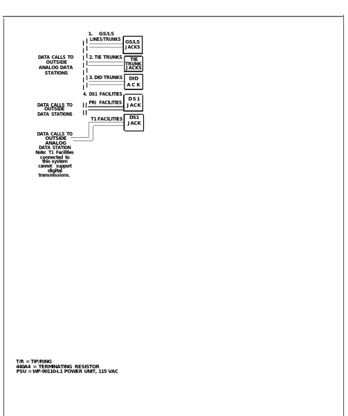
Outside Lines/Trunks
Figure 1-4 shows the types of outside lines/trunks that can be used to make and receive data calls to outside data stations.
1.
See System Reference for detailed 2.
information and programming requirements for tie trunks.
See System Reference for detailed 3.
information and programming requirements for DID trunks.
4.
GS (ground-start) Iines/trunks are used to place and receive data calls
from an outside analog data station and also provide improved signaling and a dependable disconnect (for secure toll restriction).
LS (loop-start) Iines/trunks are the standard for home and small
businesses. They are less expensive in some areas but
■ they do not protect against “glare." Glare occurs when an outside call is made at the same time as another call is arriving.
■ they cannot provide dependable disconnect for toll restriction
The following outside GS/LS lines/trunks can be used for data:
basic lines/trunks
WATS (wide area telecommunications service)
800 service (in-WATS)
foreign exchange (FX)
GS/LS Iines/trunks connect to GS/LS jacks on the system.
Tie Trunks provide private communications between two systems. Tie trunks
“tie” the two systems together, providing access to all telephones or data stations on each system.
Tie trunks are usually used for data communication with analog stations connected to a system at a different location, such as different floors of a building, different buildings, and different cities or states.
Tie trunks connect to the system on a 400EM module.
DID (Direct Inward Dial) Trunks allow incoming calls to reach specific
individuals or facilities in the system without the help of a system operator. DID trunks are available only in the Hybrid/PBX mode.
DID trunks are used to receive calls from outside analog data stations. Outgoing calls cannot be placed on DID trunks.
DID trunks connect to the system on an 800 DID module.
DS1 facility carries digital signals in the Digital Signal 1 (DS1) format.
The DS1 format passes digital data at 1.5444 Mbps by multiplexing twenty-four 64-kbps Digital Signal 0 (DS0) signals and an 8-kbps framing signal. Even though there is only one physical jack, the 100D module supports up to twenty-four logical endpoints or ports (one for each channel) for voice and data calls.
Each DS0 channel in the DS1 signal corresponds to a line/trunk or logical ID.
1. GS/LS LINES/TRUNKS
GS/LS JACKS
DATA CALLS TO OUTSIDE ANALOG DATA
STATIONS
2. TIE TRUNKS TIE TRUNK
JACKS
3. DID TRUNKS DID A C K
4. DS1 FACILITIES D S 1 DATA CALLS TO PRI FAClLITIES JACK
OUTSIDE DATA STATIONS
T1 FAClLITIES DS1 JACK
DATA CALLS TO OUTSIDE ANALOG DATA STATION Note: T1 Facilities
connected to this system cannot support
digital transmissions.
T/R = TIP/RING
440A4 = TERMINATING RESISTOR PSU = WP-90110-L1 POWER UNIT, 115 VAC
Figure 1-4 Outside Lines/Trunks
The DS1 provides a digital signal so data calls from a digital station can be placed to outside digital stations and transmitted at higher speeds (up to 56 kbps).
A DS1 facility provides either T1 or PRI access. See System Reference for detailed
information and programming requirements for DS1 facilities.
T1 is the factory setting. Each of the 24 channels can emulate any combination of E&M tie, LS, or GS lines/trunks. A single 100D module can replace 24 outside lines/trunks. T1 facilities are used to place and receive data calls from outside analog data stations. Outside digital data
communications are not supported.
ISDN-PRI is the standard format for ISDN service. Any combination of the following AT&T Switched Network (ASN) Services provided through an ISDN-PRI line/trunk can be used:
■
■
■
■
Accunet® switched digital service for 56-kbps and 64-kbps restricted, and 64-kbps clear circuit-switched data calls
Megacom® WATS service for domestic long-distance outward voice calls
Megacom® 800 for domestic toll-free voice calls
Software Defined Network (SDN) for voice and circuit-switched data calls (up to 56 kbps)
The benefits of ISDN-PRI include
Speed. Data calls to outside destinations can be made on the same B channels used for voice calls if the service allows. Modems and dedicated, conditioned lines/trunks are not needed.
AT&T’s INFO-2 automatic number identification (ANI) service. Customers who subscribe to this service can identify the caller on an incoming call on an ISDN-PRI line/trunk by either telephone number or billing number.
Note: The availability of the caller identification information may be
limited by local-serving (caller’s) jurisdiction, availability, or central office equipment.
Dynamic B-channel assignment. An individual B channel can be removed from service without blocking calls to or from any other B channels.
Improved toll restriction. Bypassing of toll restriction is limited on ISDN-PRI lines/trunks.
Reliable indication of far-end disconnect. Blocking of incoming calls is prevented because a line/trunk is not immediately released; instead there is a delayed indication of disconnect.
Improved SMDR reports. Call timing for SMDR reports is improved since calls recorded are closer to the actual billed duration.
Shared use of B channels for Megacom WATS and Megacom 800 on a call-by-call basis for more efficient use of facilities.
2
ISDN 7500B Data Modules and modems connect data terminal equipment (DTE) such as a PC, printer, optical scanner, local host computer, or LAN workstation to the communications system.
This chapter explains how data modules and modems work, how they connect to the system, how to configure them, and the features they offer.
ISDN 7500B Data Module
The Integrated Services Digital Network (ISDN) 7500B Data Module connects digital data terminal equipment to the system via a 008 MLX module on the system. Unlike a modem, which converts digital data signals to analog signals, a data module transmits digital data to other digital stations.
The data module provides an RS-232 interface for asynchronous transmission from DTE at speeds of up to 19.2 kbps. It can also provide a V.35 interface for synchronous transmission at speeds of up to 64 kbps if you order a separate board.
Figure 2-1 shows the following on the lSDN 7500B Data Module’s front panel:
POWER/TEST LED. Lights when power is supplied and flashes when tests
are made.
DATA LED. Flashes when a data call comes in and lights when a call is in
progress; flashes when tests are made.
Display. Shows status information and option settings.
NEXT, BACK, and ENTER buttons. Used to operate the data module and to
adjust the screen’s contrast.
Figure 2-1 also shows the following on the underside of the ISDN 7500B Data Module’s top cover:
■ DCE/DTE Flip Board. Used to select whether the data module operates with
data terminal equipment connected directly or as part of a modem pool.
DCE/DTE Flip Board
Figure 2-1 ISDN 7500B Data Module Front Panel
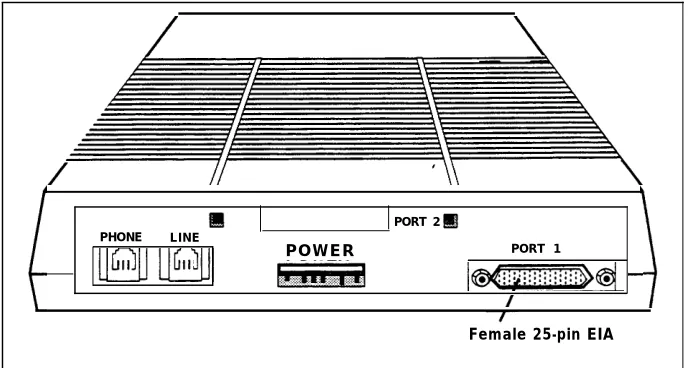
Figure 2-2 shows the following on the data module’s back panel:
PHONE jack. Connects an MLX telephone to the data module.
LINE jack. Connects the data module to the digital station jack on the 008
MLX module.
POWER connector. Connects the data module to the DC power supply,
which connects to an AC outlet.
PORT 1. Connects the data module to a data terminal (such as a PC) or,
when the data module is used in a modem pool, to a modem.
PORT 2. When an enhancement board is installed for synchronous
operation, connects a second data terminal, an automatic calling device (with an RS-366 interface), or a data terminal with a V.35 interface (depending on the type of enhancement board you have).
PORT 2 PHONE L I N E
POWER PORT 1
Female 25-pin EIA
Figure 2-2 ISDN 7500B Data Module Back Panel
Hardware
When you use the ISDN 7500B Data Module with an MLX telephone, one end of a D8W cord connects to the PHONE jack on the data module and the other end of the cord connects to the LINE jack on the MLX telephone.
When you use the ISDN 7500B Data Module without an MLX telephone, you must install a 100-ohm 440A4 terminating resistor adapter (PEC 2709-A59) on the line near the data module.
Note: You cannot locate the data module more than 80 feet from the telephone.
You can configure the data module as a stand-alone (order a WP-90110-L1 power unit [PEC 21625]) or in a multiple-mount arrangement (order a Z77A data mounting [PEC 21626]). The multiple-mount arrangement provides a common power supply for up to eight data modules. Both the power unit and the data mounting need a 115-VAC power outlet. You must order the power unit and data mounting separately.
For synchronous operation at speeds of up to 64 kbps, order one of the following circuit boards:
■
Features
Multipurpose Enhancement Board. Provides an RS-366 Automatic Calling
Unit (ACU) interface on PORT 2 and converts the RS-232 interface on PORT 1 on the main circuit board from asynchronous to synchronous. You must order a V.35 adapter cable separately to operate at data rates of 56 and 64 kbps. Without the adapter cable, data rates are limited to 1200, 2400, 4800, 9600, and 19,200 bps.
High-Speed Synchronous Interface Enhancement Board. Provides a V.35
interface at synchronous data rates of 48, 56, or 64 kbps on PORT 2. A V.35 adapter cable that converts the 25-pin male connector on PORT 2 to the industry-standard 34-pin V.35 interface is included. PORT 1 is not used.
See the Integrated Services Digital The data module offers both asynchronous and synchronous features:
Network (ISDN) 7500 Data Module
User’s Manual for detailed information Asynchronous Features
on the features available and how they are used for data calls. ■
■
■
■
■
■
■
RS-232 interface
asynchronous full-duplex operation
data rates of 300, 1200, 2400, 4800, 9600, or 19,200 bps
data options set by data terminal equipment
data options set without dropping a data call
autobaud (also called data metering or speed matching)—adjusts the transmission speed to match the speed of the data terminal being called
auto-adjust—adjusts to the speed and parity of the data terminal equipment used
■ call setup (dialing) from the keyboard of an ASCII data terminal using the local command (CMD) mode or AT mode
■ automatic or manual answering of incoming data calls
Synchronous Features with Multipurpose Enhancement Board
RS-232 interface
half- or full-duplex operation using the RS-232 interface at data rates of 1200, 2400, 4800, 9600, and 19,200 using data transport Mode 2
half- or full-duplex operation at 56 kbps with the V.35 interface adapter cable
full-duplex operation at 64 kbps with the V.35 interface adapter cable
automatic answering of incoming data calls
ability to place outgoing data calls manually and select user-programmable telephone numbers from the data module display on the front panel
RS-366 interface to an automatic calling unit (ACU)
Synchronous Features with High-Speed Synchronous Enhancement Board
V.35 interface (The adapter cable is provided when you order the board using PEC 21624.)
full-duplex operation at 48, 56, and 64 kbps
half-duplex operation at 56 kbps only
automatic answering of incoming data calls
ability to place data calls manually and select user-programmable telephone numbers from the data module display on the front panel
Modems
A modem is used at an analog data station to place or answer data calls. Modems convert outgoing digital signals from the data terminal into analog signals for transmission, and convert incoming analog signals to digital signals for the data terminal.
Hardware
Since you can connect different types of modems to the system, specific modem hardware is not discussed in this’ book. Modems also provide a variety of features in addition to the basic features listed below. Modems used in modem pools, however, must have the following features:
full-duplex operation
support of 10-bit code (start, 8 data bits, stop)
RS-232 asynchronous interface
data rates of 300, 1200, 2400, 4800, and 9600 bps
dual-tone multi-frequency (DTMF) dialing through the RS-232 interface
ability to turn on or maintain the Clear-to-Send indicator when it is ready to receive ASCII dialing sequences from the data module in response to a Data-Terminal-Ready signal from the data module
ability to keep the Data-Set-Ready lead on (and not turn it off) during transition from the interactive dialing mode to the data mode
ability to terminate a data call or dialing sequence when the data module turns off its Data-Terminal-Ready lead
ability to turn off the Data-Set-Ready or Receive-Line-Signal-Detect lead for a minimum of 50 ms when hanging up at the termination of a data call
ability to turn on the Ring indicator lead for at least 100 ms in the presence of an incoming analog call
support of Electronic Industries Association (EIA) signals Cl and CI2 if the modem is multispeed
AT&T model 2224G (PEC 2224-CEO for stand-alone, PEC 2224-GED for rack-mounting arrangement) is recommended for modem pools.
See System Reference for information To use a modem with an MLX telephone, install a Multi-Function Module (MFM) on the MFM and GPA. in the telephone to provide a tip/ring (T/R) interface for the modem. The modem
connects directly to the MFM. You use the data terminal keyboard to dial data calls and use the telephone dialpad to dial voice calls. Each device operates independently, and features are assigned to each device independently.
To use a modem with an analog multiline telephone, install a General Purpose Adapter (GPA) to provide a T/R interface. You use the telephone dialpad to dial data and voice calls. Features assigned to the telephone are also assigned to the analog data station.
Features
Analog data stations (those not in a modem pool) in the system offer the following features, depending on your modem:
dialing of asynchronous data calls from the keyboard when connected to a basic telephone station jack on a 012 or 008 OPT module or when connected to an MLX telephone using an MFM
autobaud (also called data metering or speed matching) for adjusting the speed of transmission to match the speed of the data terminal being called
automatic or manual answering of incoming data calls
self-test and maintenance procedures
ability to set data options for the call on the keyboard and change-the options without dropping the call
Modem Pools
A modem pool (also called a conversion resource) consists of one or more pairs of data modules and modems. A modem pool converts data signals from digital to analog or from analog to digital for communications between digital and analog data stations.
Modem pools can be
■
■
Analog to Digital. Converts analog signals to digital signals so that analog
data stations can communicate with inside digital stations or outside digital ISDN-PRI facilities.
Digital to Analog. Converts digital signals to analog signals so that digital
data stations can communicate with inside analog data stations or place data calls using the regular telephone network.
Modem pools can operate in one direction only—analog-to-digital or digital-to-analog (incoming or outgoing). Dedicated outside digital-to-analog lines can be
connected directly into analog modems in an analog-to-digital modem pool (and through a data module to 008 MLX ports on the system).
Hardware
In a modem pool, the modem connects to the control unit via a basic station jack on a 012 or 008 OPT module. An ISDN 7500B Data Module (PEC 2164-BDM) connects to the control unit via a digital station jack on a 008 MLX module.
In an analog-to-digital modem pool, data calls are placed to outside data stations through the control unit using system lines (outside ISDN-PRI facilities connected to the DS1 line/trunk jack on a 100D module in the control unit).
In a digital-to-analog modem pool, data calls are placed to outside data stations through the control unit using system lines (outside lines/trunks connected to a line/trunk jack on a 400, 400 GS/LS/TTR, 800, 800 GS/LS, 408, 408 GS/LS, 800 DID, or 400EM module in the control unit).
Since the data module in a modem pool operates without an MLX telephone, you must install a 100-ohm 440A4 terminating resistor adapter (PEC 2709-A59) on the line near the data module.
You can configure the ISDN 7500B Data Module as a stand-alone by ordering a WP-90110-L1 power unit (PEC 21625) or in a multiple-mount arrangement by ordering a Z77A data mounting (PEC 21626). The Z77A provides a common power supply for up to eight data modules. Both the power unit and the data mounting require a 115-VAC power outlet. Neither is provided with the data module and both must be ordered separately.
Option Settings
See the user manuals provided with the The options set for a modem and data module in a modem pool differ
modem and the lSDN 7500B Data depending on whether the modem pool is digital-to-analog or analog-to-digital. Module for setting hardware and
software options, and for explanations
of the options. If the modem or Data Module is rack-mounted, you may have to supply or remove power to a single modem or data module.
Digital-to-Analog Settings Data Module Setting
To prepare the data module for a digital-to-analog modem pool:
1. Set the DCE/DTE flip board to the DTE position.
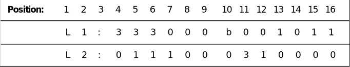
2. Use the front panel controls on the data module to get the following option display.
Table 2-1 Data Module Settings for Digital-to-Analog Modem Pool
Position: 1 2 3 4 5 6 7 8 9 10 11 12 13 14 15 16
L 1 : 3 3 3 0 0 0 b 0 0 1 0 1 1
L 2 : 0 1 1 1 0 0 0 3 1 0 0 0 0
b = blank L = Line #
Modem Setting
The AT&T model 2224G modem is designed for modem pools. One way to prepare this modem for operation in a digital-to-analog modem pool is shown below and may be different depending on your type of modem.
1.
2.
3.
4.
5.
6.
Connect a data terminal such as a PC to the modem and plug both the modem and data terminal into an AC outlet.
Use the instructions provided with the modem to set all bit switches to default positions.
Save all bit-switch settings by unplugging the modem from the wall outlet and plugging it back in.
Set the data terminal speed to match the modem’s default speed.
The modem is now operating in the AT&T command protocol. Use these steps to set the default options:
■ Type o d .
■ Press Enter.
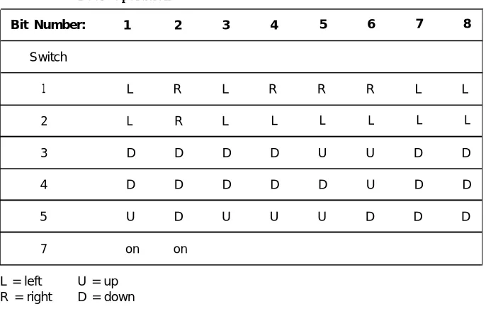
Set all bit switches according to Table 2-2.
Table 2-2 Modem Option Settings for Digital-to-Analog Modem Pool Operation
Bit Number: 1 2 3 4 5 6 7 8
Switch
1 L R L R R R L L
2 L R L L L L L L
3 D D D D U U D D
4 D D D D D U D D
5 U D U U U D D D
7 on on
L = left U = up R = right D = down
7.
8.
Unplug the modem from the wall outlet; then plug it back in. Set switch 1, bit 2 to the left to store the switch settings in the modem’s memory. The modem is now operating in the AT&T command protocol.
Enter command mode, set the options, and save the options in protected memory to prevent loss of settings in case of a power failure:
■
■
■
■
■
■
Type AT and press Enter to enter the local mode.
Type AT&D2 and press Enter. Option set: drop call when DTR low.
Type AT&C1 and press Enter. Option set: data carrier detect follow call.
Type ATS0=1 and press Enter. Option set: Auto Answer.
Type ATQ0 and press Enter. Option set: enable result codes (factory setting).
Type AT&W and press Enter to save the options in protected memory and prevent loss of settings in case of a power failure.
Analog-to-Digital Settings ISDN 7500B Data Module Option Setting
Use the following procedure to prepare the ISDN 7500B Data Module for operation in an analog-to-digital modem pool:
1. Set the DCE/DTE flip board to the DTE position.
2. Use the front panel controls on the data module to see the following.
Table 2-3 Data Module Settings for Analog-to-Digital Modem Pool
Position: 1 2 3 4 5 6 7 8 9 10 11 12 13 14 15 16
L 1 : 3 3 3 0 1 0 b 0 0 1 0 1 0
L 2 : 0 1 1 1 0 0 0 3 1 0 0 0 0
b = blank L = Line #
Modem Setting
The AT&T model 2224G modem is designed for modem pools. One way to prepare this modem for operation in a digital-to-analog modem pool is shown below and may be different depending on your type of modem:
1.
2.
3.
4.
5.
6.
Connect a data terminal such as a PC to the modem and plug both the modem and data terminal into an AC outlet.
Use the instructions provided with the modem to set all bit switches to the default positions.
Save all bit-switch settings by unplugging the modem from the wall outlet and plugging it back in.
Set the data terminal speed to match the modem’s default speed.
The modem is now operating in the AT&T command protocol. Use these steps to set the default software options:
■ Type o d .
■ Press Enter.
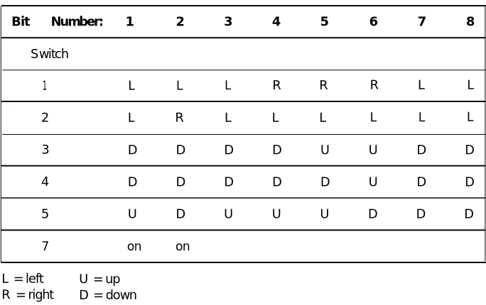
Set all bit switches according to Table 2-4.
Table 2-4 Modem Settings for Analog-to-Digital Modem Pool
Bit Number: 1 2 3 4 5 6 7 8
Switch
1 L L L R R R L L
2 L R L L L L L L
3 D D D D U U D D
4 D D D D D U D D
5 U D U U U D D D
7 on on
L = left U = up R = right D = down
7. Unplug the modem from the wall outlet; then plug it back in. Set switch 1, bit 2, to the left to store the switch settings in the modem’s memory. The modem is now operating in the AT&T command protocol.
8. Set the options, and save the options into protected memory to prevent loss of settings in case of a power failure:
■ Type AT and press Enter to enter the local mode.
■ Type AT&D2 and press Enter. Option set: drop call when DTR low.
■ Type AT&C1 and press Enter. Option set: data carrier detect follow call.
■ Type ATS0=1 and press Enter. Option set: Auto Answer.
■ Type ATQ1 and press Enter. Option set: disable result codes.
■ Type AT&W and press Enter to write options to protected memory
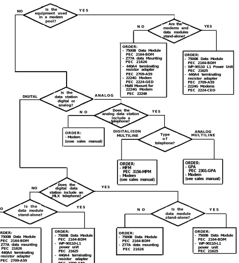
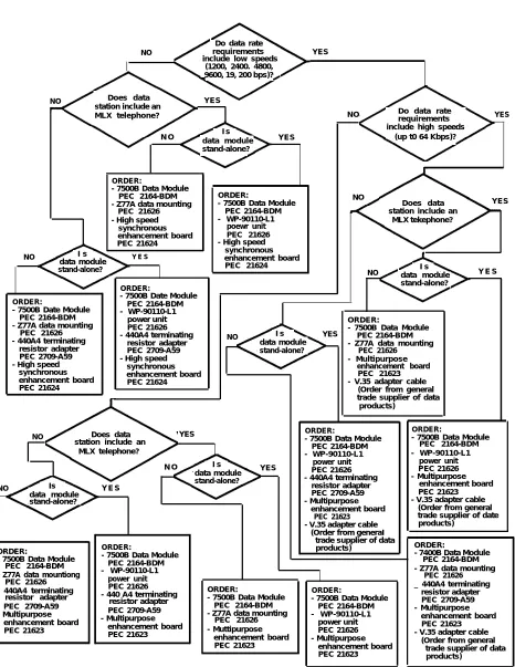
Hardware Decision Flowcharts
The following flowcharts show hardware required for specific data communications uses. Figure 2-3 is for asynchronous transmission and Figure 2-4 is for synchronous transmission.
NO Is the Y E S equipment used
in a modem pool?
Are the N O modems and
data modules stand-alone?
YES
Is the
DIGITAL data station A N A L O G digital or
analog?
N O Does the Y E S
analog data station include a telephone?
O R D E R : D I G I T A L / I S D N Type ANALOG - Modem M U L T I L I N E M U L T I L I N E (ssee sales manual) telephone?o f
ORDER: ORDER:
- MFM - GPA
PEC 3156-MPM PEC 2301-GPA
- Modem - Modem
(see sales manual) (see sales manual)
Does the
NO digital data Y E S station include an
MLX telephone?
NO I s t h e Y E S Is the
ORDER:
- 7500B Data Module PEC 2164-BDM - Z77A data Mounting
PEC 21626 - 440A4 terminating
resistor adapter PEC 2709-A59 - 2224G Modem
PEC 2224-GED - Malti Moount for 2224G Modem
PEC 22248
ORDER:
- 7500B Data Module PEC 2164-BDM
- WP-90110 L1 Power Unit PEC 21625
- 440A4 terminating resistor adapter PEC 2709-A59 - 2224G Modems PEC 2224-CEO
data module stand-alone?
N O Y E S
data module stand-alone?
ORDER:
. 7500B Data Module PEC 2164-BDM - Z77A data mounting
PEC 21626 - 440A4 terminating
resistor adapter PEC 2709-A59
ORDER:
- 7500B Data Module PEC 2164-BDM - WP-90110-L1
power unit PEC 21625 - 440A4 terminating
resistor adapter PEC 2709-A59
ORDER:
- 7500B Data Module PEC 2164-BDM - Z77A data mounting
ORDER:
- 7500B Data Module PEC 2164-BDM - WP-90110-L1
power unit PEC 21625 PEC 21626
Figure 2-3 Asynchronous Hardware Decision Flowchart
Do data rate
NO requirements YES
include low speeds (1200, 2400. 4800, 9600, 19, 200 bps)?
NO Does data YES
station include an
MLX telephone? NO Do data rate
requirements YES
I s include high speeds
N O data module stand-alone?
YES (up t0 64 Kbps)?
NO
Does data YES
PEC 21626 station include an
MLX tekephone? PEC 21624 NO data module stand-alone? ORDER:
- 7500B Data Module PEC 2164-BDM - Z77A data mounting
I s Y E S
I s data module stand-alone?
Y E S
ORDER:
- 7500B Date Module PEC 2164-BDM - Z77A data mounting
PEC 21626 - 440A4 terminating
resistor adapter PEC 2709-A59 - High speed
synchronous enhancement board PEC 21624
- High speed synchronous enhancement board
ORDER:
- 7500B Date Module PEC 2164-BDM - WP-90110-L1
power unit PEC 21626 - 440A4 terminating
resistor adapter PEC 2709-A59 - High speed
synchronous enhancement board PEC 21624
ORDER:
- 7500B Data Module PEC 2164-BDM - WP-90110-L1
poewr unit PEC 21626 - High speed
synchronous enhancement board PEC 21624
I s YES
data module stand-alone?
enhancement board PEC 21623 - V.35 adapter cable
(Order from general trade supplier of data
Does data YES station include an
MLX telephone?
N O I s YES
data module stand-alone? Is Y E S
data module stand-alone?
ORDER:
- 7500B Data Module PEC 2164-BDM - Z77A data mountiong
PEC 21626 - 440A4 terminating
resistor adapter PEC 2709-A59 - Multipurpose enhancement board PEC 21623 ORDER:
- 7500B Data Module PEC 2164-BDM - WP-90110-L1
power unit PEC 21626