Development of a Virtualized Application Networking Infrastructure Node
Keith Redmond∗, Hadi Bannazadeh∗, Paul Chow∗, and Alberto Leon-Garcia∗
∗The Edward S. Rogers Sr. Department of Electrical and Computer Engineering, University of Toronto, Canada [email protected], [email protected], [email protected], [email protected]
Abstract—This paper describes the design of a Virtualized Application and Networking Infrastructure (VANI) node that can be used to facilitate network architecture experimentation. Currently the VANI nodes provide four classes of physical resources: processing, reconfigurable hardware, storage and interconnection fabric, but the set of sharable resources can be expanded. Virtualization software allows slices of these resources to be apportioned to VANI nodes that can in turn be interconnected to form virtual networks that can operate according to experimental network and application protocols. We discuss the design decisions that have been made in the development of this system and we provide a detailed description of the prototype, including how users interact with the resources and the interfaces provided by the virtualization layers.
Keywords-testbed; architecture; virtualization; next-generation Internet; application-oriented networks
I. INTRODUCTION
The success of the Internet has influenced almost all aspects of our society. This success has resulted in rapid growth for the Internet, both in terms of the amount of data traffic, and the diversity of application run upon it. However, many new challenges have been exposed by this growth in areas such as scalability[1], flexibility[2], reliability[3] and security[4]. Resolving these challenges will most likely require changes to the current Internet architecture[5][6].
What this future architecture will look like is currently an open research question. There has been a significant amount of work done in this field (e.g. [7], [8], [9], [10], [11]). However, it is difficult to compare and contrast such ideas because it is difficult to run large-scale experimentation for new networking architectures. Therefore, what is needed is an infrastructure that simplifies the processes of developing such large-scale experiments.
One testbed currently in use for testing networking ideas is called PlanetLab [12]. PlanetLab is an overlay that runs over the Internet, and has been created for the purpose of distributed application testing. This overlay contains a number of processors that researchers may reserve to run custom software on. However, while PlanetLab does provide a testbed for testing distributed software, it supports proces-sors as the only resource type. Further, PlanetLab does not provide the option to run on dedicated fabric, which means experiments may be affected by live traffic conditions, and researchers may not experiment with new layer 3 protocols.
A new initiative called the Global Environment for Net-working Innovations (GENI) [13] is attempting to rectify some of the shortcomings of PlanetLab. This initiative plans develop an infrastructure containing nodes with heteroge-neous resources available for researchers to access and use for networking experimentation. Further, it is expected that GENI will use the National LambdaRail infrastructure [14], to provide a dedicated routing fabric for further control over the network.
In [15], an application-oriented approach to exploring fu-ture networking alternatives is proposed. This work presents a reference model, called the Application-Oriented Networks (AON) reference model, in which applications are created through the composition of programmable resources and services provided, possibly, by other researchers.
This paper attempts to build on the work done in [15] by presenting a Virtualized Application and Networking Infrastructure (VANI) node. This is a working prototype of a node consisting of multiple programmable and non-programmable resources that have been virtualized as ser-vices that can be used and networked together. Further, these services can be used to develop powerful packet processing techniques, testing new network architectures. However this infrasructure can be used as an architecture for future networks where applications are deployed direcly on the network, and the network provides a series of services, as opposed to simply being a data transmission system. Finally, this paper provides an example of the use of VLANs [16] to provide performance isolation, and highlights some of the complexities that can arise when using this mechanism on a physical resource supporting multiple virtual resources.
II. TESTBEDDESIGNPRINCIPLES
In our design we followed five basic requirements: First, the infrastructure should allow experimentation for future network architectures that might not fit into the traditional layered definitions. For example, it might be possible for future transport planes in a network to perform tasks such as rich content delivery in addition to the raw data delivery [15]. To do so, we need to have nodes that could do content delivery related tasks such as content processing and storage. The second requirement is to allow researchers to exper-iment with new layer three protocols (as in the traditional definition of L3) instead of the current Internet Protocol. Another requirement in the testbed is to be able to setup
experiments or create new applications rapidly using already developed and ready to use components that could be accessed through open interfaces. This requirement could be satisfied through the use of the SOA technologies and standards such as Web Services that could allow flexible and dynamic composition of reusable service components.
The forth requirement is to provide an isolated and secure environment for researchers to perform their experiments and develop their networked applications. The fifth require-ment is to include monitoring and debugging mechanisms. In our design, we envisioned powerful complex event pro-cessing components that could be customized to gather and analyze test and debugging data for each experiment separately as well as for the testbed itself.
Based on these main requirements, we designed a two plane architecture for our platform: the control and man-agement plane (TB-CMP) and the application plane. Due to the near universal acceptance of the Web Services (WS) and SOA technologies, we utilized WS interfaces for accessing the in-platform resources, and through the use of Business Process Execution Language (BPEL) in our control plane we can dynamically assign these resources to the researchers and application providers. On the other hand in the ap-plication plane, the researchers and apap-plication providers could have their own custom designed layered architecture in isolation from other applications and experiments.
In this paper, we discuss the steps and design choices in the development of the virtualized physical resources in this Virtual Application Networking Infrastructure, and we describe how researchers can test their ideas in isolation within this environment.
III. NETWORKINGVANINODES
The VANI nodes provide Web Services interfaces to the TB-CMP. Each resource type contained on a VANI node is controlled by a Web Service, meaning that each VANI node has multiple Web Services. When a researcher wants to communicate with a resource using these Web Services interfaces, they would first contact the TB-CMP.
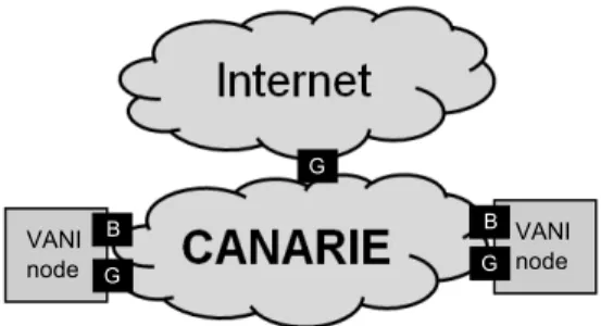
In the application plane, researchers are permitted to contact their resources directly to run their experiments. Direct access to resources always takes place through a gateway, however the gateway that is used depends on the type of network a researcher is using for their experiments. It is anticipated that there will be a two-phase development process for interconnecting VANI nodes. The first phase will involve carrying the traffic directly over the Internet. Although not ideal, as it does not provide researchers with tight control over traffic conditions, it is faster to develop. The second phase uses traffic carried by Ethernet across a wide area using networks such as CANARIE [17], which provides researchers with a dedicated network and allows them to develop custom protocols above layer 2. Figure 1
Figure 1. Connectivity of two VANI nodes with the CANARIE network. G stands for gateway, and it handles IP packets. B stands for bridge, and it handles raw Ethernet frames.
shows the connectivity of two nodes using the CANARIE network.
A. Internet Connectivity
When a resource is allocated to a researcher, it is given an internal IP address. When providing access to the Internet, this internal IP address must be converted to an externally visible IP address using a gateway that does NAT. This gateway will be provided with multiple externally visible IP addresses that researchers may book and associate with the internal IP address of their required resource. Currently a solution to do this is being developed using the reconfig-urable hardware resource (section V-C) to reach speeds of 10 Gbps.
B. Ethernet Connectivity
Once the VANI nodes have been connected to a network such as CANARIE, packets from the Internet will need to traverse two gateways to reach the internal resources: one to enter the CANARIE network, and one to enter the VANI node. The reasons for connecting with CANARIE are twofold. First, CANARIE will provide a dedicated fabric on which experimental traffic may be carried. This will allow researchers tight control over the conditions of their experiments, allowing them to do things such as injecting failures into the network. The second reason for connecting with CANARIE is that it provides raw Ethernet connectivity. The VANI nodes must run on Ethernet technology, however it does not assume any physical layer connectivity, nor does it assume any protocols above layer 2. This allows the network to support experiments with new protocols above layer 2 (for example, IP need not be used, although it may be).
C. Performance Isolation
Since the purpose of the VANI nodes is to support networking experimentation, it is important that each re-searcher’s virtual network be isolated from the others, to prevent inadvertent or intentional interference with another researcher’s experiments. To do this, each VANI node uses
VLANs [16], which use tags to prevent traffic from reach-ing a resource that has not been granted access to the researcher’s tag. Normally a researcher will have a private tag (or tags) that only they have access to. However, it is possible to add another researcher’s VLAN to a resource, provided both researchers consent to this assignment. This allows researchers to have experiments intercommunicate, but only when this is desired.
One restriction of VLANs is that the tags are only 12-bits long, meaning there are only 4096 total VLAN tags available. For this reason, VLAN tags are only local to a VANI node. However, there must be a mechanism to allow the gateway to know which VLAN to send an incoming packet on. When connected to the Internet, a routing table is maintained on the gateway and the destination subnet is used to determine the VLAN.
On the other hand, when connected to CANARIE, some experiments may not use IP. Thus, to identify packets within the CANARIE network, Q-in-Q tagging as defined in the IEEE 802.1ad standard [18] is used. In Q-in-Q tagging, two 12-bit tags are added to the packet: an outer tag and an inner tag. Under most networking conditions the outer tag is used by the provider, while the inner tag is used by the user to maintain VLAN tags across the network. However, within this network design the VLAN tags need not be maintained, as they are only local tags. Thus the outer and inner tag are combined to create a single 24-bit tag. Each researcher is given a globally unique, 24-bit Q-in-Q tag and each packet in the network is tagged with their Q-in-Q tag.
IV. ARCHITECTURE
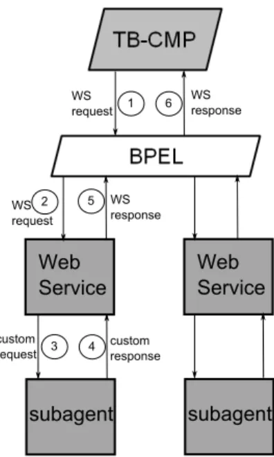
The current prototype for the VANI nodes has four resource types, although more will be added in the future. The first three resources – processing, reconfigurable hard-ware (RH), and storage – are available for researchers to access through the TB-CMP. Of these three, the processing RH are programmable resources, while storage is non-programmable. The final resource, the fabric, is an internal resource that is automatically configured by the TB-CMP. The virtualization layer for each of the resource types consist of three main components: a BPEL, a Web Service, and a number of subagents. The messaging flow is presented graphically in Figure 2.
The first component within the virtualization layer is the BPEL. The BPEL is the component that orchestrates communications between different Web Services within a VANI node. This component is transparent to the TB-CMP: the BPEL appears as a series of Web Services interfaces, and the partitioning of messages to communicate with the underlying Web Services is taken care of automatically by the BPEL. One example of when a BPEL is required is for the resourceGet message (see section V-A). When a resource is reserved, the fabric must be configured, and the resource must be allocated to the researcher.
Figure 2. Messages between TB-CMP and Web Service (WS). 1) web
service message is received by the BPEL. 2) The BPEL forwards selected parts of the message to the web services. 3) if well-formed, WS request is reformatted and sent to subagent. 4) the subagent responds to the message. 5) WS responds to the BPEL. 6) The responses from the Web Services are formatted, and forwarded to the TB-CMP.
The second component is the Web Service. The job of the Web Service is to ensure that messages sent to the VANI nodes are well-formed. Additionally, the Web Service will perform control-related checks such as determining which virtual resources have been allocated, and releasing a virtual resource once the time has expired. If a message is well-formed and passes the control-related checks, the Web Service will forward the required information using a custom protocol to the final component: the subagent.
The subagent is software that resides directly on the physical resource being controlled. Since a physical resource may consist of multiple virtual resources, the subagent is responsible for one or more virtual resources. It receives messages using a custom protocol selected that resource type because different resources will have different requirements in terms of message complexity, and will have differing computational resources available for parsing messages.
The purpose of the subagent software is to run the necessary scripts to set up, control, and tear down virtual resources. For example, when a GET request is received for a processing resource, a skeleton for a virtual processor is created. Further, when a PROGRAM request (see section V-A) is received, the subagent will receive an image file which will be extracted into the appropriate location, and the virtual processor will be started.
V. WEBSERVICESINTERFACES
The main interfaces for the programmable resources are presented in Table I. There are more interfaces for control
Table I
IMPORTANTWEBSERVICE INTERFACES FOR PROGRAMMABLE RESOURCES
Name Description
resourceList List the resources the web service man-ages
resourceGet Reserve a resource for a researcher to use for a certain timeframe (or until the researcher releases the resource if that is what is requested)
programResource Place an image on a resource, and start it running
resourceStatus Get the status of a resource
resourceRelease Release the resource, allowing anyone to reserve it
Figure 3. Example of a request that would reserve a resource for a researcher for 1 hour.
and resource-specific commands, but the ones in Table I are the most important. The next section will provide a brief overview of how the TB-CMP would interact with the programmable resources using these interfaces, to provide researchers with the necessary functionality. After this, more detailed view of each resource will be presented.
A. Main Interfaces Overview
Initially, the TB-CMP will likely list the resources avail-able from a particular Web Service. This will provide it with a list of universally unique identifiers (UUIDs) which list the virtual resources available from this Web Service. Next, when a researcher would like to use a particular type of resource, the TB-CMP would get one of the resources by supplying one of the UUIDs provided by the list command. The get command reserves the resource for particular re-searcher’s exclusive access for a specified time, or until it is manually released. An example of a get request is shown in Figure 3.
Once a resource has been reserved, it is possible for that resource to be programmed. Programming a resource involves sending the Web Service an image file, which is then installed on the specified resource. Examples of image files include bitstreams for reconfigurable hardware, or a tar archive of a filesystem for a processor. Once programmed, the resource is automatically started.
Finally, once a researcher has finished with the resource, they may release it. Releasing a resource removes the researcher’s image from the resource, places the resource in a known state, and puts the resource back into the pool of available virtual resources.
B. Processing
The processing resource was developed using the Linux-Vserver [19] software, which allows multiple virtual pro-cessors to be instantiated on a single server. These virtual processors share a kernel, which allows the resource provider to have some control over what a vserver may do. However, it does restrict processors to the Linux operating system.
Each virtual processor within a VANI node is a vserver. When programming a vserver, researchers provide a tar archive of a Linux filesystem. This filesystem is then ex-tracted by the processing subagent into the directory that will act as the root directory for that vserver. Finally, the vserver is started by the subagent, after which researchers may access their resource directly.
One complication that was found when running multiple vservers on a single physical node is that all vservers use the host’s routing table for determining where to send packets. This allows the host to act as a kind of gateway, enabling packets from a vserver to access VLANs that were allocated to a different vserver on the physical processor. This behaviour is undesirable, as it breaks the performance isolation provided by the VLANs.
To prevent this from happening, a firewall is used. This firewall will drop any packets in which both the source and destination IP address are internal resources (within the 10.X.X.X range), if they are on different subnets. This methodology works because IP addresses are assigned to internal resources in such a way that different VLANs are always found on different subnets. Thus, by setting the netmask properly, it is possible for the firewall to determine when a vserver is attempting to access a VLAN it should not have access to, and drop the packet.
C. Hardware
The platform selected for the hardware acceleration com-ponent within the VANI node was the BEE2 board [20]. This board contains five FPGAs, four 10 gigabit Ethernet ports per user FPGA, four DDR2 DIMM slots per FPGA, and on-board high bandwidth channels between each FPGA (Figure 4).
On this platform, each user FPAG is available for re-searchers to reserve and program. The control FPGA is used to monitor and manage the user FPGAs. It is loaded with a bitstream that instantiates a PowerPC processor on the FPGA and this PowerPC runs Linux. Then the subagent program is run on the control FPGA and is used to communicate with the Web Service. Also, the control FPGA is capable of sending bitstreams to each of the user FPGAs through a Selectmap [21] interface. Thus, it is the subagent running on the control FPGA that resets and programs the user FPGAs for the researchers.
Since the researchers have full control over the functional-ity of the user FPGAs, it is difficult to provide a connection between the Web Services interfaces and the user FPGAs.
10 Gbps Ethernet DDR2 DIMM slot user FPGA user FPGA user FPGA user FPGA control FPGA 40 Gbps 40 Gbps 40 Gbps 20 Gbps 20 Gbps 20 Gbps 20 Gbps 40 Gbps
Figure 4. Block Diagram of the BEE2 platform
However, this connection is valuable because it provides certain functionality such as the ability to check the status of the resource, or inform it of a change in access to the VLANs. Thus, a small block has been developed by the authors that can be included in any design created by users. This block is used to communicate with the control FPGA over the Selectmap interface to provide information such as the user FPGA’s status, or to receive changes in state (such as being granted access to a new VLAN). This block may be customized by researchers, so long as they follow the communication protocol over the selectmap interface. This block will be made public as a Xilinx EDK [22] project, so that all researchers will have access to it. Similarly, to access the ten gigabit Ethernet links, a block developed by Berkeley will be made public to simplify the process of accessing resources available on the BEE2 boards.
One important Web Service interface unique to the BEE2 platform is called the registerInteraction operation. Within the in-house designed block are 32 read-only registers, and 32 write-only registers. The read registers can be thought of as a collection of 32 remotely accessible LEDs, and the write registers as 32 remotely accessible switches. Both read and write registers are accessed through the registerInteraction operation, providing a simple, Web Services interface to control and debug FPGA designs. It is expected these interfaces will be used for initial testing, as they are simpler to use than the ten gigabit Ethernet connections. However, it is expected that any packet processing will receive and transmit packets over the ten gigabit Ethernet connections. D. Storage
Physically, storage is a storage area network: multiple file servers collude to provide the illusion of one large storage device. Logically, storage is made of three components: a web service, a transaction manager, and a number of subagents. Each file server runs a subagent program. The transaction manager ensures that Web Service requests are
handled in the order in which they are received, and handles bookkeeping issues such as keeping track of the amount of storage a user has used. A hashing function is used to provide load balance amongst the file servers.
Within the storage service, there are two resources that are available for virtualization. The first is the disk space, which is the amount of space a user is given to store their files. The second resource is bandwidth, which determines the rate at which files can be retrieved by each user.
Since there is only one web server and one transaction manager, transferring files through these components would be a bottleneck. Thus, each of the fileservers run an HTTP server, allowing researchers to upload and download their files by contacting the fileserver hosting their file directly, removing the bottleneck. Finally, the storage service allows researchers to quickly share files through the use of a transaction string component. The transaction string contains an identifier and an authorization string allowing for a single download of a file. Only the researcher that owns the file may request that a transaction string be created, however, anyone may use the transaction string. Thus, by creating and then passing the transaction string, researchers may share files on the storage service.
E. Fabric
The purpose of the fabric resource is to provide connec-tivity between resources in the VANI nodes, as well as to prevent users from influencing one another through the use of VLANs. Physically, the fabric for the VANI is comprised of two switches: a 1 Gb managed Ethernet switch with two 10 Gb uplink ports (D-Link, DGS-3426P), and a 10 Gb Ethernet switch (Force10, S2410). Configuration of these switches is done using the SNMP protocol [23].
Although the fabric resource has been virtualized using Web services, currently it is not directly accessible to users. Instead, as users request and manipulate the other resources, the fabric is automatically configured to set up Access Control Lists (for MAC addresses) and VLANs.
When researchers execute commands such as reserving or releasing processors or FPGAs, the fabric Web service is also contacted. As the necessary work is done to reserve the resource, the fabric service is told to configure the fabric with the appropriate parameters. Further, the fabric service manages IP address assignment, so it is the job of the fabric service to let the processing or hardware service know what IP address the newly reserved resource should use. This is done through the use of the a business process execution language (BPEL) composite application developed using the openESB [24] framework. The BPEL composite application describes a business flow of messages that allow multiple Web services to communicate when a single operation is called. It is the BPEL that allowed multiple operations span-ning multiple services to be executed through the invocation of a single Web service operation.
VI. CONCLUSIONS
In this paper, we have presented the design and im-plementation details for the development of a Virtualized Application and Networking Infrastructure node. This node contains multiple physical resources that can be reserved and used by researchers, allowing them to run services directly in the network. The node design presented in this paper contains four resources: processing, reconfigurable hardware, storage, and interconnection fabric. However, this list may be easily extended to additional resource types.
Currently a working prototype of the node has been developed. This prototype can be used to experiment with new networking protocols, or the development of in-network applications. Future work includes deploying multiple VANI nodes, interconnecting them, and running distributed exper-iments upon the testbed.
ACKNOWLEDGMENT
The authors would like to thank Xilinx and the CMC/SOCRN for their support on this project.
REFERENCES
[1] S. D. Personick, “Evolving toward the Next-Generation Inter-net: Challenges in the Path Forward,” IEEE Communications
Magazine, vol. 40, no. 7, pp. 72–76, July 2002.
[2] P. Muller and B. Reuther, “Future Internet Architecture – A Service Oriented Approach,” Journal of Information
Technol-ogy, vol. 50, no. 6, pp. 383–389, November 2008.
[3] B. Carpenter and S. Brim, “Middleboxes: Taxonomy and Issues,” RFC Editor, 2002.
[4] T.-S. Chen, F.-G. Jeng, and Y.-C. Liu, “Hacking Tricks Toward Security on Network Environments,” in Parallel and
Distributed Computing, Applications and Technologies, 2006. PDCAT ’06. Seventh International Conference on , 2006, pp.
442–447.
[5] T. Anderson, L. Peterson, S. Shenker, and J. Turner, “Over-coming the Internet Impasse Through Virtualization,”
Com-puter, vol. 38, no. 4, pp. 34–41, April 2005.
[6] “New Arch: Future Generation Internet Architecture,” http://www.isi.edu/newarch/, July 2000.
[7] I. Stoica et al., “Internet Indirection Infrastructure,” in ACM
SIGCOMM, 2002, pp. 73–86.
[8] C. Tschudin and R. Gold, “Network Pointers,” CCR, vol. 33, no. 1, pp. 23–28, January 2003.
[9] T. Anderson, T. Roscoe, and D. Wetherall, “Preventing Inter-net Denial-of-Service with Capabilities,” CCR, vol. 34, no. 1, pp. 39–44, January 2004.
[10] D. G. Andersen, H. Balakrishnan, M. F. Kaashoek, and R. Morris, “Resilient Overlay Networks,” Operating Systems
Review, vol. 35, no. 5, pp. 131–145, October 2001.
[11] D. D. Clark, C. Partridge, J. C. Ramming, and J. T. Wro-clawski, “A Knowledge Plane for the Internet,” in ACM
SIGCOMM, August 2003, pp. 3–10.
[12] B. Chun et al., “PlanetLab: An Overlay Testbed for Broad-Coverage S5ervices,” ACM SIGCOMM Computer
Communi-cation Review, vol. 33, no. 3, pp. 3–12, July 2003.
[13] “GENI: Global Environment for Network Innovations,” http://www.geni.net/, August 2006.
[14] “National LambdaRail,” http://www.nlr.net.
[15] H. Bannazadeh and A. Leon-Garcia, “On the Emergence of an Application-Oriented Network Architecture,” IEEE
In-ternational Conference on Service-Oriented Computing and Applications (SOCA ’07), pp. 47–54, 2007.
[16] “Virtual Bridged Local Area Networks,” IEEE Std 802.1Q-2005, November 2006.
[17] C. Inc., “CANARIE: Canadian Network for the Advancement of Research, Industry and Education,” http://www.canarie.ca/.
[18] “Virtual Bridged Local Area Networks Amendment 4: Provider Bridges,” IEEE Std 802.1ad-2005, 2006.
[19] S. Soltesz et al., “Container-Based Operating System Virtu-alization: a Scalable, High-Performance Alternative to Hy-pervisors,” in Proceedings of the 2nd ACM SIGOPS/EuroSys
European Conference on Computer Systems 2007. ACM SIGOPS, 2007, pp. 275–287.
[20] C. Chang, J. Wawrzynek, and R. W. Brodersen, “BEE2: A High-End Reconfigurable Computing System,” Design and
Test of Computers, IEEE, vol. 22, no. 2, pp. 114–125,
March-April 2005.
[21] Xilinx Inc., “Using a Microprocessor to Configure Xilinx FPGAs via Slave Serial or SelectMAP Mode,” http://www.xilinx.com/support/documentation, December 2007.
[22] “Xilinx, Inc.” http://www.xilinx.com, 2009.
[23] J. Case, M. Fedor, M. Schoffstall, and J. Davin, “Simple Network Management Protocol (SNMP),” RFC Editor 1157, May 1990.
[24] Sun Microsystems Inc., “OpenESB: The Open Enterprise Service Bus,” https://open-esb.dev.java.net/.