Abstract –Basically the motor drive system comprises a voltage source inverter- fed inductor motor (VSIM): namely a three- phase voltage source inverter and the induction motor, the squirrel- cage induction motor voltage equations are based on an orthogonal d-q reference- rotating frame where the coordinates rotate with the controlled source frequency. The inputs to the fuzzy logic controller are linguistic variables of speed error, while the output is change in switching control frequency of the voltage source inverter. The analysis, design and simulation of the fuzzy logic controller for indirect vector control induction motor are carried out based on fuzzy set theory. The proposed fuzzy controller is compared with PI controller with no load and various load condition. The result validates the robustness and effectiveness of the proposed fuzzy logic controller for high performance of induction motor drive. Keywords: Fuzzy logic control, Induction motor, indirect vector control, speed control, PI controller.
I. INTRODUCTION
The electrical ac drive systems are still used in wide range of industrial applications, although they more reliable require complex modern control techniques. The motor speed should closely follow a specified reference trajectory regardless of any load disturbance and parameter variations parameters and model uncertainties. In order to achieve high performance, field oriented control of induction motor drive is employed. However the control design of such a system plays a role in system performance. The reversal of coupling characteristics of vector controlled induction motor are adversely affected the parameter changed in the motor. The speed control of Induction motor lifted by fixed gain PI and PID controllers. The fixed gain controllers are very sentient to parameter variations, load disturbances etc. Thus, the controller parameters have to be continuously altered. The problem can be solved by several adaptive control techniques such as model reference adaptive control, sliding mode control smc, variable structure control VSC and self tuning PI controller etc. The design of the entire controller depends on the exact system mathematical model. However it is often difficult to develop an accurate mathematical model due to unknown load variation and unavoidable parameter variations due to saturation, temperature variations and system disturbance. To overcome the above problems, Fuzzy logic controller (FLC) is being used for motor control purpose. There is some advantage of fuzzy logic controller as compared to conventional PI, PID and adaptive controller such as it does not require any mathematical model, it is based on linguistic rules within IF-THEN general structure, which is the basic of the human logic.
In this paper the configuration and design of fuzzy logic controller of indirect vector control of induction motor has been investigated. The performance of FLC has been successfully compared with conventional PI controller.
II. INDIRECT FIELD-ORIENTED INDUCTION MOTOR DRIVE.
The indirect vector control method is needed same as the direct vector control exclude the unit vector produced in an indirect manner using the calculated speed 𝜔𝑟 and slip speed 𝜔𝑠𝑙. The following dynamic equations are taken into consideration to implement indirect vector control strategy. The block diagram of an indirect field oriented induction motor drive is shown in fig.1. Here the induction motor is fed by a hysteresis current controlled pulse modulated (PWM) inverter.
Fig.1.Indirect vector controlled Induction Motor Drive The torque component of 𝑖𝑞𝑠∗ is generated by speed error with help of PI or any intelligent controller. The flux component of current 𝑖𝑑𝑠 is obtained from the desired rotor flux ᴪᴪr is determined from the followingequation,
ᴪ
𝑟
= 𝐿
𝑚𝑖
𝑑𝑠 (1)The slip frequency is produced by the current is determined from the equation,
(2)
By using the control strategy to implement the following dynamic equations. With respect to phasor diagram of
A Speed Control of Induction Motor drive
system Using Fuzzy Sliding Mode Controller
indirect vector control method of induction motor, this is shown in Fig.1.1.
Fig. 1.1: Phasor diagram of indirect vector control method of Induction motor
The slip speed signal added with feedback rotor speed signal to generate frequency signal. The slip speed together with the rotor speed is integrated to obtain the stator reference space vector position𝜃𝑒.
𝜃𝑒 = 𝜔𝑒𝑑𝑡 = (𝜔𝑟+ 𝜔𝑠𝑙) = 𝜃𝑟+ 𝜃𝑠𝑙
(3) The vector rotate converts the two phase d-q axis reference. Currents
𝑖
𝑞𝑠 and ids to three phase currents 𝑖𝑎 ∗ 𝑖𝑏 ∗ 𝑖𝑐 ∗. the reference currents are compared with the actual currents 𝑖𝑎, 𝑖𝑏, 𝑖𝑐 from induction motor .the currents errors are fed to the hysteresis current controller. The hysteresis current controller allows the induction motor currents to vary with in a hysteresis band that the required performance of the machine is obtained.The mechanical equation of an IM drive system can be represented as
𝐽𝜔𝑟 𝑡 + 𝐵𝜔𝑟 𝑡 + 𝑇𝐿= 𝑇𝑒 (4) Where 𝑤𝑟 is the rotor speed j is the moment of inertia, b is the damping coefficient and 𝑡𝑙 is the external load disturbance 𝑡𝑒 denotes electromagnetic torque. The electromagnetic torque is given by
𝑇
𝑒= 𝐾
𝑡𝑖
𝑞𝑠∗ (5) Where 𝐾𝑡 the torque is constant is defined as𝑘
𝑡=
3𝑛𝑝2(
𝐿𝑚𝐿2 𝑟)𝑖
𝑑𝑠∗
(6)
Substituting equation (6) to (5) the mechanical equation of an IM drive system can be represented as
𝜔
𝑟𝑡 =
𝐵𝐽𝜔
𝑟𝑡 +
𝐾𝑡𝐽𝑖
𝑞𝑠∗𝑡 −
1𝐽
𝑇
𝐿(7)
𝑋 (𝑡) = 𝐴
𝑝𝜔
𝑟(𝑡) + 𝐵
𝑝𝑈(𝑡) + 𝐶
𝑝𝑇
𝐿 (8)Where𝑋 (𝑡) =
𝜔
𝑟 (𝑡),𝐴
𝑝 = −𝐵/𝐽, 𝐵𝑝=𝐾
𝑡/ 𝐽,𝐶
𝑝 = −1/𝐽
, 𝑈(𝑡) =𝑖
∗𝑞𝑠 is the control effort, The system uncertainties including parameter variations, external load disturbances influence the IM seriously though the dynamicTherefore a SMC system is investigated in this paper to enhance the robustness of the IM drive for high performance application.
Now assume the parameter without external load disturbance, rewriting (8) represents the nominal model of the IM drive system
𝑋 (𝑡) = 𝐴𝑝𝑛 𝜔𝑟 (𝑡) + 𝐵𝑝𝑚 𝑈(𝑡) (9)
Where
𝐴
𝑝𝑚 = − 𝐵 /𝐽 𝑎𝑛𝑑𝐵
𝑝𝑚 =𝐾
𝑡/𝐽
are the nominal valves of 𝑎𝑝 and𝑏𝑝. By considering parameter variations and external load disturbance, the equation (9) can be modified as𝑋 (𝑡) = (
𝐴
𝑝𝑚 +∆𝐴
)𝜔
𝑟( 𝑡
) + (𝐵
𝑝𝑚 +∆𝐵
)𝑈
(𝑡
) +𝐶
𝑝𝑇
𝐿= (
𝐴
𝑝𝑚 )𝜔
𝑟(𝑡
) + (𝐵
𝑝𝑚)𝑈( 𝑡
) +𝐿
(𝑡
)) (10) Where∆A
and∆B
denote the uncertainties due to system parameters J and B, U (t) is the speed command; ωr is the feedback rotor speed. L (t) is the lumped uncertainty and defined as𝐿 (𝑡) =
∆𝐴𝜔
𝑟 (𝑡) + ∆𝐵𝑈 (𝑡) +𝐶
𝑝𝑇
𝐿 (11)III.
DESIGN OF FUZZY LOGIC CONTORLLERFORINDUCTION MOTOR DRIVE
The overall scheme of sliding mode controller (SMC) is shown in fig.2 below in which a simplified indirect field oriented IM drive is used to represent the real controlled plant
Fig.2. Block Diagram of Sliding Mode Controller
The control aim to design a suitable control law so that the motor speed
𝜔
𝑟 can track desired speed commands𝜔
𝑟∗. In Sliding mode control, the system is controlled in such a way that the tracking error, „e‟ and rate of change of error „ẻ ‟ always move towards a sliding surface. The sliding surface is defined in the state space by scalar equation𝑆
(𝑒
,ẻ
, 𝑡
) = 0 (12)Where λ is a positive constant that depends on the band width of the system, 𝑒(𝑡) = 𝑤𝑟 ∗ −𝑤𝑟 is the speed error, in which 𝑤𝑟 ∗ is the reference speed and 𝑤𝑟 is the actual speed. Take the derivative of the sliding speed surface with respect time and use equation (10), then
𝑠 (𝑡) = 𝑒(𝑡) + 𝜆𝑒(𝑡)
𝑆(𝑡) = 𝑤𝑟(𝑡) − 𝐴𝑝𝑛𝑤𝑟(𝑡) − 𝐵𝑝𝑛 𝑈(𝑡) − 𝐿(𝑡) + 𝜆𝑒(𝑡) (14)
Referring to (14), the control effort being derived as the solution of s(t) = 0 without considering the lumped uncertainty (L(t)=0) is to achieve the desired performance under nominal model and it is referred to as equivalent control effort as follows
𝑈𝑒𝑞 (𝑡) = 𝐵𝑝𝑛 − 1 [𝑤𝑟(𝑡)
− 𝐴𝑝𝑛𝑤𝑟(𝑡) + 𝜆𝑒(𝑡)] (15)
However the indirect vector control is highly parameter sensitive. Unpredictable parameter variations, external load disturbance, un model and non linear dynamics adversely affect the control performance of the drive system. Therefore the control effort cannot ensure the favorable control performance. Thus auxiliary control effort should be designed to eliminate the effect the unappreciable disturbances. The auxiliary control effort is referred to as hitting control effort as follows.
𝑈 𝑡 = 𝑔𝑠𝑔𝑛(𝑆(𝑡))
(16)
Where gn is a hitting control gain concerned with upper bound of uncertainties and sgn(.) is a sign function.
Now, totally sliding mode control law as follows
U_SMC(t)= Ueq (t) +Uh (t) (17)
But this controller gives unacceptable performance due to high control activity, resulting in chattering of control variable and system states. To reduce chattering a boundary layer in generally introduced into SMC law, then the control law of equation (17) can be rewritten as
(18)
Where the width of the boundary layer, stability inside the Layer is cannot be ensured and the inadequate selection of the boundary layer may result in unstable tracking response. Therefore a fuzzy sliding mode control system, in which a fuzzy logic mechanism is used to follow the hitting control law, is used.
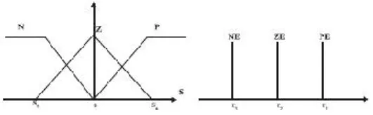
Here the sliding surface S be the input linguistic variable and fuzzy hitting control law 𝑈𝑓 be the output linguistic variable. The proposed controller uses the following variables.
The rule base involved in the fuzzy sliding mode system is given as follows
Rule 1: if S is p, then 𝑈𝑓 is PE Rule 2: if S is z, then 𝑈𝑓 is ZE Rule 3: if S is N, then 𝑈𝑓 is NE
Fig.3. membership function of input fuzzy sets for S
Then a fuzzy hitting control long can be estimate by fuzzy logic inference mechanism as follows
Where 0≤ 1≤ 1 ,0≤ 2≤1, and 0≤ 3≤1 are the firing strengths of rules 1,2,3; respectively ( 1 =r),( 1 = 0),( 3 = 0)are the centre of total membership functions PE,ZE and NE respectively ,r is a fuzzy parameter the .the relation ω1+ ω2 + ω3 = 1 is valid according to the special case of triangular membership functions.
IV. SIMULATION RESULTS AND
DISCUSSION
The induction motor drive system in indirect vector control mode is simulated in MATLAB environment using power system block set each with sliding mode controller (SMC) and fuzzy sliding mode control (FSMC).The controller’s performance are tested and compared for speed tracking. The tracking response of speed depicted in fig.4.Here it is observed that in case of SMC ,the actual speed is not exactly track the reference command speed, it has some error where as in case of FSMC it has been exactly track the reference command speed. The tracking response of torque depicted in figure. it is observed that in case of SMC ,the actual torque tracks the reference torque, but chattering phenomenon is present. Chattering is occurring due to large control gain in the hitting control law. However in case of FSMC, chattering is absent and actual torque smoothly tracks the reference torque. The alpha-beta stator current for SMC and FSMC is depicted in fig.6.From fig.6,it has been observed that alpha-beta axis current is completely decoupled in both the case., but in case of SMC chattering is present.
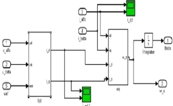
A. MAT LAB MODEL OF INDIRECT VECTOR CONTROL
OF IM DRIVE.
1. MATLAB DIAGRAM
Fig. 4: Mat lab Simulink diagram of indirect vector Control using Fuzzy Sliding Mode Controller
Fig.4.1
: Mat lab Simulink diagram of conversion abc –dq transformationFig. 4.2: Mat lab Simulink diagram Figure sliding mode Controller
SIMULATION RESULTS
Fig. 4.3: Speed response for periodic command with fuzzy sliding mode controller
Fig. 4.1: Torque response for periodic command with fuzzy sliding mode controller
IV. CONCLUSION
This paper has successfully demonstrated the application of the proposed fuzzy sliding mode control system to an indirect field-oriented induction motor drive for tracking periodic commands. The design and description of the classical sliding mode controller (SMC) is presented in detail. Then, the fuzzy logic control is used to mimic the hitting control law to remove the chattering. However, the developed fuzzy logic control with indirect vector control of induction motor drive shows fast response, smooth performance, and high dynamic response with speed changing and transient conditions
APPENDIX Specification of Induction Motor: Machine type-3 phase induction motor Rotor type-squirrel cage
Reference type-Stationary
5HP, 1445 rpm, 415V, 50 Hz, 4 poles Rs=7.34Ω,Rr=5.64Ω,
Ls=0.521H,Lr=0.521H,Lm=0.5H
J=0.16Kg.m2,B=0.035kg.m/s
ACKNOWLEDGEMENTS
I would like to thank Mr.T.Ravikumar, associate professor in EEE dept, and Mr. P.Ranjith Krishna, assistant professor in EEE dept, who had been guiding throughout the project and supporting me in giving technical ideas about paper and motivating me to complete then work efficiently and successfully.
REFERENCES
[1] B.K Bose “Modern power electronics and ac drives “Prentice-Hall Of India, New Delhi, 2008.
[2] Dr. Ch. Chengaiah and I Siva Prasad, “performance of induction motor drive by indirect vector controlled method using pi and fuzzy controllers” International Journal of Science, Environment and Technology, Vol. 2, No 3, 2013, 457 – 469.
[3] Biranchi Narayan Kar, K.B. Mohanty, Madhu Singh, Satish choudhury,“Indirect Vector Control of Induction Motor Using Fuzzy Sliding Mode Controller”Proc Department of Electrical Engineering, National Institute of Technology, Rourkela-769008
[4] Bharat Bhushan, Madhusudan Singh, PremPrakash, “Performance Analysis of Field Oriented Induction Motor using Fuzzy PI and Fuzzy Logic based Model Reference Adaptive Control,” International Journal of Computer Applications (0975 – 8887) Volume 17– No.4, March 2011,”
[5] D. Archana, Kotyada. Kalyani, B. Shankar Prasad, “Efficiency Optimization Control of Induction Motor Using Fuzzy Logic” International Journal of Soft Computing and Engineering (IJSCE) ISSN: 2231-2307, Volume-2, Issue-3, July 2012. [6] M Nasir Udin,Tawfik S.Radwan,and M.Azizur Rahman,“
Performance of Fuzzy-Logic-Based Indirect vector control for induction motor drive,”IEEE Transaction on Industry Applications, vol.38,no.5,September/October 2002
.
[7] Gilberto C.D.Sousa,Bimal K.Bose and John G.Cleland
“Fuzzy Logic Based On-Line Efficiency Optimisation Vector-Controlled Induction Motor Drives,”IEEE Trans.Industrial Electronics, Vol.42,pp.192-198,April 1995.
1* M.V.Anusha is pursuing M.Tech in Geethanjali Institute of Science and Technology, Nellore, JNTU ANANTAPUR. Her Specialization is Power Electronics. Her research interest includes Power Electronics and Applications. Attended for seminars, quiz, MATLAB workshop. Email id- [email protected] 2*. P.Ranjith Krishna received Bachelor of Technology degree in Electrical & Electronic Engineering from MRRITS Engineering College, University of JNTU and Master’s Degree from NBKR College of Engineering, University of JNTU. Currently working as an Associate Professor of EEE branch in GIST, Nellore, and AP. He is having a total experience of 3 years in GIST College. His areas of interest include Power system stability, fuzzy logic systems. Email [email protected]
3*.T.RaviKumar received Bachelor of Technology degree in Electrical & Electronic Engineering from Narayana Engineering College, Nellore. JNTU and Master’s Degree from JNTU College of engineering, Ananthapur. Currently, pursuing PhD in KL University and working as an associate professor in Geethanjali institute of science and technology, Nellore, JNTU Ananthapur, A.P. he is having 7years 6 months of teaching experience. His areas in power systems and power electronics & drives. His research interests include electric machines, machine drives, power electronics/conversion, and practical use and improvement of modern control and power electronics control.